JAGUAR X308 1998 2.G Workshop Manual
Manufacturer: JAGUAR, Model Year: 1998, Model line: X308, Model: JAGUAR X308 1998 2.GPages: 2490, PDF Size: 69.81 MB
Page 1031 of 2490
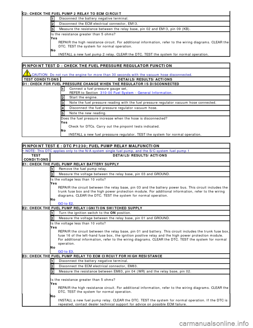
C2: CHECK THE FUEL
PUMP 2 RELAY TO ECM CIRCUIT
Di
sconnect the battery negative terminal.
1
D
isconnect the ECM electrical connector, EM13.
2
Meas
ure the resistance between the rela
y base, pin 02 and EM13, pin 09 (KB).
3
Is th
e resistance greater than 5 ohms?
Yes REPAIR the high resistance circuit. For additional information, refer to the wiring diagrams. CLEAR the
DTC. TEST the system for normal operation.
No INSTALL a new fuel pump 2 relay. CLEAR the DT C. TEST the system for normal operation.
P
INPOINT TEST D : CHECK THE FUEL PRESSURE REGULATOR FUNCTION
CAUTI
ON: Do not run the engine for more than
30 seconds with the vacuum hose disconnected.
T
EST CONDITIONS
D
ETAILS/RESULTS/ACTIONS
D
1: CHECK FOR FUEL PRESSURE CHANGE
WHEN THE REGULATOR IS DISCONNECTED
Connect a
fuel pressure gauge set,
REFER to Section 310
-00
Fuel System
-
General Informati
on
. 1
St
art the engine.
2
N
ote the fuel pressure readin
g with the fuel pressure regu lator vacuum hose connected.
3
Di
sconnect the fuel pressu
re regulator vacuum hose.
4
N
ote the new reading.
5
Doe
s the fuel pressure increase when the hose is disconnected?
Yes Check for DTCs. Carry out the pinpoint tests indicated.
No INSTALL a new fuel presssure regulator. TEST the system for normal operation.
P
INPOINT TEST E : DTC P1230;
FUEL PUMP RELAY MALFUNCTION
•
NOTE: This DTC applies only to the N/A system si
ngle fuel pump, and the S/C system fuel pump 1
TE
ST
CONDITIONS
D
ETAILS/RESULTS/ACTIONS
E1
: CHECK THE FUEL PUMP
RELAY BATTERY SUPPLY
R
emove the fuel pump relay.
1
Meas
ure the voltage between the
relay base, pin 03 and GROUND.
2
Is th
e voltage less than 10 volts?
Yes REPAIR the circuit between the rela y base, pin 03 and the battery power bus. This circuit includes the
trunk fuse box and the high power protection module . For additional information, refer to the wiring
diagrams. CLEAR the DTC. TEST th e system for normal operation.
No GO to E2
.
E2
: CHECK THE FUEL PUMP RELAY IGNITION SWITCHED SUPPLY
Turn the ignition swi
tch to the
ON position.
1
Meas
ure the voltage between the
relay base, pin 01 and GROUND.
2
Is th
e voltage less than 10 volts?
Yes REPAIR the circuit between the rela y base, pin 01 and battery. This circuit includes the trunk fuse box,
fuse 16 of the left-hand fuse box, the ignition po
sitive relay and the high power protection module.
For additional information, refer to the wiring diagrams. CLEAR the DTC. TEST the system for normal
operation.
No GO to E3
.
E3
: CHECK THE FUEL PUMP RELAY TO
ECM CIRCUIT FOR HIGH RESISTANCE
Di
sconnect the battery negative terminal.
1
D
isconnect the ECM electrical connector, EM83.
2
Meas
ure the resistance between EM83, pi
n 04 (WR) and the relay base, pin 02.
3
Is th
e resistance greater than 5 ohms?
Yes REPAIR the high resistance circuit. For additional information, refer to the wiring diagrams. CLEAR the
DTC. TEST the system for normal operation.
No
INSTALL a new fuel pump relay. CLEAR the DTC. TEST the system for normal operation. If the DTC is
repeated, contact dealer technical support for advice on possible ECM failure.
Page 1032 of 2490
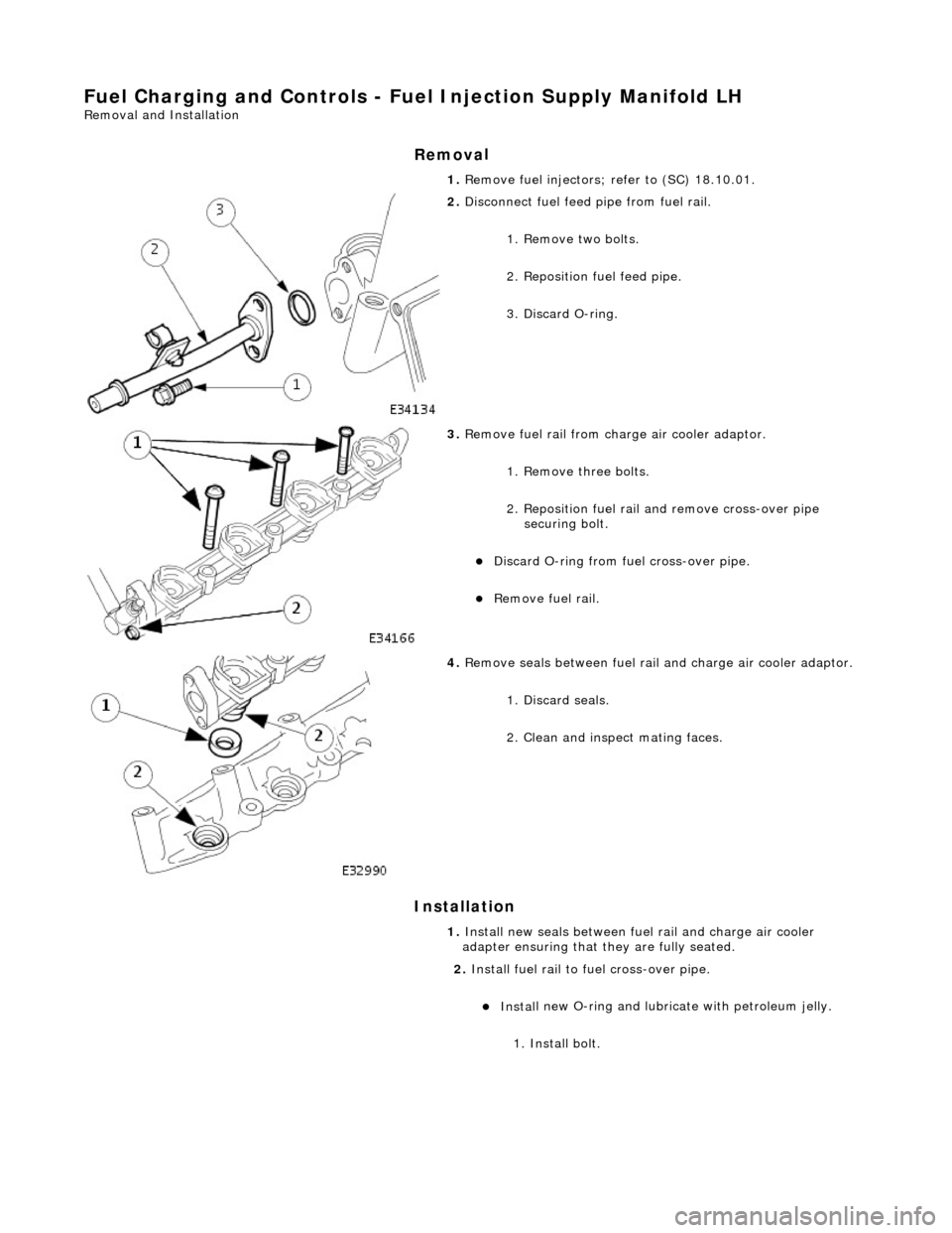
Fuel Char
ging and Controls - Fu
el Injection Supply Manifold LH
Remo
val and Installation
Remov
a
l
Installation
1. Re
move fuel injectors; refer to (SC) 18.10.01.
2. Disc
onnect fuel feed
pipe from fuel rail.
1. Remove two bolts.
2. Reposition fuel feed pipe.
3. Discard O-ring.
3. Re
move fuel rail from charge air cooler adaptor.
1. Remove three bolts.
2. Reposition fuel rail and remove cross-over pipe securing bolt.
Di
scard O-ring from fuel cross-over pipe.
R
e
move fuel rail.
4. Re
move seals between fuel rail
and charge air cooler adaptor.
1. Discard seals.
2. Clean and inspect mating faces.
1. Install new seals between fuel rail and charge air cooler
adapter ensuring that they are fully seated.
2. Install fuel rail to fuel cross-over pipe.
Inst al
l new O-ring and lubricate with petroleum jelly.
1. Install bolt.
Page 1033 of 2490

3.
Install
fuel rail to charge air cooler adaptor.
Locate fuel
rail into adaptor.
1. Install bolts.
4. Conne
ct fuel feed pi
pe to fuel rail.
1. Install new O-ring and lubricate with petroleum jelly.
2. Install two bolts.
5. Install fuel injectors; refer to (SC) 18.10.01.
Page 1034 of 2490
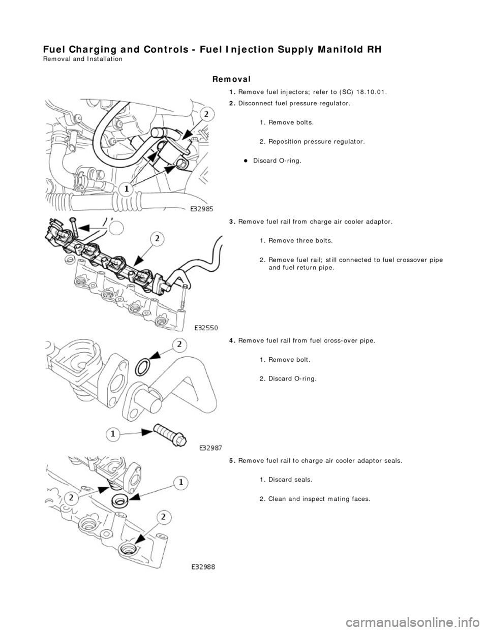
Fuel Char
ging and Controls - Fu
el Injection Supply Manifold RH
Remo
val and Installation
Remov
a
l
1.
Re
move fuel injectors; refer to (SC) 18.10.01.
2. Disc
onnect fuel pressure regulator.
1. Remove bolts.
2. Reposition pres sure regulator.
Disc
ard O-ring.
3. Re
move fuel rail from charge air cooler adaptor.
1. Remove three bolts.
2. Remove fuel rail; still co nnected to fuel crossover pipe
and fuel return pipe.
4. Re
move fuel rail from fuel cross-over pipe.
1. Remove bolt.
2. Discard O-ring.
5. Re
move fuel rail to charge air cooler adaptor seals.
1. Discard seals.
2. Clean and inspect mating faces.
Page 1035 of 2490

I
nstallation
1.
Inst
all new seals between fuel rail and charge air cooler
adapter, ensuring they are fully seated.
2. Install
fuel rail to fuel cross-over pipe.
1. Install new O-ring and lubricate with petroleum jelly.
2. Install bolt.
3. Install
fuel rail to charge air cooler adaptor.
1. Align fuel rail to adaptor; still connected to fuel crossover pipe and fuel return pipe. Locate fuel rail
into adaptor.
2. Install three bolts which se cure fuel rail to adaptor.
Tighten to 18-24 Nm.
4. Install
fuel pressure regulator.
Install a new O-r
ing to fu
el pressure regulator and
lubricate with petroleum jelly
1. Install bolts.
5. Install fuel injectors; refer to (SC) 18.10.01.
Page 1036 of 2490
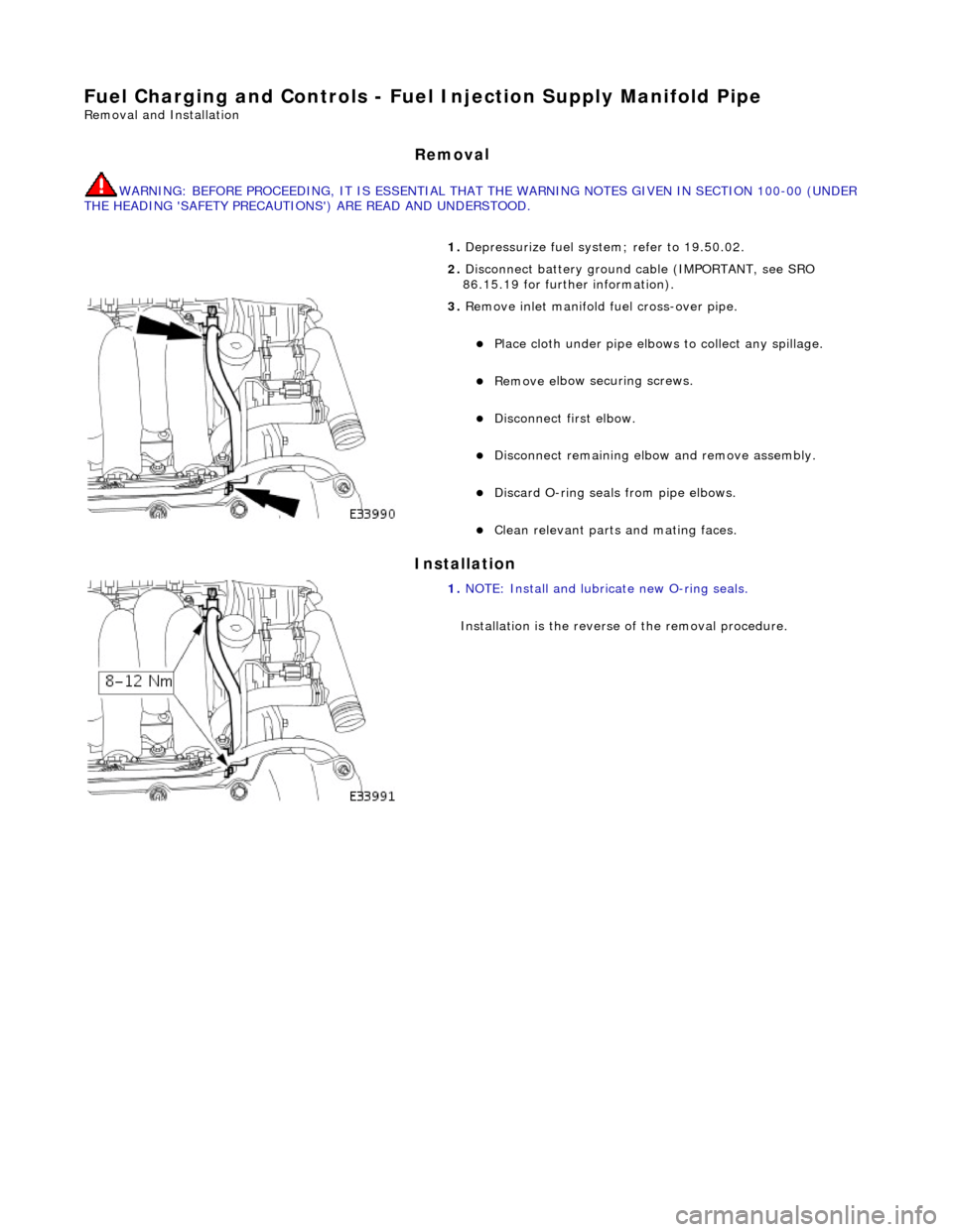
Fuel Char
ging and Controls - Fuel
Injection Supply Manifold Pipe
Remo
val and Installation
Remov
a
l
WARNING: B
E
FORE PROCEEDING, IT IS ESSENTIAL THAT
THE WARNING NOTES GIVEN IN SECTION 100-00 (UNDER
THE HEADING 'SAFETY PRECAUTION S') ARE READ AND UNDERSTOOD.
In
stallation
1.
De
pressurize fuel syst
em; refer to 19.50.02.
2. Disconnect battery ground cable (IMPORTANT, see SRO
86.15.19 for further information).
3. Re
move inlet manifold
fuel cross-over pipe.
Plac
e cloth under pipe elbows
to collect any spillage.
Remove e
lbow securing screws.
Di
sc
onnect first elbow.
Disc
onnect remaining elbow and remove assembly.
Discard O
-
ring seals
from pipe elbows.
Clean relevant parts and mating faces.
1. NOTE : Install
and lubricate new O-ring seals.
Installation is th e reverse of the removal procedure.
Page 1037 of 2490
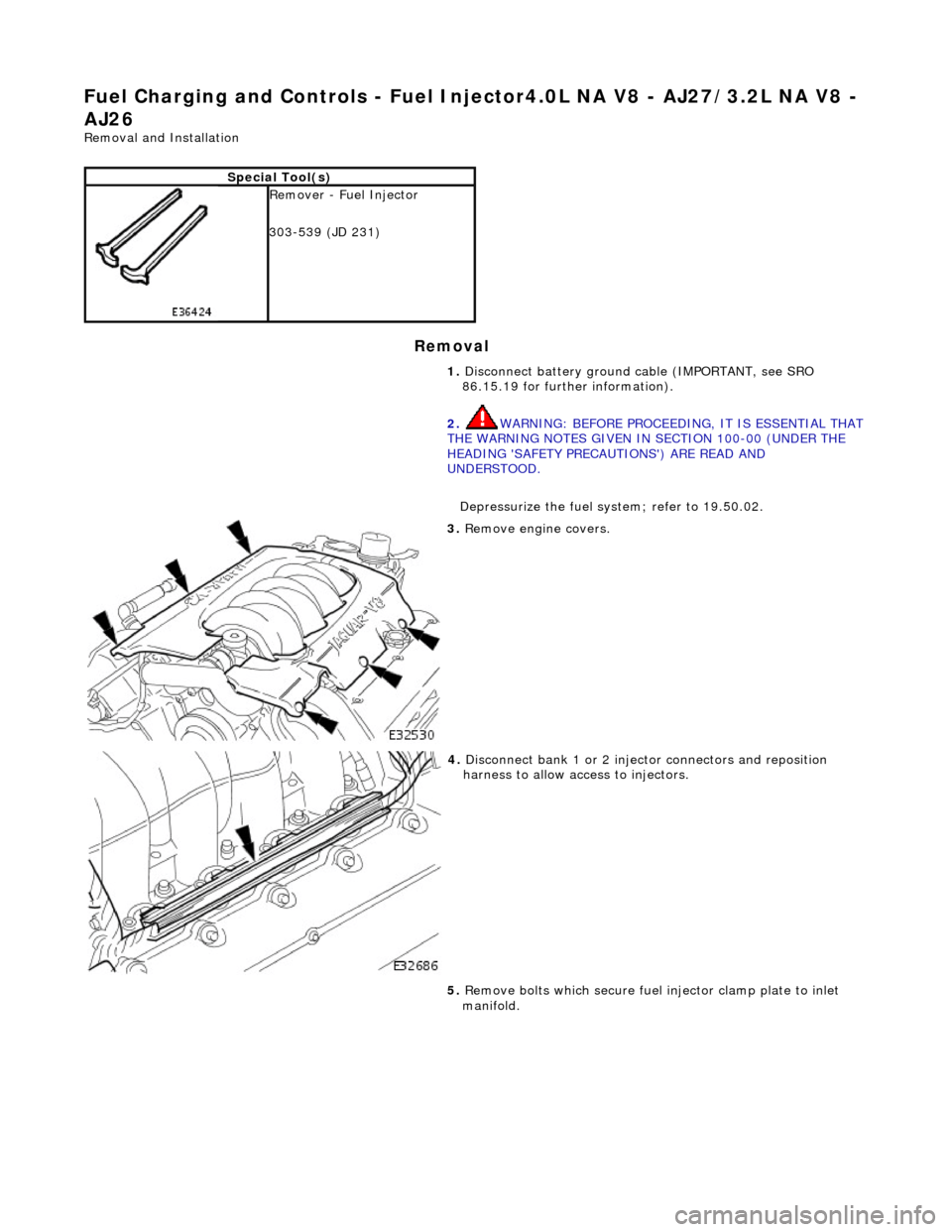
Fuel Ch
arging and Controls
- Fuel Injector4.0L NA V8 - AJ27/3.2L NA V8 -
AJ26
Re
moval and Installation
Remov
al
S
pecial Tool(s)
R
emover - Fuel Injector
303-539 (JD 231)
1. Disconnect battery ground cable (IMPORTANT, see SRO
86.15.19 for further information).
2. WARNING: BEFORE PROCEEDING, IT IS ESSENTIAL THAT
THE WARNING NOTES GIVEN IN SECTION 100-00 (UNDER THE
HEADING 'SAFETY PRECAUTIONS') ARE READ AND
UNDERSTOOD.
Depressurize the fuel sy stem; refer to 19.50.02.
3. R
emove engine covers.
4. Di
sconnect bank 1 or 2 inject
or connectors and reposition
harness to allow access to injectors.
5. Remove bolts which secure fuel injector clamp plate to inlet
manifold.
Page 1038 of 2490

In
stallation
6.
Us
ing special tool JD-231, remove injector(s).
Discard
seals an
d clean all mating faces.
1. Installation
is a reversal
of the removal procedure.
Instal
l new seals and lubricate with petroleum jelly.
Page 1039 of 2490
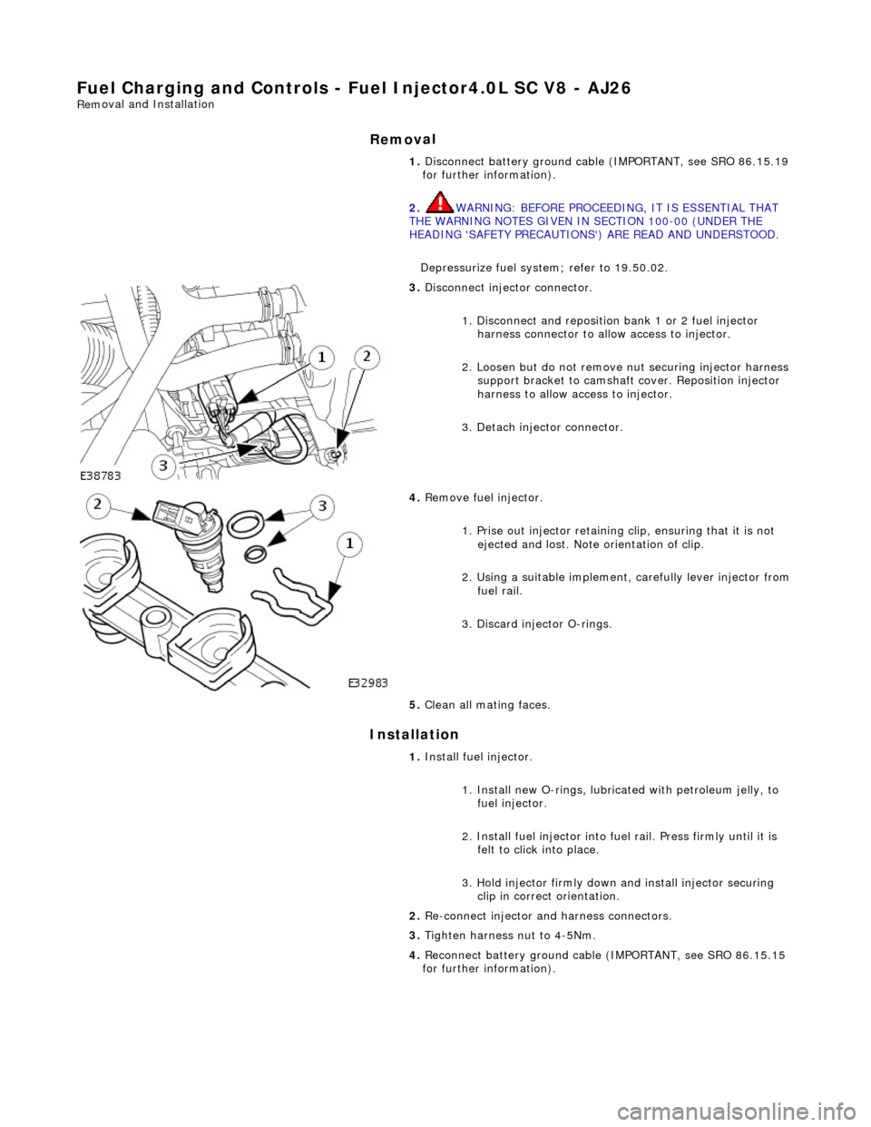
Fuel Charging and Controls
- Fuel Injector4.0L SC V8 - AJ26
Rem
oval and Installation
Remov
al
Installation
1.
Disconnect battery ground cabl e (IMPORTANT, see SRO 86.15.19
for further information).
2. WARNING: BEFORE PROCEEDING, IT IS ESSENTIAL THAT
THE WARNING NOTES GIVEN IN SECTION 100-00 (UNDER THE
HEADING 'SAFETY PRECAUTIONS') ARE READ AND UNDERSTOOD.
Depressurize fuel system; refer to 19.50.02.
3.
Disconnect injector connector.
1. Disconnect and reposition bank 1 or 2 fuel injector harness connector to allow access to injector.
2. Loosen but do not remove nut securing injector harness support bracket to camshaft cover. Reposition injector
harness to allow access to injector.
3. Detach injector connector.
4.
Remove fuel injector.
1. Prise out injector retaining clip, ensuring that it is not ejected and lost. Note orientation of clip.
2. Using a suitable implement, carefully lever injector from
fuel rail.
3. Discard injector O-rings.
5. Clean all mating faces.
1. Install fuel injector.
1. Install new O-rings, lubricat ed with petroleum jelly, to
fuel injector.
2. Install fuel injector into fuel rail. Press firmly until it is felt to click into place.
3. Hold injector firmly down and install injector securing clip in correct orientation.
2. Re-connect injector and harness connectors.
3. Tighten harness nut to 4-5Nm.
4. Reconnect battery ground cable (IMPORTANT, see SRO 86.15.15
for further information).
Page 1040 of 2490
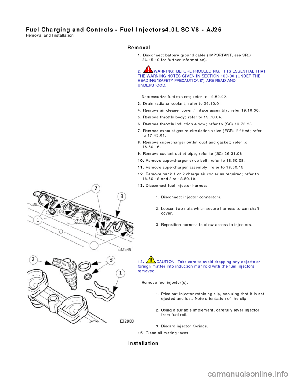
Fuel Char
ging and Controls - Fu
el Injectors4.0L SC V8 - AJ26
Remo
val and Installation
Remov
a
l
Installation
1. Disc onne
ct battery ground cable (IMPORTANT, see SRO
86.15.19 for further information).
2. WARNING: BEFORE PROCEEDING, IT IS ESSENTIAL THAT
THE WARNING NOTES GIVEN IN SECTION 100-00 (UNDER THE
HEADING 'SAFETY PRECAUTIONS') ARE READ AND
UNDERSTOOD.
Depressurize fuel syst em; refer to 19.50.02.
3. Drain radiator coolant; refer to 2
6.10.01.
4. Remove air cleaner cover / inta ke assembly; refer 19.10.30.
5. Remove throttle body; refer to 19.70.04.
6. Remove throttle induction elbo w; refer to (SC) 19.70.28.
7. Remove exhaust gas re-circulation valve (EGR) if fitted; refer
to 17.45.01.
8. Remove supercharger outlet duct and gasket; refer to
18.50.16.
9. Remove coolant outlet pipe; refer to (SC) 26.31.08 .
10. Remove supercharger drive belt; refer to 18.50.08.
11. Remove supercharger assembly; refer to 18.50.15.
12. Remove bank 1 or 2 charge air cooler as required; refer to
18.50.18 and / or 18.50.19.
13 . Di
sconnect fuel injector harness.
1. Disconnect injector connectors.
2. Loosen two nuts which se cure harness to camshaft
cover.
3. Reposition harness to al low access to injectors.
14. CAUTI
ON: Take care to avoi
d dropping any objects or
foreign matter into induction ma nifold with the fuel injectors
removed.
Remove fuel injector(s). 1. Prise out injector retaining clip, ensuring that it is not
ejected and lost. Note orientation of the clip.
2. Using a suitable implemen t, carefully lever injector
from fuel rail.
3. Discard injector O-rings.
15 . Cle
an all mating faces.