vi number JAGUAR X308 1998 2.G Workshop Manual
[x] Cancel search | Manufacturer: JAGUAR, Model Year: 1998, Model line: X308, Model: JAGUAR X308 1998 2.GPages: 2490, PDF Size: 69.81 MB
Page 1016 of 2490
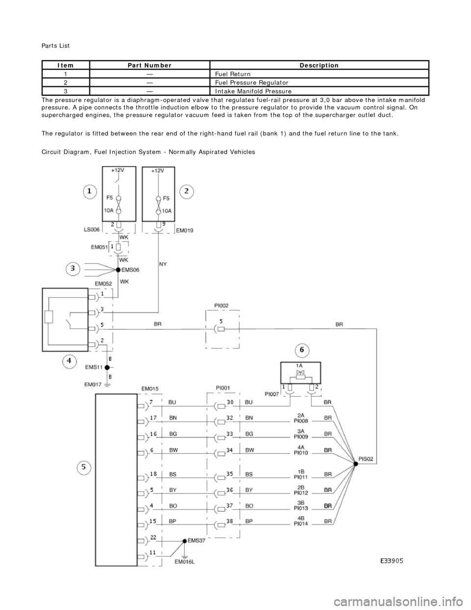
Pa
rts List
The pressure regulator is a diap hragm-operated valve that regula tes fuel-rail pressure at 3,0 bar above the intake manifold
pressure. A pipe connects the throttle induction elbow to the pressure regulator to provide the vacuum control signal. On
supercharged engines, the pressure regulator vacuum feed is taken from the top of the supercharger outlet duct.
The regulator is fitted between the rear end of the right-hand fuel rail (bank 1) and the fuel return line to the tank.
Circuit Diagram, Fuel Injection Syst em - Normally Aspirated Vehicles
Ite
m
Par
t
Number
De
scr
iption
1—F
u
el Return
2—F
u
el Pressure Regulator
3—Inta
k
e Manifold Pressure
Page 1017 of 2490
Ci
rcuit references to injectors:
'A' refers to bank 1;
'B' refers to bank 2.
Fuel C
harging and Controls - Supercharged Vehicles
Ci
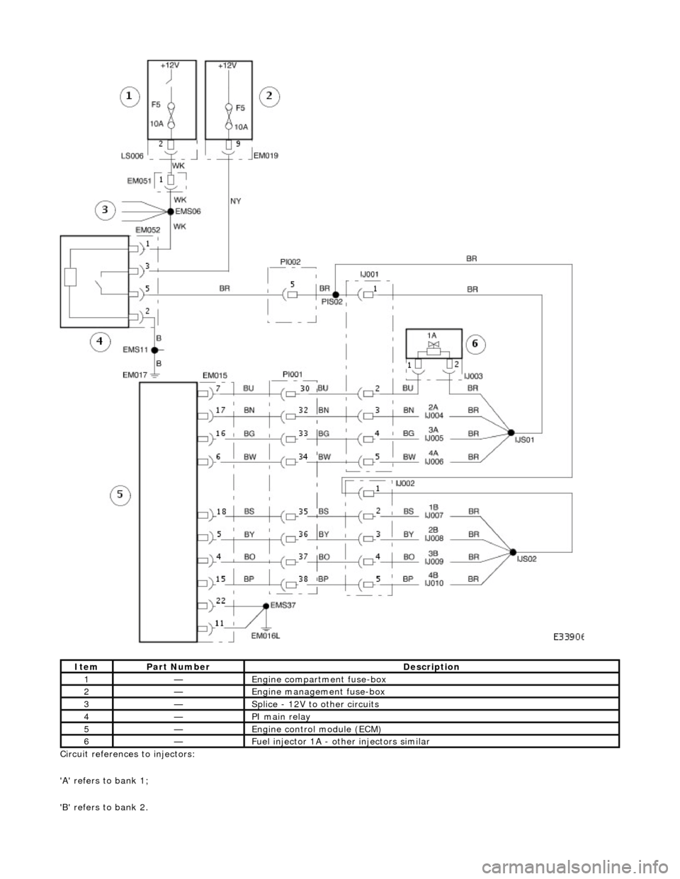
rcuit Diagram, Fuel Injection
System - Supercharged Vehicles
It
em
Par
t Number
De
scription
1—E
ngine compartment fuse-box
2—Engine
management fuse-box
3—Splice
- 12V to
other circuits
4—PI m
ain relay
5—Engine
control module (ECM)
6—Fue
l injector 1A - other injectors similar
Page 1018 of 2490
Ci rcui
t references to injectors:
'A' refers to bank 1;
'B' refers to bank 2.
It e
m
Par
t
Number
De
scr
iption
1—E
n
gine compartment fuse-box
2—Engine
m
anagement fuse-box
3—Splice
- 12V to ot
her circuits
4—PI m
a
in relay
5—Engine
control module (E
CM)
6—Fue
l
injector 1A - other injectors similar
Page 1021 of 2490
CAUTI
ON: When probing connectors to take
measurements in the course of the pinpoint tests, use the adaptor kit,
part number 3548-1358-00.
• NOTE: When performing electrical voltag e or resistance tests, always use a digital multimeter (DMM) accurate to 3
decimal places, and with an up-t o-date calibration certificate. When testing resistance, always take the resistance of the
DMM leads into account.
• NOTE: Check and rectify basic faults before beginning diagnostic ro utines involving pinpoint tests.
Sy
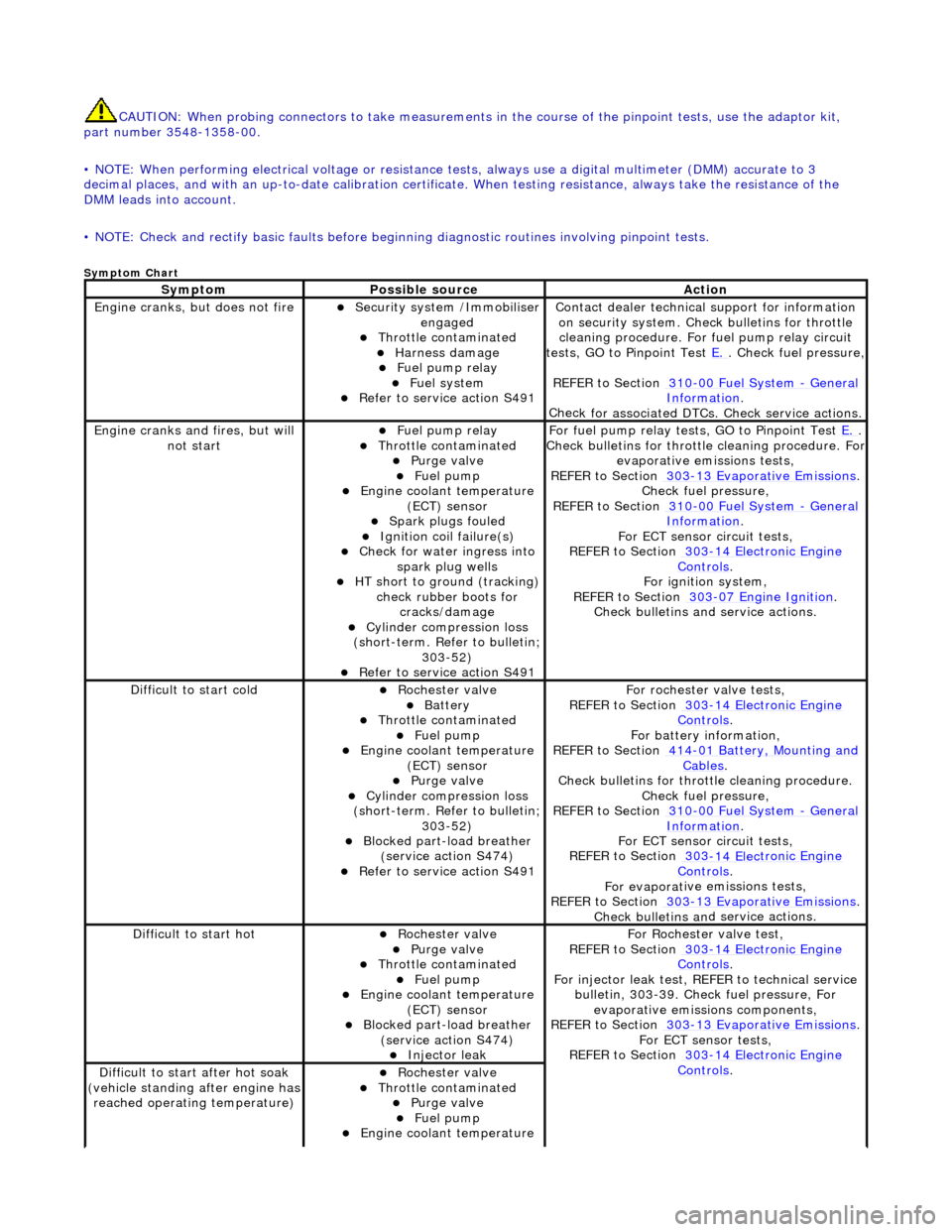
mptom Chart
Sy
mptom
Possib
le source
Acti
on
Engine
cranks, but does not fire
Secu
rity system /Immobiliser
engaged
Thr
ottle contaminated
Harness damage
F
uel pump relay
Fue
l system
R
efer to service action S491
Contact dealer techn
ical
support for information
on security system. Chec k bulletins for throttle
cleaning procedure. For fuel pump relay circuit
tests, GO to Pinpoint Test E.
.
Check fuel pressure,
REFER to Section 310
-00
Fuel System
- Gen
eral
Informati
on
.
Chec
k for associated DTCs
. Check service actions.
Engine
cranks and fires, but will
not start
F
uel pump relay
Thr
ottle contaminated
Purge
valve
Fue
l pump
Engine coolan
t temperature
(ECT) sensor
Spark plugs
fouled
Ignition coil
failure(s)
Check f
or water ingress into
spark plug wells
HT sho
rt to ground (tracking)
check rubber boots for cracks/damage
Cyl
inder compression loss
(short-term. Refer to bulletin;
303-52)
R
efer to service action S491
F
or fuel pump relay tests,
GO to Pinpoint Test E.
.
Check bull
etins for throttle cleaning procedure. For
evaporative emissions tests,
REFER to Section 303
-1
3 Evaporative Emissions
. Chec
k fuel pressure,
REFER to Section 310
-00
Fuel System
- Ge
neral
Informati
on
.
F
or ECT sensor circuit tests,
REFER to Section 303
-14 Elec
tronic Engine
Controls.
For ign
ition system,
REFER to Section 303
-07
Engine Ignition
.
Check bulletins an d service
actions.
D
ifficult to start cold
Roc
hester valve
Batt
ery
Thr
ottle contaminated
Fue
l pump
Engine coolan
t temperature
(ECT) sensor
Purge
valve
Cyl
inder compression loss
(short-term. Refer to bulletin;
303-52)
Blocked part-load breather (
service action S474)
R
efer to service action S491
F
or rochester valve tests,
REFER to Section 303
-14 Elec
tronic Engine
Controls.
F
or battery information,
REFER to Section 414
-0
1 Battery, Mounting and
Cables.
Check bull
etins for throttle cleaning procedure.
Check fuel pressure,
REFER to Section 310
-00
Fuel System
- Ge
neral
Informati
on
.
F
or ECT sensor circuit tests,
REFER to Section 303
-14 Elec
tronic Engine
Controls.
For evaporat
ive emissions tests,
REFER to Section 303
-1
3 Evaporative Emissions
. Check bulletins an
d
service actions.
D
ifficult to start hot
Roc
hester valve
Purge
valve
Thr
ottle contaminated
Fue
l pump
Engine coolan
t temperature
(ECT) sensor
Blocked part-load breather (
service action S474)
Injec
tor leak
F
or Rochester
valve test,
REFER to Section 303
-14 Elec
tronic Engine
Controls.
Fo
r injector leak test, REFER to technical service
bulletin, 303-39. Check fuel pressure, For evaporative emissions components,
REFER to Section 303
-1
3 Evaporative Emissions
. F
or ECT sensor tests,
REFER to Section 303
-14 Elec
tronic Engine
Controls. D
ifficult to start after hot soak
(vehicle standing after engine has
reached operating temperature)
Roc
hester valve
Thr
ottle contaminated
Purge
valve
Fue
l pump
Engine coolan
t temperature
Page 1042 of 2490
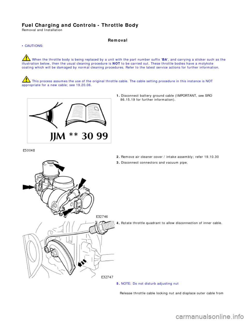
Fuel Char
ging and Controls - Throttle Body
Re
mo
val and Installation
Remov
a
l
• C
A
UTIONS:
When the throttle body is being replaced by a unit with the part number suffix ' BA', and carrying a sticker such as the
illustration below, then the usual cleaning procedure is NOT to be carried out. These thro ttle bodies have a molykote
coating which will be damaged by normal cleaning procedures. Refer to the latest service action s for further information.
This process assumes the use of the original throttle ca ble. The cable setting procedure in this instance is NOT
appropriate for a new cable; see 19.20.06.
1. Disc onne
ct battery ground cable (IMPORTANT, see SRO
86.15.19 for further information).
2. Remove air cleaner cover / in take assembly; refer 19.10.30
3. Disc
onnect connectors and vacuum pipe.
4. Ro
tate throttle quadrant to allow disconnection of inner cable.
5. NOTE: Do not disturb adjusting nut
Release throttle cable locking nut and displace outer cable from
Page 1049 of 2490

Accessory Drive - Accessory Drive
Description an
d Operation
Parts List
Cran
kshaft Pulley
The combined crankshaft
pulley and torsio
nal vibration damper drives a single, seve n ribbed vee belt. The belt drives all of
the engine-mounted accessories; the generator, the power assi sted steering pump, the air-conditioning compressor and the
coolant water pump.
I
dler Pulley
An i
dler pulley, on the right-hand
accessory mounting, increases the wrap-angle around the generator pulley.
Coolant Pump Drive
The coolan
t pump pulley is the
uppermost of the accessory drive pulleys. Th e coolant pump is fitted between the two
cylinder banks on the front face of the engine.
Air Conditioning Compressor Drive
Thi
s is positioned at the lowest poin
t of the front-end accessory-d rive on the left hand side accessory mounting.
It
em
Par
t Number
De
scription
1—Coo
lant Pump Drive
2—Ai
r-Conditioning Compressor Drive
3—Power Steer
ing Pump Drive
4—Au
tomatic Belt Tensioner
5—Crankshaft Pul
ley
6—Idle
r Pulley
7—Generator Dri
ve
Page 1052 of 2490

P a
rts List
All engine accessories are rigidly-mounted onto the cylinder block by means of accessory moun ting brackets on the left and
right-hand sides of the engine.
The left-hand bracket supports the air-cond itioning compressor and steering pump.
The right-hand bracket su pports the generator.
Dowels between the accessory mounting br ackets and the engine ensure that the accessory pulleys are accurately aligned
with the accessory drive belt.
A ccess
ory Drive on Supercharged Engines
The front
en
d accessory drive description and information for the
supercharged engine is identical to that given above. The
only difference is that the drive belt for the supercharger passes im mediately in front of the accessory drive belt. Therefore,
before any work can be done on the acce ssory drive belt and associated components, the supercharg er drive belt must first
be removed.
It e
m
Par
t
Number
De
scr
iption
1—R
i
ght Hand Mounting Bracket
2—Left H
and Mounting Bracket
Access
ory Mounting Brackets
Page 1066 of 2490
Starting System - Starting System
Diagn
osis and Testing
I
n
spection and Verification
W
A
RNING: Make sure
the vehicle is in NEUTRAL or PARK for vehicles with au tomatic transmission, NEUTRAL for
vehicles with manual transmissi on, and apply the parking brake. Failure to foll ow this instruction may result in personal
injury.
1. 1. Verify the customer concern.
2. 2. Visually inspect for obvious signs of mechanical or electrical damage, correct fitment, etc.
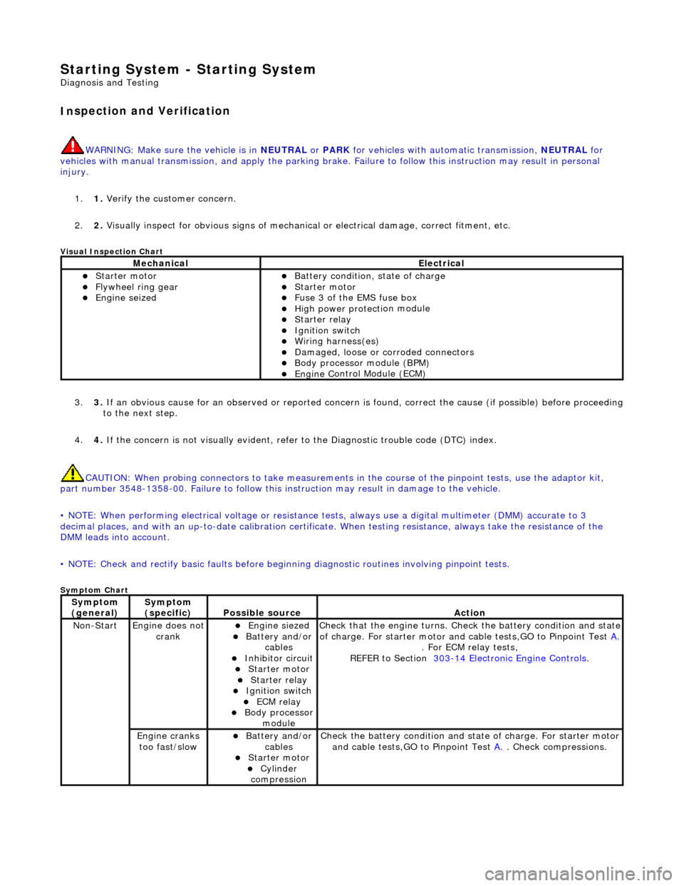
Vi
sual Inspection Chart
3.
3. If an obvi
ous cause for an observed or
reported concern is found, correct th e cause (if possible) before proceeding
to the next step.
4. 4. If the concern is not visually evident, refer to the Diagnostic trouble code (DTC) index.
CAUTION: When probing connectors to take measurements in the course of the pinpoint tests, use the adaptor kit,
part number 3548-1358-00. Failure to follow this in struction may result in damage to the vehicle.
• NOTE: When performing electrical voltag e or resistance tests, always use a digital multimeter (DMM) accurate to 3
decimal places, and with an up-t o-date calibration certificate. When testing resistance, always take the resistance of the
DMM leads into account.
• NOTE: Check and rectify basic faults before beginning diagnostic ro utines involving pinpoint tests.
Sym
ptom Chart
MechanicalElectrical
Starte
r motor
Flywheel
ring gear
Engine
s
eized
Batter
y condition, state of charge
Starte
r motor
F
u
se 3 of the EMS fuse box
High
power protec ti
on module
Starter relay Ignition switc
h
W
i
ring harness(es)
Damaged, loose or corroded connector
s
Body processor module (B
PM)
Engine
C
ontrol Module (ECM)
Sy
m
ptom
(
gene r
al)
Sy
m
ptom
(specific)
Possib l
e source
Acti
o
n
No
n
-Start
Engine does
not
crankEngine s
iezed
Batt
ery and
/or
cables
Inhibitor circuit St arte
r motor
Starter relay Ignition switc
h
ECM relay Body processor
modu le
Check that
the engine turns. Check the battery condition and state
of charge. For starter motor and ca ble tests,GO to Pinpoint Test A.
. For ECM relay
tests,
REFER to Section 303
-14
Electronic Engine Controls
.
Engine
c
ranks
too fast/slow
Batt ery and
/or
cables
St arte
r motor
Cy
linder
com
pression
Check the battery con
dition
and st
ate of charge. For starter motor
and cable tests,GO to Pinpoint Test A.
. Chec
k compressions.
Page 1073 of 2490

Engine Igni
tion -
Engine Ignition
Description an
d Operation
I
gnition coil and spark plug reference
Any positional r
eferences are base
d upon the following convention:
viewing from the driving position, the right-hand cylinder bank is designated bank 1 (A on circuit diagrams) and the left-
hand cylinder bank as bank 2 (B on circuit diagrams).
The cylinder bores of each bank are number ed 1 to 4, from the front of the vehicle.
Ig
nition System
Th
e ignition system provides timing cont
rol in accordance with the engine mana gement strategy and powertrain sensor
inputs; the system consists of:
engine
control module
igni
tion coils supply relay
ignit
ion control modules
igni
tion coils
spark plu
gs
Engine Control Module (ECM)
pr
ovides triggering for the ignition control modules
to control individual firing of the spark plugs
supplies ground for
the igni
tion coils supply relay
I
gnition Coils Supply Relay
The
ignition coils supply relay is located
in the engine and transmission control mo dule compartment; refer to Relay Details
in Electrical Wiring and Circuit Protection, Section 418-01.
The ECM switches a ground to the coil of the ignition coils supply relay; the relay energizes and switches a 12v supply to the
ignition control modules and the ignition coils.
I
gnition Control Modules
Page 1074 of 2490

T w
o ignition control modules control firing of the spark plug
s when triggered by the engine control module (ECM); the
modules provide an interface between the ECM and the coil on plugs such that:
Ignition cont
rol module 1 drives bank 1 -
coils 1 and 4, bank 2 - coils 2 and 3.
Ignition cont
rol module 2 drives bank 1 -
coils 2 and 3, bank 2 - coils 1 and 4.
Ite
m
Par
t
Number
De
scr
iption
1—Ignition control
module 1
2—Ignition control module 2