vi number JAGUAR X308 1998 2.G Manual PDF
[x] Cancel search | Manufacturer: JAGUAR, Model Year: 1998, Model line: X308, Model: JAGUAR X308 1998 2.GPages: 2490, PDF Size: 69.81 MB
Page 422 of 2490
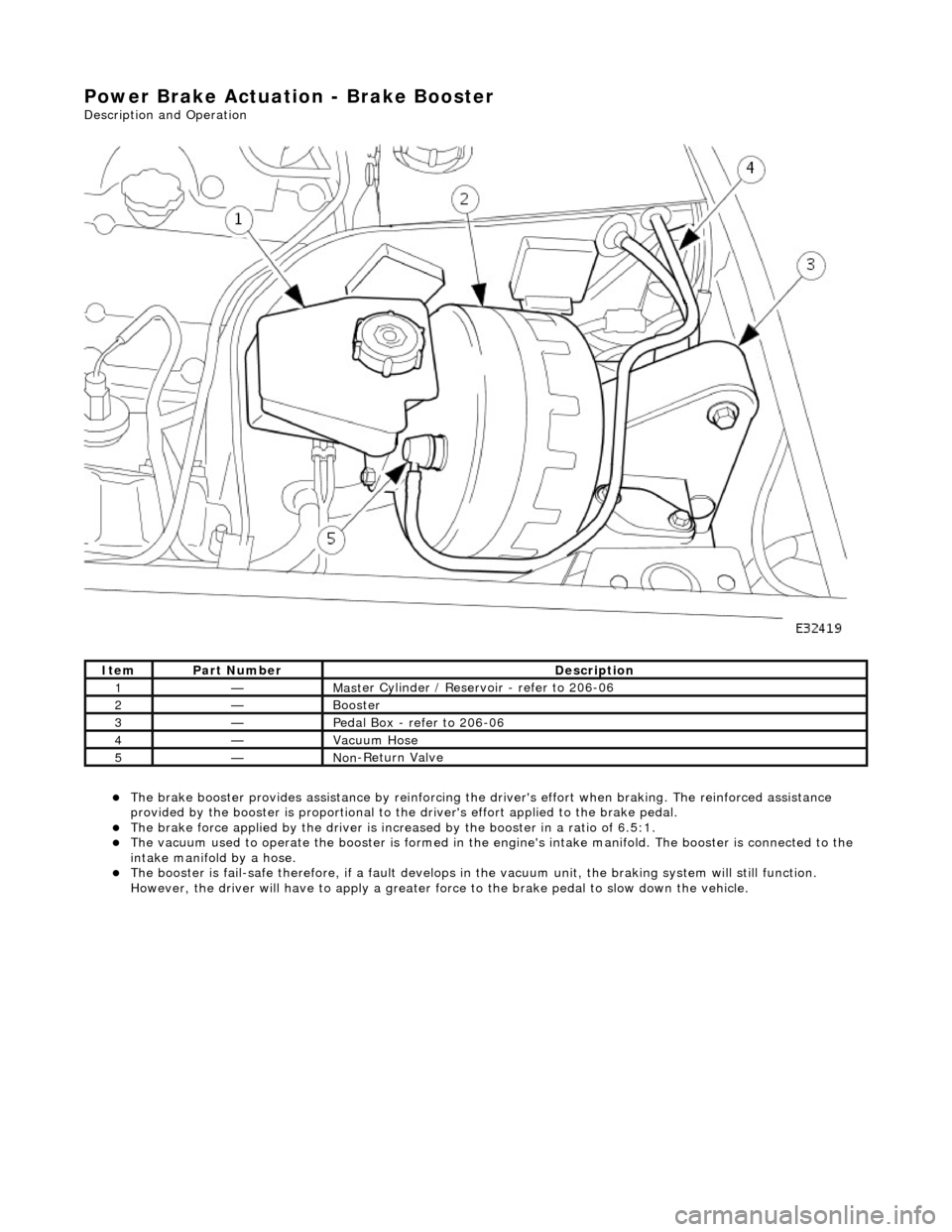
Power Brake Actuation - Brake Booster
Description and Operation
The brake b
ooster provides assi
stance by reinforcing the driver's effort when brakin g. The reinforced assistance
provided by the booster is proportional to the driver's effort applied to the brake pedal.
The brake force applied by
the driver is incr
eased by the booster in a ratio of 6.5:1.
Th
e vacuum used to operate the booster
is formed in the engine's intake manifold. The booster is connected to the
intake manifold by a hose.
The boost
er is fail-safe therefore, if a fault develops in
the vacuum unit, the braking system will still function.
However, the driver will have to apply a greater fo rce to the brake pedal to slow down the vehicle.
It e
m
Par
t
Number
De
scr
iption
1—Mas
t
er Cylinder / Reservoir - refer to 206-06
2—Booster
3—Pedal Box
- refer to 206-06
4—Vacuu
m
Hose
5—No
n
-Return Valve
Page 423 of 2490
Power Brake Actuatio
n - Brake Booster
Re
moval and Installation
Remov
al
• C
AUTIONS:
Replacement of nuts and bolts: Various thread-locking de vices are used on nuts and bolts throughout the vehicle.
These devices restrict the number of times a nut or bolt can be used. See section 100-00 for information.
Remove brake fluid spilla ge immediately from paint work, with clean water.
I
nstallation
1.
Position vehi
cle on a four-post lift.
2. Open engine compartment and fit paint work protection covers
to fenders.
3. Disconnect battery ground cable (IMPORTANT, see operation
86.15.19 for further information).
4. Remove engine compartment rear cover. Refer to operation
76.11.35.
5. Remove pedal housing, brake booster and master cylinder
assembly. Refer to operation 70.35.39.
6. Remove brake booster and master cylinder assembly. Refer to
operation 70.50.18.
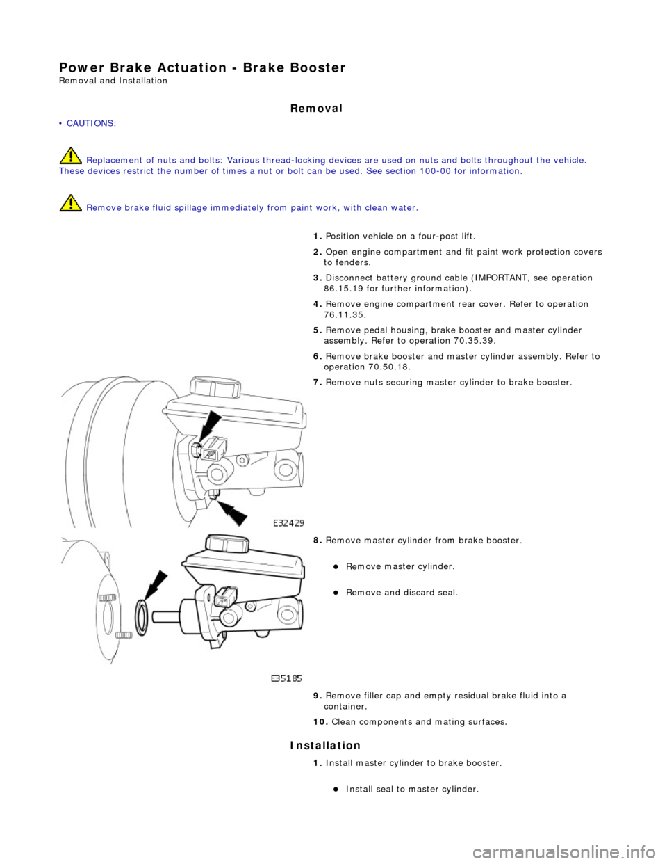
7. R
emove nuts securing master cylinder to brake booster.
8. R
emove master cylinder from brake booster.
Re
move master cylinder.
Remove an
d discard seal.
9. Remove filler cap and empty residual brake fluid into a
container.
10. Clean components and mating surfaces.
1. Install master cylinder to brake booster.
Inst
all seal to master cylinder.
Page 425 of 2490
Power Brake Actuatio
n - Brake Boos
ter and Brake Master Cylinder
Re
moval and Installation
Remov
al
• C
AUTIONS:
Replacement of nuts and bolts: Various thread-locking de vices are used on nuts and bolts throughout the vehicle.
These devices restrict the number of times a nut or bolt can be used. See section 100-00 for information.
Remove brake fluid spilla ge immediately from paint work, with clean water.
1. Position vehi
cle on a four-post lift.
2. Move driver's seat fully rearward.
3. Open engine compartment and fit paint work protection covers
to fenders.
4. Disconnect battery ground cable (IMPORTANT, see operation
86.15.19 for further information).
5. Remove engine compartment rear cover. Refer to operation
76.11.35.
6. Remove pedal housing, brake booster and master cylinder
assembly. Refer to operation 70.35.39.
7. Remove reservoir filler cap and po ur residual brake fluid into a
container. Refit cap.
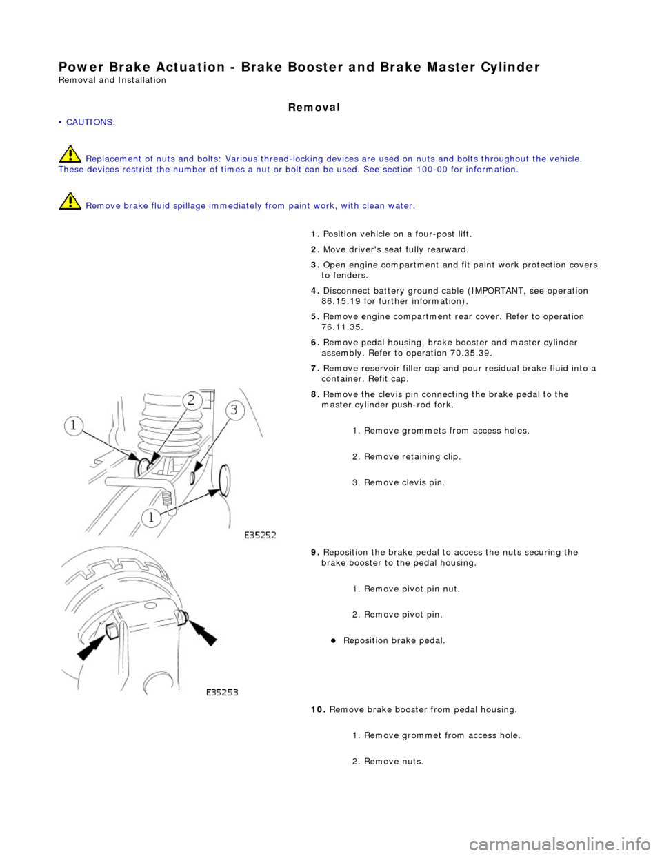
8. R
emove the clevis pin connecting the brake pedal to the
master cylinder push-rod fork.
1. Remove grommets from access holes.
2. Remove retaining clip.
3. Remove clevis pin.
9. Re
position the brake pedal to access the nuts securing the
brake booster to the pedal housing.
1. Remove pivot pin nut.
2. Remove pivot pin.
Reposition brake pedal.
10
.
Remove brake booster from pedal housing.
1. Remove grommet from access hole.
2. Remove nuts.
Page 429 of 2490
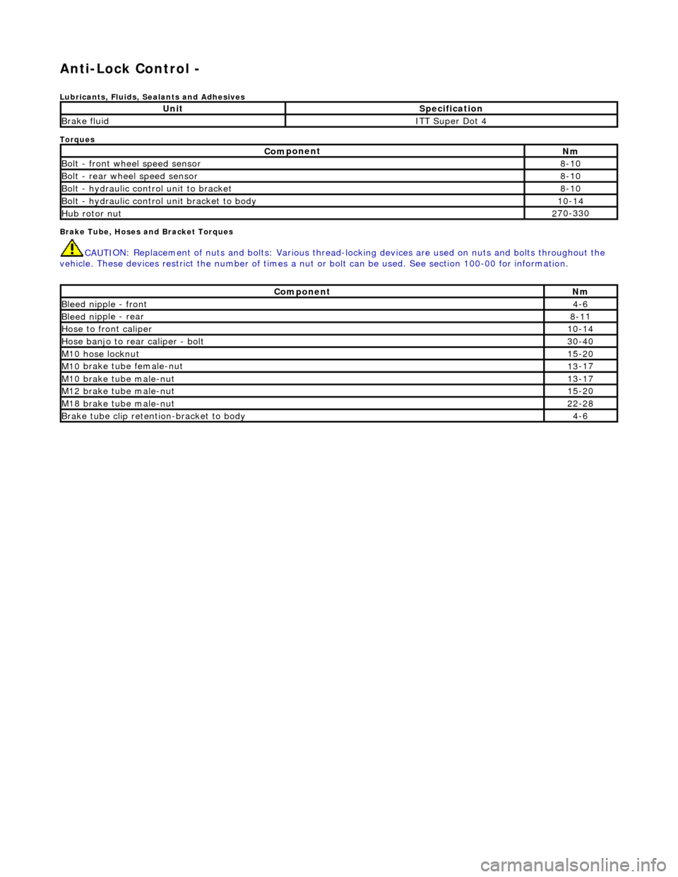
Anti-Lock Control -
Lubri
cants, Fluids, Sealants and Adhesives
Torques
Brake Tube, Hoses and Bracket Torques
CAUTI
ON: Replacement of
nuts and bolts: Various thread-locking devices are used on nuts and bolts throughout the
vehicle. These devices restrict the number of times a nut or bolt can be used. See section 100-00 for information.
UnitS
pecification
Brake flu
id
ITT Supe
r Dot 4
Com
ponent
Nm
Bol
t - front wheel speed sensor
8-
10
Bolt
- rear wheel speed sensor
8-
10
Bo
lt - hydraulic control unit to bracket
8-
10
Bolt -
hydraulic control unit bracket to body
10
-14
Hub rotor nut2
70-330
Com
ponent
Nm
Bleed n
ipple - front
4-
6
Bleed n
ipple - rear
8-1
1
Hose to fr
ont caliper
10
-14
Hose banjo to rear caliper -
bolt
30
-40
M1
0 hose locknut
15
-20
M10
brake tube female-nut
13
-17
M10
brake tube male-nut
13
-17
M12
brake tube male-nut
15
-20
M18
brake tube male-nut
22
-28
Brake tube clip retention
-bracket to body
4-
6
Page 430 of 2490
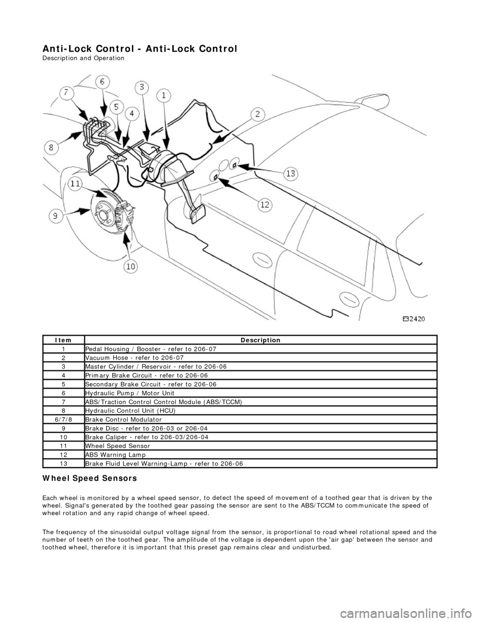
Anti-Lock Control - Anti-Lock Control
Description and Operation
Wheel Spe
ed Sensors
Each
wheel is monitored by a wheel speed se n
sor, to detect the speed of movement of
a toothed gear that is driven by the
wheel. Signal's generate d by the toothed gear passing th e sensor are sent to the ABS/TCCM to communicate the speed of
wheel rotation and any rapid change of wheel speed.
The frequency of the sinusoidal output voltag e signal from the sensor, is proportional to road wheel rotational speed and the
number of teeth on the toothed gear. The amplitude of the volt age is dependent upon the 'air gap' between the sensor and
toothed wheel, therefore it is important that this preset gap remains clear and undisturbed.
Ite
m
De
scr
iption
1Pe
dal Housi
ng / Booster - refer to 206-07
2Vac
u
um Hose - refer to 206-07
3Mas
t
er Cylinder / Reservoir - refer to 206-06
4Pri
m
ary Brake Circuit - refer to 206-06
5Sec
ondary Brake Circuit - refer to 206-06
6Hydraulic
Pump / Motor Unit
7ABS/Traction
Control Control Module (ABS/TCCM)
8Hydraulic Cont
rol Unit (HCU)
6/
7/
8
Br
ak
e Control Modulator
9Brake
Di
sc - refer to 206-03 or 206-04
10Brake
Cali
per - refer to 206-03/206-04
11Wh
ee
l Speed Sensor
12ABS Warning Lamp
13Brake
Fl
uid Level Warning-Lamp - refer to 206-06
Page 434 of 2490
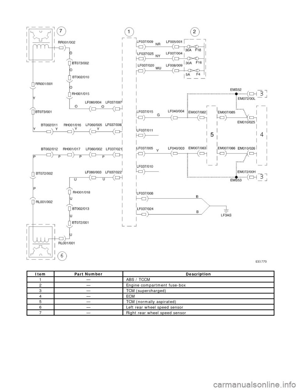
It e
m
Par
t
Number
De
scr
iption
1—ABS /
T
CCM
2—E
n
gine compartment fuse-box
3—TCM (supercha
r
ged)
4—ECM
5—TCM (n ormally
aspirated)
6—Left rear
w
heel speed sensor
7—Ri
ght
rear wheel speed sensor
Page 440 of 2490
Anti-Lock Control - Anti-Lock Brake System (ABS) Module
Remo
val and Installation
Remov
a
l
• C
A
UTIONS:
Replacement of nuts and bolts: Various thread-locking de vices are used on nuts and bolts throughout the vehicle.
These devices restrict the number of times a nut or bolt can be used. See section 100-00 for information.
Remove brake fluid spilla ge immediately from paint work, with clean water.
Sp
ecial Tool(s)
Brake Pedal
H
old Tool
JDS 9013
1. Disc onne
ct battery ground cable (IMPORTANT, see operation
86.15.19 for further information).
2. Position vehicle on a four-post lift.
3. Open engine compartment and fit paint work protection covers
to fenders.
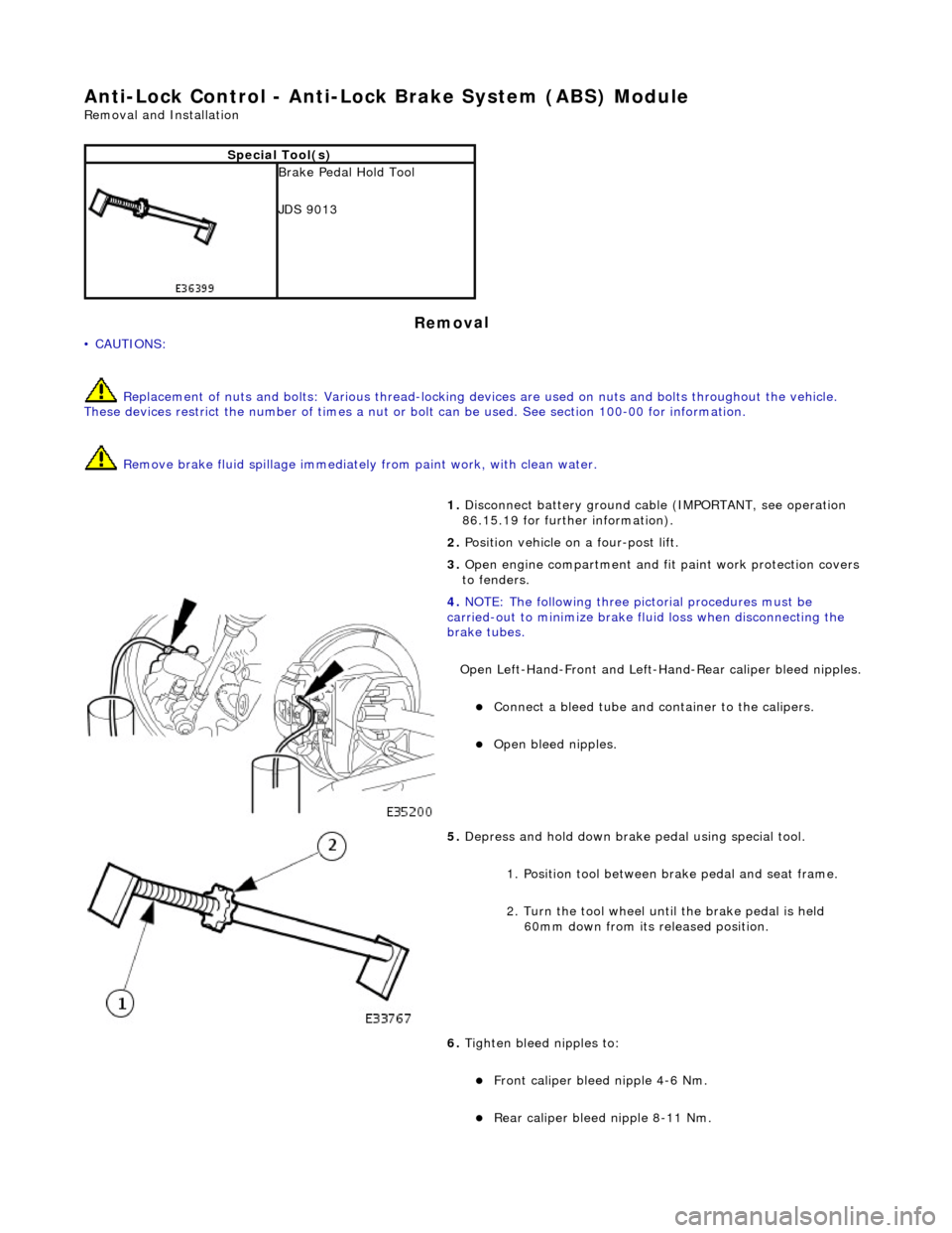
4. NOTE : Th
e following three pictorial procedures must be
carried-out to minimize brake fl uid loss when disconnecting the
brake tubes.
Open Left-Hand-Front and Left-H and-Rear caliper bleed nipples.
Connect a
bleed tube and co
ntainer to the calipers.
Op
en bleed nipples.
5. Depress and hold down brake pedal u s
ing special tool.
1. Position tool between brake pedal and seat frame.
2. Turn the tool wheel unti l the brake pedal is held
60mm down from its released position.
6. Tighten bleed nipples to:
Front caliper blee d nipple 4-6 Nm.
Rear
caliper bleed nip
ple 8-11 Nm.
Page 445 of 2490
Anti-Lock Control - Hydraulic Contro
l Unit (HCU)
Re
moval and Installation
Remov
al
• C
AUTIONS:
Replacement of nuts and bolts: Various thread-locking de vices are used on nuts and bolts throughout the vehicle.
These devices restrict the number of times a nut or bolt can be used. See section 100-00 for information.
Remove brake fluid spilla ge immediately from paint work, with clean water.
S
pecial Tool(s)
Brake Pedal
Hold Tool
JDS 9013
1. Disc
onnect battery ground cable (IMPORTANT, see operation
86.15.19 for further information).
2. Position vehicle on a four-post lift.
3. Open engine compartment and fit paint work protection covers
to fenders.
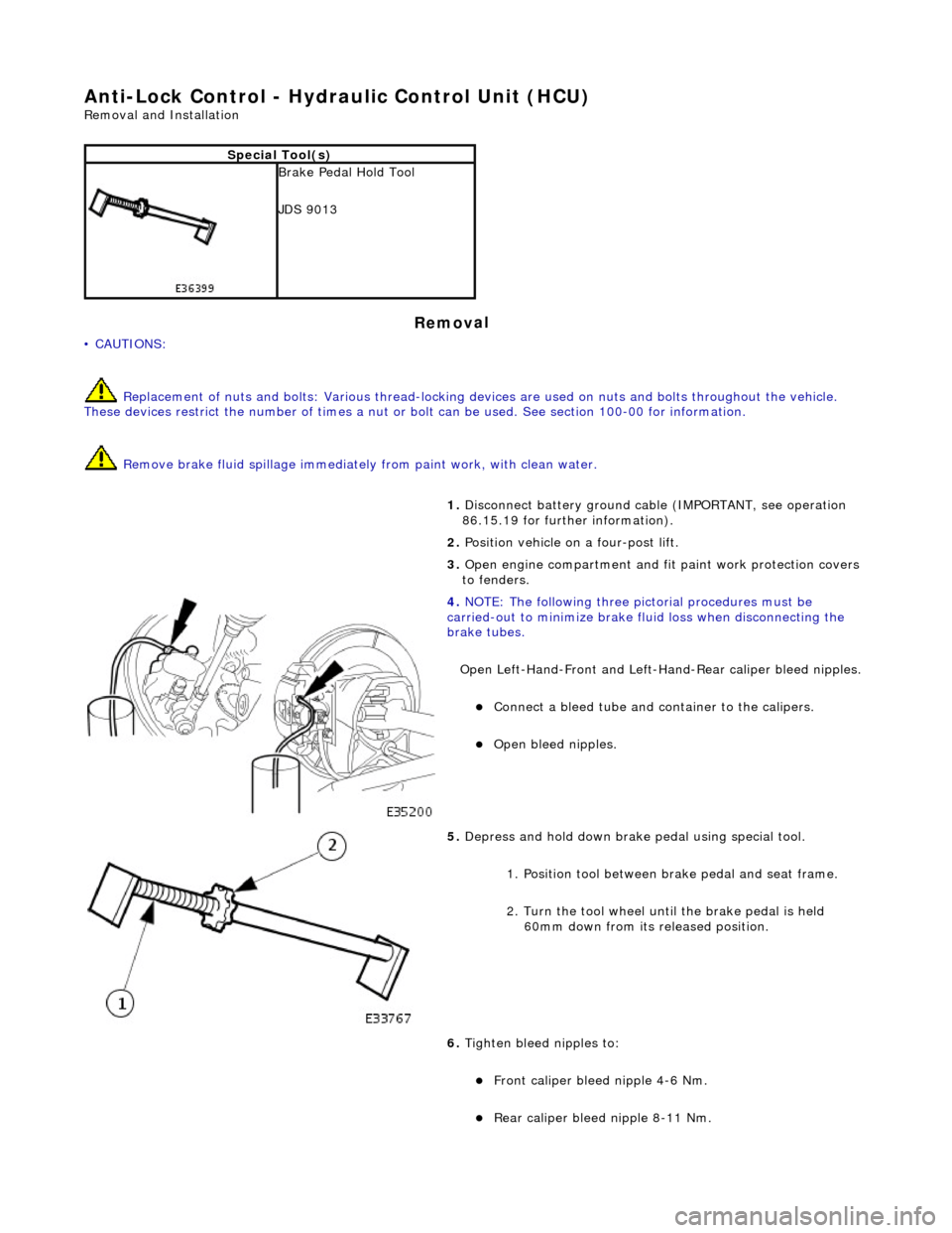
4. NOTE
: The following three pictorial procedures must be
carried-out to minimize brake fl uid loss when disconnecting the
brake tubes.
Open Left-Hand-Front and Left-H and-Rear caliper bleed nipples.
Connect
a bleed tube and co
ntainer to the calipers.
O
pen bleed nipples.
5. Depress and hold down brake pedal u
sing special tool.
1. Position tool between brake pedal and seat frame.
2. Turn the tool wheel unti l the brake pedal is held
60mm down from its released position.
6. Tighten bleed nipples to:
Front caliper blee d nipple 4-6
Nm.
Rear
caliper bleed nipple 8-11 Nm.
Page 450 of 2490

Anti-Lock Control - Wheel Speed Se
nsor Ring
Re
mo
val and Installation
Remov
a
l
CAUTI
O
N: Replacement of
nuts and bolts: Various thread-locking devices are used on nuts and bolts throughout the
vehicle. These devices restrict the number of times a nut or bolt can be used. See section 100-00 for information.
S p
ecial Tool(s)
Hub Holdin
g Tool
2
04-195 (JD 227)
ABS Rotor Nut Socket
2
06-
066A
1.
Op
en engine compartment and
fit paintwork protectors to
fenders.
2. Raise front of vehicle and support on stands. Refer to section
100-02.
3. Remove front wheel. Re fer to section 204-04.
4. Remove front brake disc. Refer to operation 70.10.12.
5. Remove vertical link and hub assembly. Refer to operation
60.25.38.90.
6. Re
move brake-disc shield from vertical link.
1. Remove screws.
2. Remove disc shield.
7. Using special tool, secure vertical link and hub assembly in a
vice.
Secure special tool
in a vice.
Posit
i
on hub in tool.
Fit and
tighten wheel nuts.
Page 457 of 2490
•
NOTE: The following steps must be carried out with assistance.
1. 1. With the wheels in the straight ahead po sition, gently turn the steering wheel to the left and the right to check for
free play.
2. 2. Free play should be between 0 and 6 mm (0 and 0.24 in) at the steering wheel rim. If the free play exceeds this
limit, either the ball joints are worn, the lower steering column joints are worn or the backlash of the steering gear
is excessive.
CAUTION: DO NOT attempt to adjust the stee ring gear yoke. Failure to follow this instruction will result in the steering
gear warranty to become invalid.
3. 3. The backlash of the steering gear cannot be adjusted, in stall a new steering gear. For additional information,
REFER to Section 211
-0
2 Power Steering
.
4. 4. Grasp the steering wheel
firm
ly and move it up and down and to the left and right without turning the wheel to
check for column bearing wear, steering wheel or steering column. For additional information,
REFER to Section 211
-0
4 Steering Column
.
Power Steering Fluid Condition Check
1.
1. R
un the engine for 2 minutes.
2. 2. Check the power steering fluid system level.
3. 3. Observe the color and the odor. The color under normal circumstances should be dark reddish, not brown or
black.
4. 4. Allow the fluid to drip onto a faci al tissue and examine the stain.
5. 5. If evidence of solid material is foun d, the power steering fluid system should be drained for further inspection.
6. 6. If fluid contamination or steering co mponent failure is confirmed by the se diment in the power steering fluid
system, REFER to Steering Fault Diagnosis by Symptom Charts in this section.
Power Steer
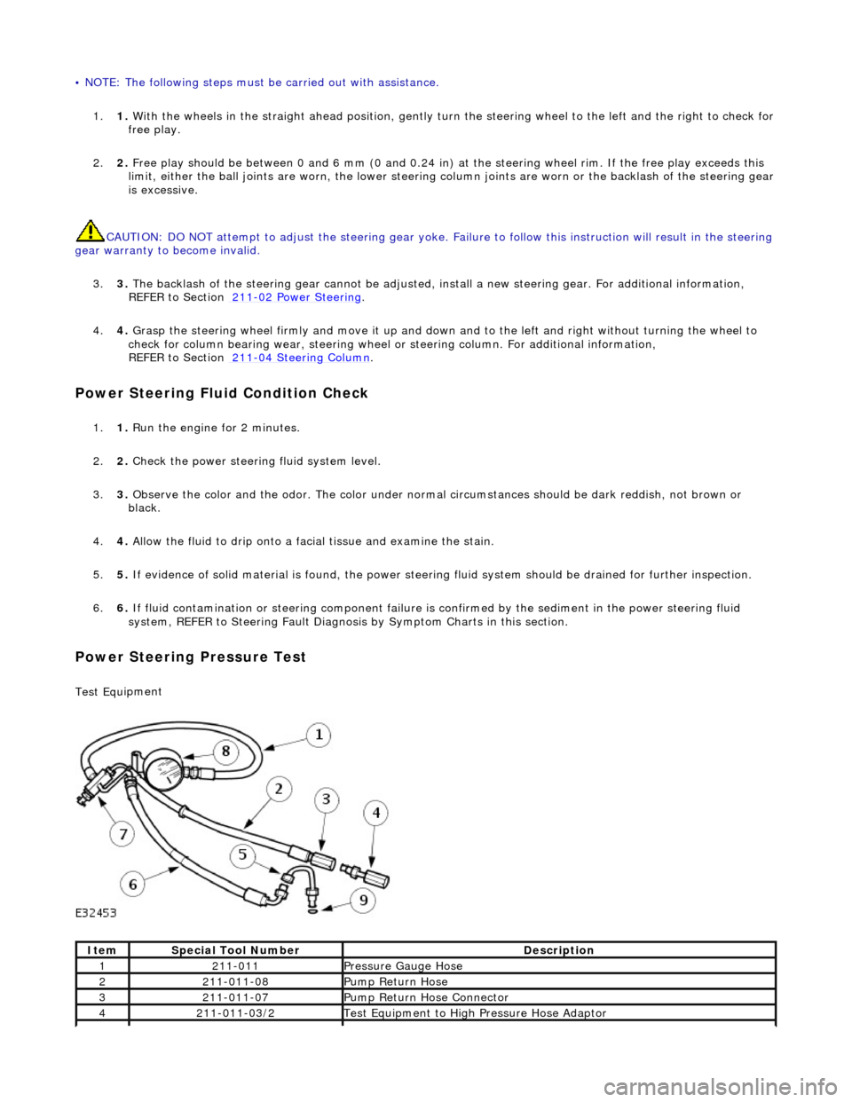
ing Pressure Test
Test Equ
ipment
It
em
S
pecial Tool Number
De
scription
12
11-011
Pres
sure Gauge Hose
221
1-011-08
Pump Return Hose
321
1-011-07
Pump Return Hose Connector
42
11-011-03/2
Test Equ
ipment to High
Pressure Hose Adaptor