vi number JAGUAR X308 1998 2.G Workshop Manual
[x] Cancel search | Manufacturer: JAGUAR, Model Year: 1998, Model line: X308, Model: JAGUAR X308 1998 2.GPages: 2490, PDF Size: 69.81 MB
Page 527 of 2490
E
ngine Management System Components
Electronic Throt
tle
The
electronic throttle assembly, in resp
onse to signals from both the driver and the ECM, adjusts idle speed, sets the
throttle valve to the position requested by the driver's accelerator / throttle pedal, cruise and traction control, power
limitation and catalyst warm-up.
Mass
Air Flow Meter
The sensor i
s located in the air flow mete
r assembly and outputs an analogue voltag e to the ECM. This sensor measures air
flow into the engine inlet system and is calibrated to measure kg / hour.
In
take Air Temperature
Th
e intake air temperature sensor is loca
ted in the air flow meter assembly and outputs an analogue voltage to the ECM.
The ECM will substitute a default value eq ual to 50°C should this sensor fail.
Fuel Injectors
The eigh
t bottom fed fuel injectors are located in the fuel rails. Th
e fuel injectors are electromagnetic solenoid valves
controlled by the ECM. The pulse time for the injector combined with the fuel pr essure determines the volume of fuel
injected to the manifold.
Fue
l Delivery
The fu
el pump provides fuel to the fuel rail where the circulat
ing pressure is controlled by a pressure regulator valve; excess
fuel is returned to the fuel tank.
The pressure regulator valve is controlled by manifold depression so that fuel delivery pressure is maintained at
approximately 3 bar above manifold pressure.
Fuel Pump
Relay
The ECM controls thi
s component for normal
engine running. The security system may disable this relay via communication
with the ECM.
Fuel Lev
el Sensing
The tank fuel
is measured by the fuel le
vel sensor . This signal is used by the ECM as an in put to certain diagnostics.
Eva
porative Valve
Excess vapour
formed in the fuel tank is
absorbed into the evaporative emission pu rge control canister. While the engine is
running, the fuel absorbed in the canister is gradually purged back into the engine. The rate of purging is governed by
engine operating conditions and vapour concentration level. Operating conditions which affect the purge rate are:
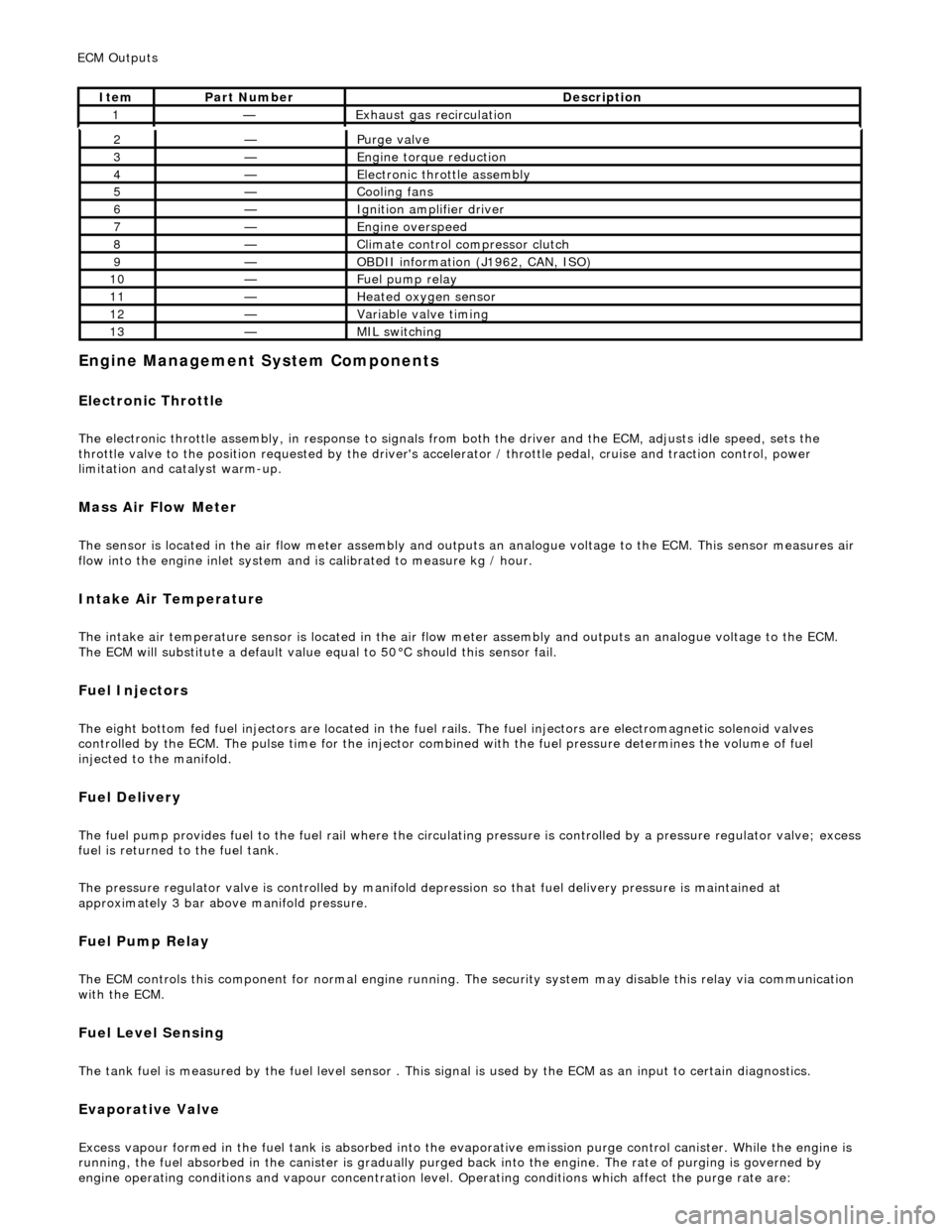
2—Purge
valve
3—Engine
torque reduction
4—E
lectronic throttle assembly
5—Coo
ling fans
6—Ignition amplifier driver
7—Engine overspeed
8—Cli
mate control compressor clutch
9—O
BDII information (J1962, CAN, ISO)
10—F
uel pump relay
11—Heat
ed oxygen sensor
12—Vari
able valve timing
13—MIL sw
itching
ECM Out
puts
It
em
Par
t Number
De
scription
1—Exhaus
t gas recirculation
Page 615 of 2490
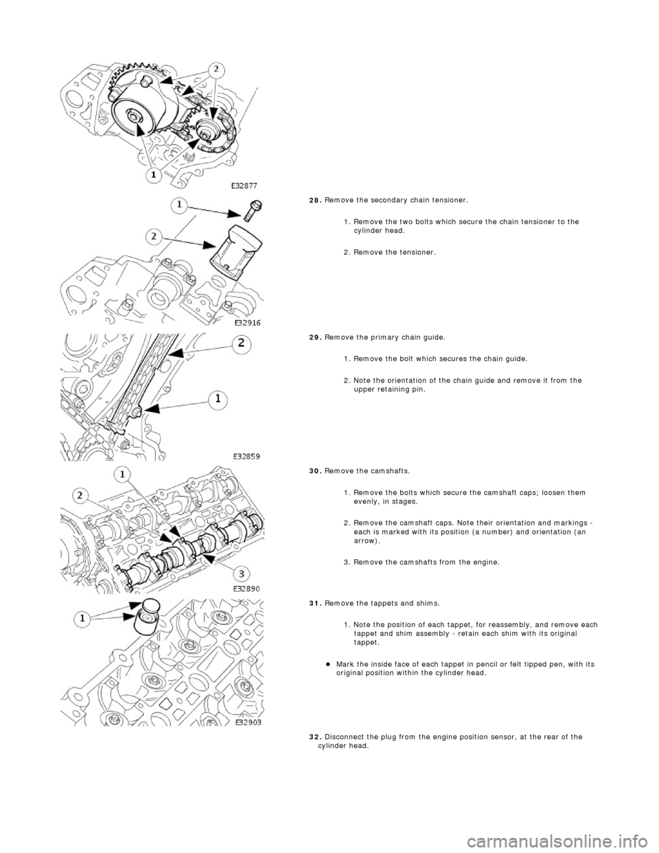
28
.
Remove the secondary chain tensioner.
1. Remove the two bolts which secure the chain tensioner to the cylinder head.
2. Remove the tensioner.
29
.
Remove the primary chain guide.
1. Remove the bolt which secures the chain guide.
2. Note the orientation of the chain guide and remove it from the upper retaining pin.
30
.
Remove the camshafts.
1. Remove the bolts which secure the camshaft caps; loosen them evenly, in stages.
2. Remove the camshaft caps. Note their orientation and markings -
each is marked with its position (a number) and orientation (an
arrow).
3. Remove the camshafts from the engine.
31
.
Remove the tappets and shims.
1. Note the position of each tappet, for reassembly, and remove each
tappet and shim assembly - retain each shim with its original
tappet.
Mark
the inside face of each tappet in pencil or felt tipped pen, with its
original position within the cylinder head.
32. Disconnect the plug from the engine position sensor, at the rear of the
cylinder head.
Page 631 of 2490
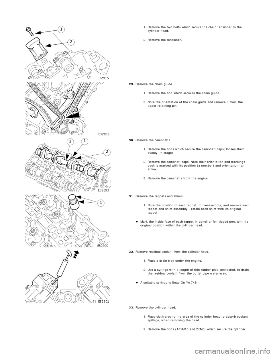
1.
Remove the two bolts which secure the chain tensioner to the
cylinder head.
2. Remove the tensioner.
29
.
Remove the chain guide.
1. Remove the bolt which secures the chain guide.
2. Note the orientation of the chain guide and remove it from the upper retaining pin.
30
.
Remove the camshafts.
1. Remove the bolts which secure the camshaft caps; loosen them evenly, in stages.
2. Remove the camshaft caps. Note their orientation and markings -
each is marked with its position (a number) and orientation (an
arrow).
3. Remove the camshafts from the engine.
31
.
Remove the tappets and shims.
1. Note the position of each tappet, for reassembly, and remove each
tappet and shim assembly - retain each shim with its original
tappet.
Mark
the inside face of each tappet in pencil or felt tipped pen, with its
original position within the cylinder head.
32
.
Remove residual coolant from the cylinder head.
1. Place a drain tray under the engine.
2. Use a syringe with a length of thin rubber pipe connected, to drain the residual coolant from the outlet pipe water-way.
A s
uitable syringe is Snap On YA 745.
33. Remove the cylinder head.
1. Place cloth around the area of th e cylinder head to absorb coolant
spillage, when removing the head.
2. Remove the bolts (10xM10 and 2xM8) which secure the cylinder
Page 660 of 2490
Engine - Exhaust Camshaft LH
In-vehicle Repair
Removal
Installation
1. Open the engine compartment and fit paintwork protection
sheets.
2. Set the engine compartment cover to the service access
position.
3. Disconnect the batt ery ground cable.
Remove the battery cover.
4. Remove Exhaust Camshaft Sp rocket. Refer to Operation
12.65.74.
5. Remove the camshaft locking tool 303 - 530 (fitted for
previous operation).
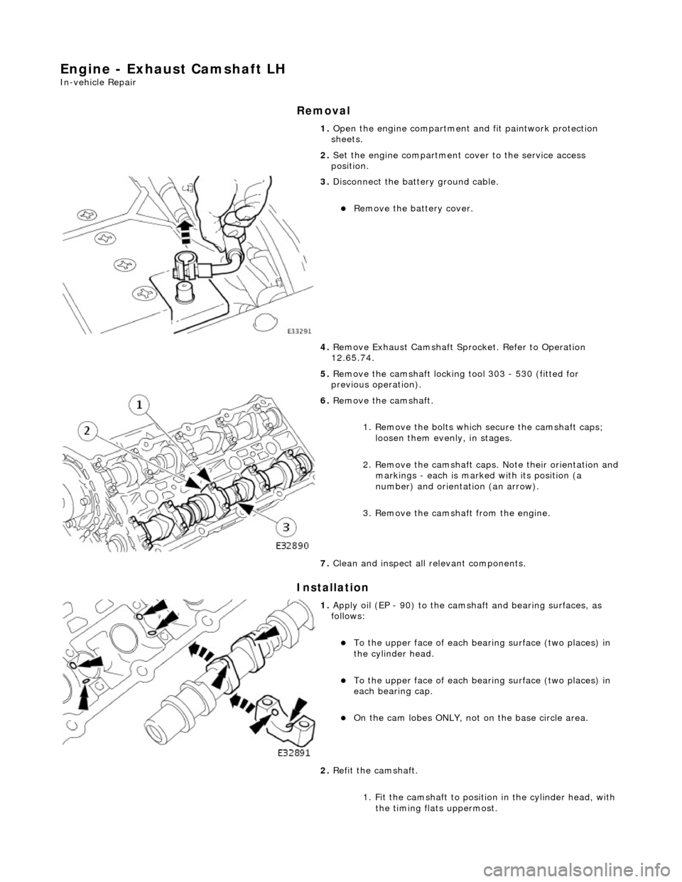
6. Remove the camshaft.
1. Remove the bolts which secure the camshaft caps; loosen them evenly, in stages.
2. Remove the camshaft caps. Note their orientation and
markings - each is marked with its position (a
number) and orientation (an arrow).
3. Remove the camshaft from the engine.
7. Clean and inspect all relevant components.
1. Apply oil (EP - 90) to the cams haft and bearing surfaces, as
follows:
To the upper face of each be aring surface (two places) in
the cylinder head.
To the upper face of each be aring surface (two places) in
each bearing cap.
On the cam lobes ONLY, not on the base circle area.
2. Refit the camshaft.
1. Fit the camshaft to position in the cylinder head, with the timing flats uppermost.
Page 662 of 2490
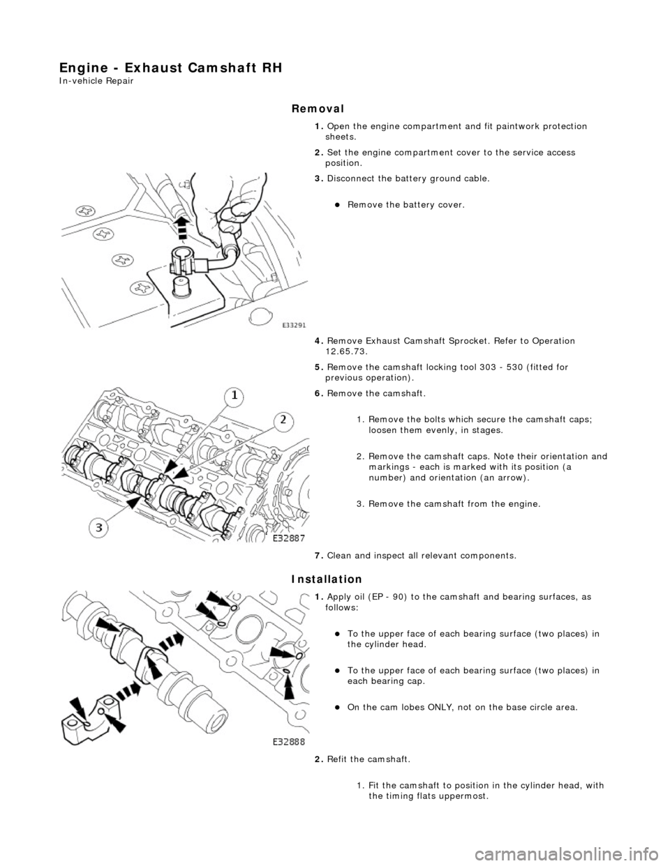
Engine - Exhaust Camshaft RH
In-vehicle Repair
Removal
Installation
1. Open the engine compartment and fit paintwork protection
sheets.
2. Set the engine compartment cover to the service access
position.
3. Disconnect the batt ery ground cable.
Remove the battery cover.
4. Remove Exhaust Camshaft Sp rocket. Refer to Operation
12.65.73.
5. Remove the camshaft locking tool 303 - 530 (fitted for
previous operation).
6. Remove the camshaft.
1. Remove the bolts which secure the camshaft caps; loosen them evenly, in stages.
2. Remove the camshaft caps. Note their orientation and
markings - each is marked with its position (a
number) and orientation (an arrow).
3. Remove the camshaft from the engine.
7. Clean and inspect all relevant components.
1. Apply oil (EP - 90) to the cams haft and bearing surfaces, as
follows:
To the upper face of each be aring surface (two places) in
the cylinder head.
To the upper face of each be aring surface (two places) in
each bearing cap.
On the cam lobes ONLY, not on the base circle area.
2. Refit the camshaft.
1. Fit the camshaft to position in the cylinder head, with the timing flats uppermost.
Page 700 of 2490
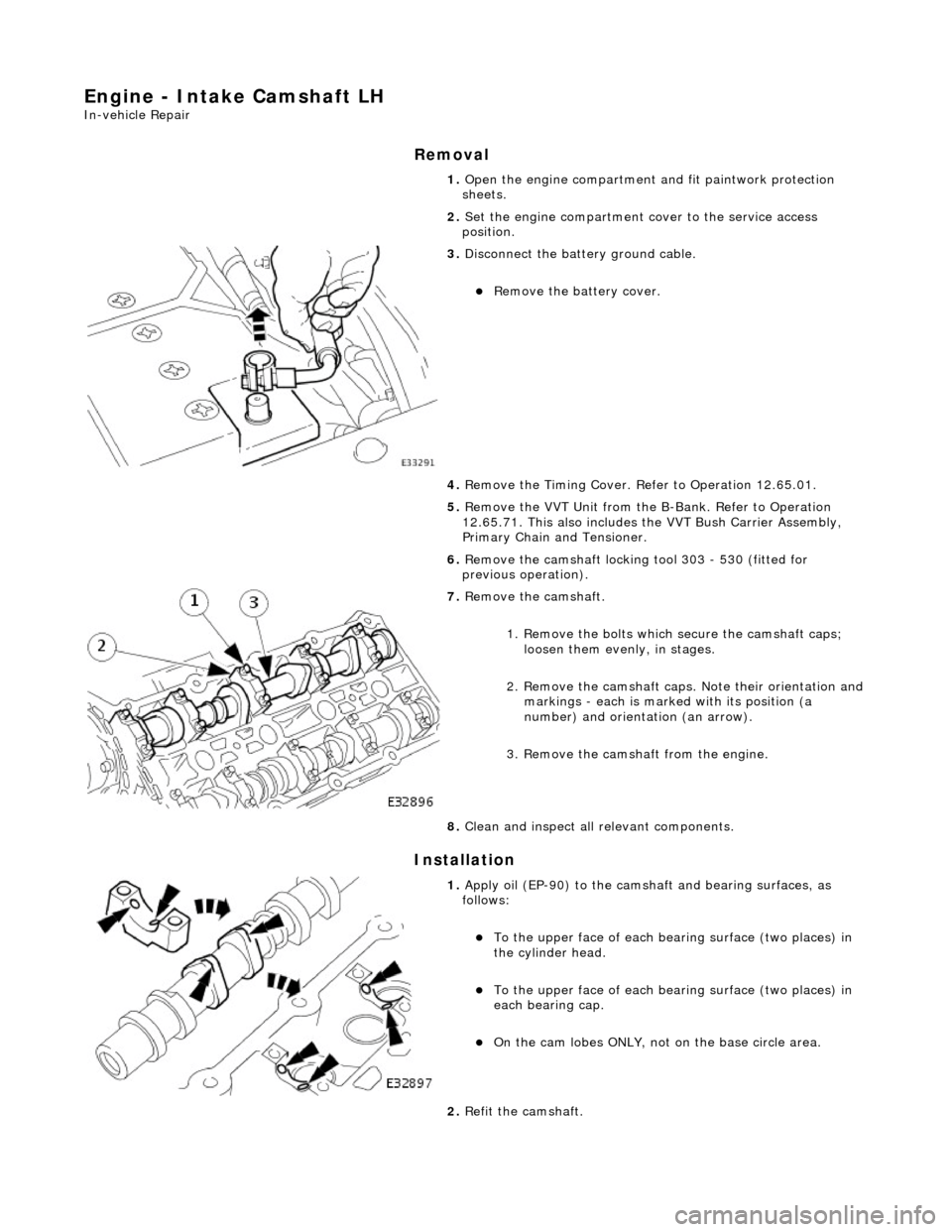
Engine - Intake Camshaft LH
In-vehicle Repair
Removal
Installation
1. Open the engine compartment and fit paintwork protection
sheets.
2. Set the engine compartment cover to the service access
position.
3. Disconnect the batt ery ground cable.
Remove the battery cover.
4. Remove the Timing Cover. Re fer to Operation 12.65.01.
5. Remove the VVT Unit from the B-Bank. Refer to Operation
12.65.71. This also includes the VVT Bush Carrier Assembly,
Primary Chain and Tensioner.
6. Remove the camshaft locking tool 303 - 530 (fitted for
previous operation).
7. Remove the camshaft.
1. Remove the bolts which secure the camshaft caps; loosen them evenly, in stages.
2. Remove the camshaft caps. Note their orientation and
markings - each is marked with its position (a
number) and orientation (an arrow).
3. Remove the camshaft from the engine.
8. Clean and inspect all relevant components.
1. Apply oil (EP-90) to the camsha ft and bearing surfaces, as
follows:
To the upper face of each be aring surface (two places) in
the cylinder head.
To the upper face of each be aring surface (two places) in
each bearing cap.
On the cam lobes ONLY, not on the base circle area.
2. Refit the camshaft.
Page 702 of 2490
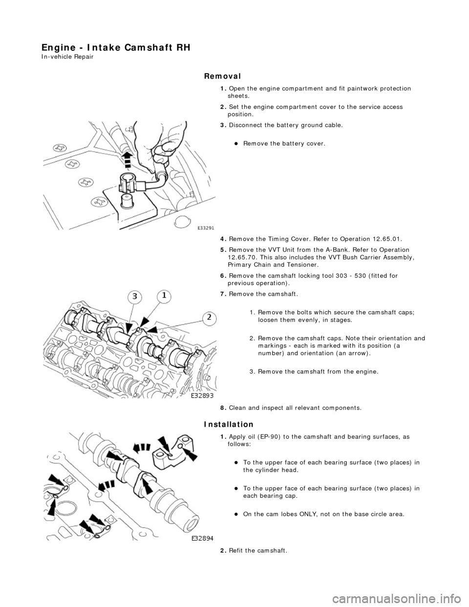
Engine - Intake Camshaft RH
In-vehicle Repair
Removal
Installation
1. Open the engine compartment and fit paintwork protection
sheets.
2. Set the engine compartment cover to the service access
position.
3. Disconnect the batt ery ground cable.
Remove the battery cover.
4. Remove the Timing Cover. Re fer to Operation 12.65.01.
5. Remove the VVT Unit from the A-Bank. Refer to Operation
12.65.70. This also includes the VVT Bush Carrier Assembly,
Primary Chain and Tensioner.
6. Remove the camshaft locking tool 303 - 530 (fitted for
previous operation).
7. Remove the camshaft.
1. Remove the bolts which secure the camshaft caps; loosen them evenly, in stages.
2. Remove the camshaft caps. Note their orientation and
markings - each is marked with its position (a
number) and orientation (an arrow).
3. Remove the camshaft from the engine.
8. Clean and inspect all relevant components.
1. Apply oil (EP-90) to the camsha ft and bearing surfaces, as
follows:
To the upper face of each be aring surface (two places) in
the cylinder head.
To the upper face of each be aring surface (two places) in
each bearing cap.
On the cam lobes ONLY, not on the base circle area.
2. Refit the camshaft.
Page 932 of 2490
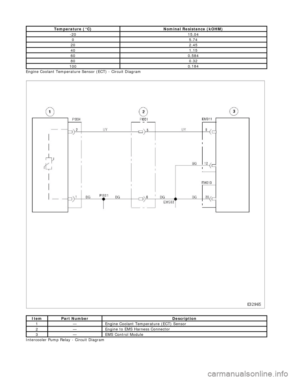
Engi
ne Coolant Temperature Sensor (ECT) - Circuit Diagram
Intercooler Pump Relay - Circuit Diagram
T emper
ature (°C)
No
mi
nal Resistance (kOHM)
-2
015 .0
4
05.7
4
202.45
401.15
600.
584
800.3
2
1000.
184
ItemPar
t
Number
De
scrip
tion
1—Eng
i
ne Coolant Temperature (ECT) Sensor
2—Eng
i
ne to EMS Harness Connector
3—EMS Con
trol Modu
le
Page 933 of 2490
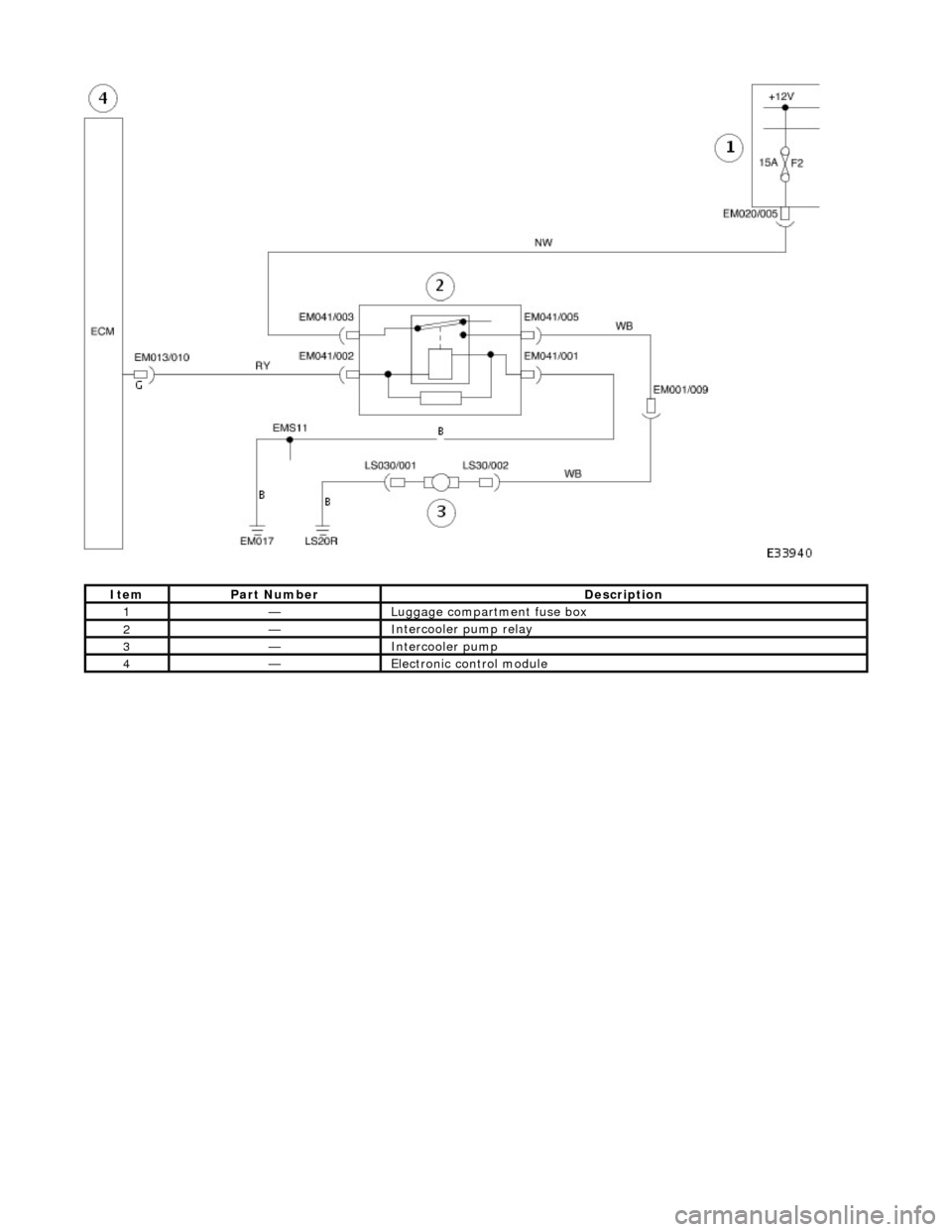
ItemPar
t Number
De
scription
1—Lug
gage compartment fuse box
2—I
ntercooler pump relay
3—I
ntercooler pump
4—Electr
onic control module
Page 1014 of 2490
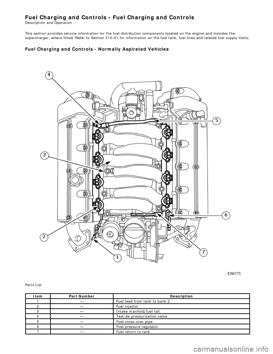
Fuel Char
ging and Controls - Fuel Charging and Controls
Description an
d Operation
This section provides service informatio n for the fuel distribution components located on the engine and includes the
supercharger, where fitted. Refer to Section 310-01 for informatio n on the fuel tank, fuel lines and related fuel supply items.
Fuel Charging and Controls -
Normally Aspirated Vehicles
P
a
rts List
It
e
m
Par
t
Number
De
scr
iption
1—F
u
el feed from tank to bank 2
2—Fue
l
injector
3—Inta
k
e manifold/fuel rail
4—Te
st
/de-pressurization valve
5—F
u
el cross-over pipe
6—F
u
el pressure regulator
7—F
u
el return to tank