JAGUAR X308 1998 2.G Workshop Manual
X308 1998 2.G
JAGUAR
JAGUAR
https://www.carmanualsonline.info/img/21/7640/w960_7640-0.png
JAGUAR X308 1998 2.G Workshop Manual
Trending: battery location, AUX, 76.22.78, Belt T, transmission fluid reservoir, battery replacement, remote control
Page 1491 of 2490
Automatic Transmission/Transaxle External Controls - 4.0L NA V8 -
AJ27/3.2L NA V8 - AJ 26 - Selector Lever Indicator Assembly
Removal and Installation
Removal
Installation
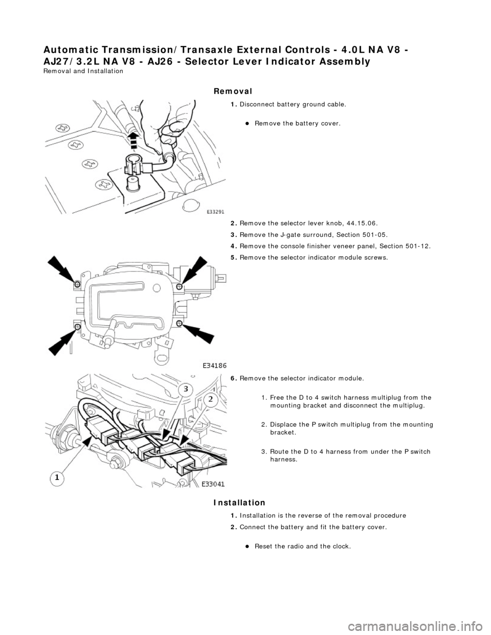
1. Disconnect battery ground cable.
Remove the battery cover.
2. Remove the selector lever knob, 44.15.06.
3. Remove the J-gate surround, Section 501-05.
4. Remove the console finisher ve neer panel, Section 501-12.
5. Remove the selector indicator module screws.
6. Remove the selector indicator module.
1. Free the D to 4 switch harness multiplug from the mounting bracket and disc onnect the multiplug.
2. Displace the P switch multiplug from the mounting bracket.
3. Route the D to 4 harnes s from under the P switch
harness.
1. Installation is the revers e of the removal procedure
2. Connect the battery and fit the battery cover.
Reset the radio and the clock.
Page 1492 of 2490
Automatic Transmission/Transaxle External Controls - 4.0L NA V8 -
AJ27/3.2L NA V8 - AJ26 - Se lector Lever Indicator Disc
Removal and Installation
Removal
Installation
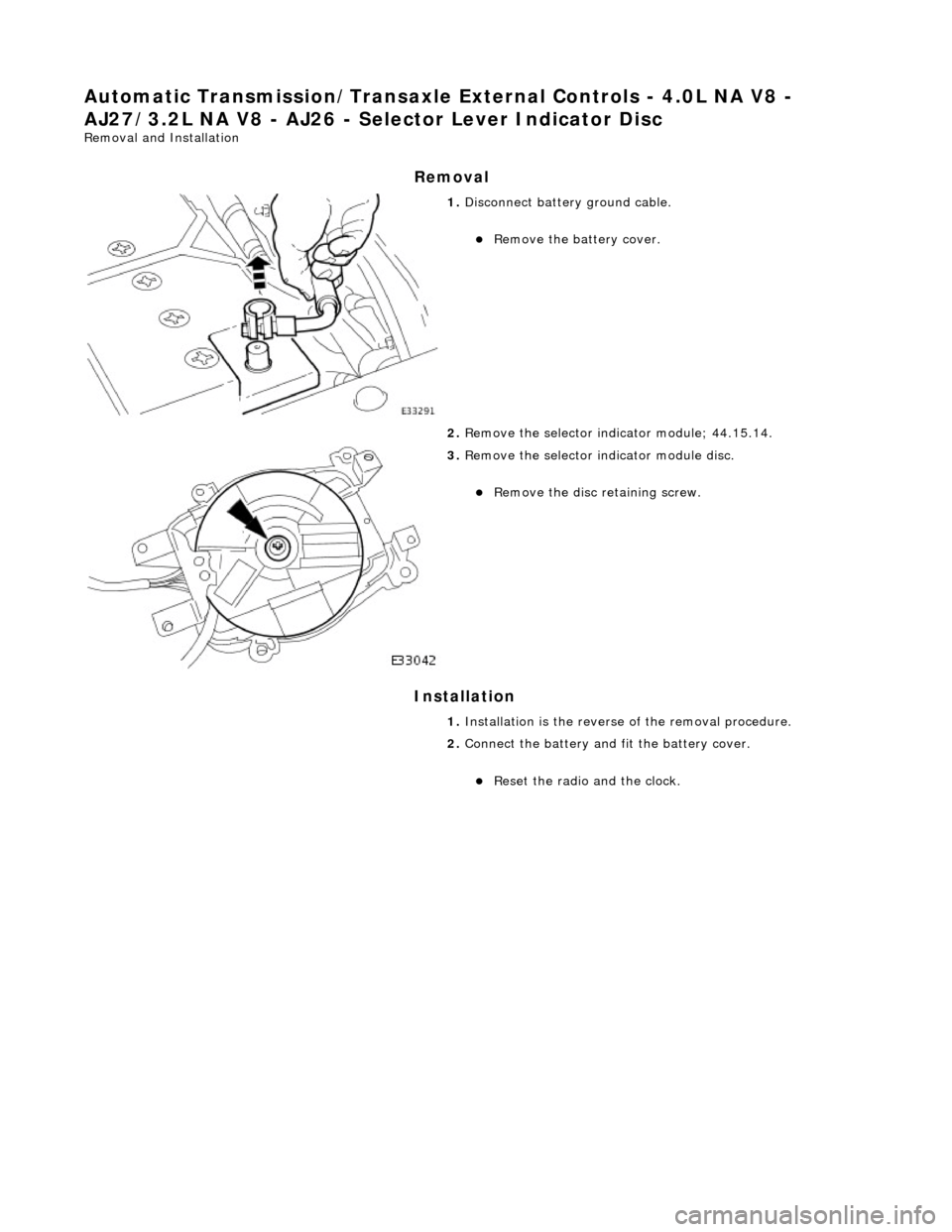
1. Disconnect battery ground cable.
Remove the battery cover.
2. Remove the selector indicator module; 44.15.14.
3. Remove the selector indicator module disc.
Remove the disc retaining screw.
1. Installation is th e reverse of the re moval procedure.
2. Connect the battery and fit the battery cover.
Reset the radio and the clock.
Page 1493 of 2490
Automatic Transmission/Transaxle External Controls - 4.0L NA V8 -
AJ27/3.2L NA V8 - AJ26 - Selector Lever Switch
Removal and Installation
Removal
Installation
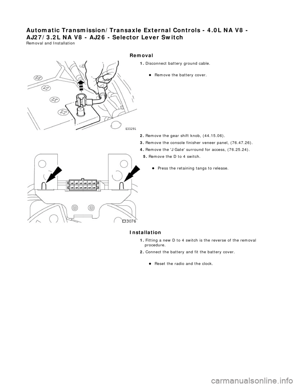
1. Disconnect battery ground cable.
Remove the battery cover.
2. Remove the gear shift knob, (44.15.06).
3. Remove the console finisher veneer panel, (76.47.26).
4. Remove the 'J Gate' surroun d for access, (76.25.24).
5. Remove the D to 4 switch.
Press the retaining tangs to release.
1. Fitting a new D to 4 switch is the reverse of the removal
procedure.
2. Connect the battery and fit the battery cover.
Reset the radio and the clock.
Page 1494 of 2490
Automatic Transmission/Transaxle External Controls - 4.0L NA V8 -
AJ27/3.2L NA V8 - AJ26 - Selector Lever Knob
Removal and Installation
Removal
Installation
1. Remove the select or lever knob.
1. Slacken the ferrule, rotate clock-wise.
2. Rotate the knob coun ter-clockwise to remove.
1. Refer to the illustration
1. Fit the knob.
2. Tighten the ferru le to the specified torque figure.
Page 1495 of 2490
Automatic Transmission/Transaxle External Controls - 4.0L NA V8 -
AJ27/3.2L NA V8 - AJ26 - Selector Lever Assembly
Disassembly and Assembly
1. Disconnect battery ground cable.
Remove the battery cover.
2. Remove the shift le ver knob, 44.15.06.
3. Remove the J-gate surround, Section 501-05.
4. Remove the console finisher ve neer panel, Section 501-12.
5. Remove the center console assembly, Section 501-12.
6. Remove the indicator module, 44.15.14.
7. Detach the selector cable from the gear shift assembly.
1. Remove the inner cable to selector lever nut.
2. Slacken one outer cable locknut, keeping one positioned for reference on reassembly.
8. Remove the gear shift assembly.
Remove the four fixings.
9. Remove the slide plate.
Remove the four screws.
Page 1496 of 2490
10. Remove the slide bl ock/shaft assembly.
11. Remove the gearshift interlock solenoid actuating lever.
1. Remove the actu ating lever cover.
2. Remove the actuatin g lever securing nut.
12. Remove the shift lever as sembly from the housing.
Remove the washer from the pivot shaft.
13. Disassemble the shift mechanism.
1. Remove the return spring.
2. Remove the pivot shaft nut, washer and pivot shaft.
3. Remove the pivot bracket, detent plate and washer.
Page 1497 of 2490
4. Remove the ball and spring.
14. Clean all components.
15. Reassemble the shift mechanism.
1. Apply grease and install the detent ball and spring.
2. Apply grease to the pivot bracket and install the bracket, detent plate and washer.
3. Install the pivot sh aft, washer and nut.
4. Apply grease and locate the return spring.
16. Fit the shift lever assembly to the housing.
Apply grease to the lever pivot and install the pivot
washer.
17. Install the gearshift interloc k solenoid actuating lever.
1. Secure the actu ating lever nut.
2. Fit the actuating lever cover.
18. Install the slide block / shaft assembly.
Clean the slide block and shaft.
Apply grease to the shaft.
Page 1498 of 2490
19. Inst
all the slide plate.
Install
the four sl
ide plate screws.
20 . Fi
t the gear shift assembly.
Inst
all th
e four nuts.
21 . Asse
mble the cable to the gear shift assembly.
1. Locate the outer cable.
2. Fit and tighten the cable securing nut to the specified torque figure.
22. Adjust, or verify, the cable in accordance with 44.15.07.
23. Further installation is the reve rse of the removal procedure.
24. Connect the battery and fit the battery cover.
Reset the radio an
d the clock.
Page 1499 of 2490
Automatic Transmission/Transaxle External Controls - 4.0L SC V8 - AJ26 -
External Controls
Description and Operation
Introduction
Operator gearshift control is effected by:
The selector lever Accelerator pedal position Kickdown The mode switch
Operator's Selector Module ('J' Gate)
Page 1500 of 2490
ItemPart NumberDescription
1—Gear selector lever
2—Access blank - Gear-shift interlock solenoid
3—Connector - DLS
4—Dual Linear Switch (DLS)
5—Connector - Park position switch
6—Connector - Illumination module
Trending: power seat, 12.65.63, radio aerial, Relay, automatic gear, battery replacement, AF sensors


