AUTOMATIC JAGUAR X308 1998 2.G User Guide
[x] Cancel search | Manufacturer: JAGUAR, Model Year: 1998, Model line: X308, Model: JAGUAR X308 1998 2.GPages: 2490, PDF Size: 69.81 MB
Page 274 of 2490
A c
ontrol orifice in the pump rod determines the levelling height. When the damper is compressed, this orifice is covered.
When the damper extends, the control orif ice is uncovered, pressure is released to the low pressure oil reservoir and the
system ceases to rise. When the vehicle is high after unloading, the opened control or ifice allows fluid to be returned to the
low pressure oil reservoir, and the suspensi on returns to its normal unladen height.
Ad
aptive Damping
•
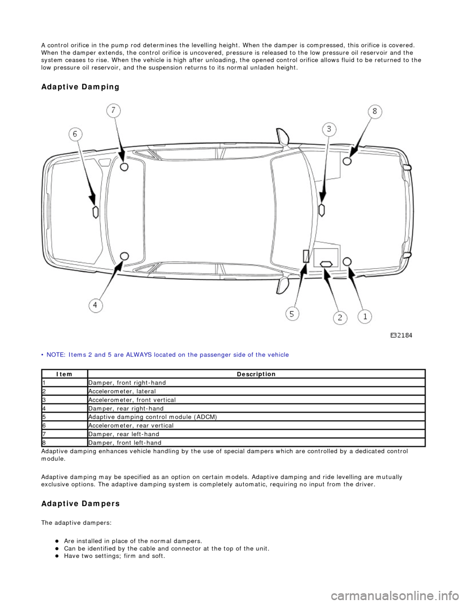
NOTE: Items 2 and 5 are ALWAYS located
on the passenger side of the vehicle
Adaptive damping enhances vehicle handli ng by the use of special dampers which are controlled by a dedicated control
module.
Adaptive damping may be specified as an option on certai n models. Adaptive damping and ride levelling are mutually
exclusive options. The adaptive damping system is completely automatic, requiring no input from the driver.
A d
aptive Dampers
The adaptiv
e dampers:
пЃ¬Are inst
alled in place of the normal dampers.
пЃ¬Can be identified
by the cable and connector at the top of the unit.
пЃ¬Have two settings; fi
rm and so
ft.
It
e
m
De
scr
iption
1Dam
p
er, front right-hand
2Accel
e
rometer, lateral
3Accel
e
rometer,
front vertical
4D
a
mper, rear right-hand
5Adaptive dampin
g control module (A
DCM)
6Accel
e
rometer, rear vertical
7D
amper, rear l
eft-hand
8Dam
p
er, front left-hand
Page 297 of 2490

I
nstallation
10
.
Clean the seal counterbore.
1. Installation is the re verse of the removal procedure, noting the
following;
2. Lightly lubricate the seal O/D.
3. Chec
k for the correct assembly condition.
пЃ¬E
nsure that the seal, Ryton
ring and backing are aligned
and in contact with each other.
4. NOTE: Correct pinion seal location is automatic.
`Pull' the pinion flan ge / seal assembly down with the pinion
nut - do not hammer the flange.
5. R
efer to the illustration.
пЃ¬R
otate the pinion prior to final tightening.
пЃ¬St
ake the nut to the pinion.
6. Check the pinion drive flange axial run-out.
пЃ¬0,
08 mm MAX TIR.
пЃ¬If t
his specification is exceeded, renew the flange / seal
assembly.
Page 507 of 2490
The driver air bag is moun
ted below the horn operat
ing pad area, adjacent to the steering wheel hub.
For air bag safety and service information, refer to Section 501
-20A Safety Belt
System
Sectio
n
501
-2
0B Supplemental
Re
straint System
.
Upper Steering Column
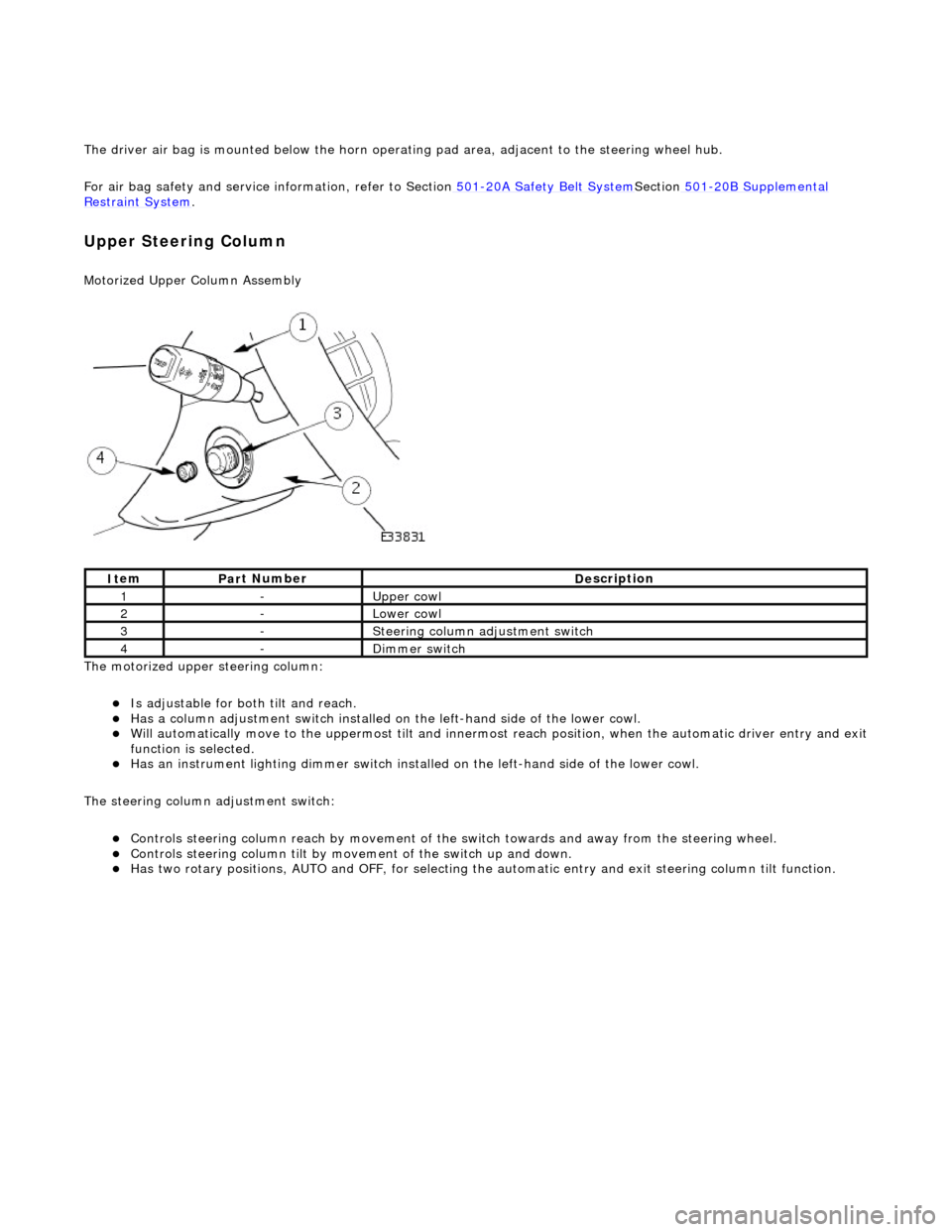
Motorized Upper Colu
mn Assembly
The motorized upper steering column:
пЃ¬Is adjustable for both til
t and reach.
пЃ¬Has a col
umn adjustment switch installed on
the left-hand side of the lower cowl.
пЃ¬W
ill automatically move to the uppermost tilt and innermost reach position, when the automatic driver entry and exit
function is selected.
пЃ¬Has an instrument li
ghti
ng dimmer switch installed on the left-hand side of the lower cowl.
The steering column adjustment switch:
пЃ¬Controls steeri
ng column reach by
movement of the switch towards an d away from the steering wheel.
пЃ¬Controls steeri
ng column tilt by mo
vement of the switch up and down.
пЃ¬Has two
rotary positions, AUTO and OFF, for selecting the
automatic entry and exit steering column tilt function.
It
em
Par
t Number
De
scription
1-Upper
cowl
2-Lower cowl
3-Ste
ering column adjustment switch
4-Di
mmer switch
Page 508 of 2490
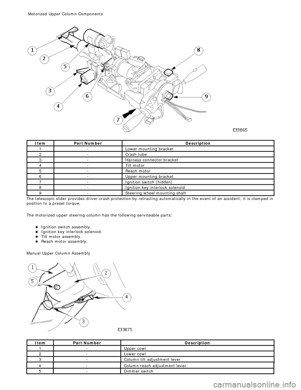
The te
lescopic slider provides driver crash
protection by retracting automatically in the event of an accident; it is clamped in
position to a preset torque.
The motorized upper steering column has the following serviceable parts:
пЃ¬Igniti
on switch assembly.
пЃ¬Igni
ti
on key interlock solenoid.
пЃ¬Ti
lt
motor assembly.
пЃ¬Reach motor assembly.
Manu al Upper Column Assembly
Ite
m
Par
t
Number
De
scr
iption
1-L
o
wer mounting bracket
2-Crash tube
3-Harnes
s c
onnector bracket
4-Tilt motor
5-Reach m
otor
6-Upper
moun
ting bracket
7-Ignition switc
h
(hidden)
8-Igni
ti
on key interlock solenoid
9-S
t
eering wheel mounting shaft
It
e
m
Par
t
Number
De
scr
iption
1-Upper
cowl
2-Lower cowl
3-Colu
mn tilt adjustment lever
4-Col
u
mn reach adjustment lever
5-Di
mm
er switch
Motorized Upper Co
lumn Components
Page 509 of 2490
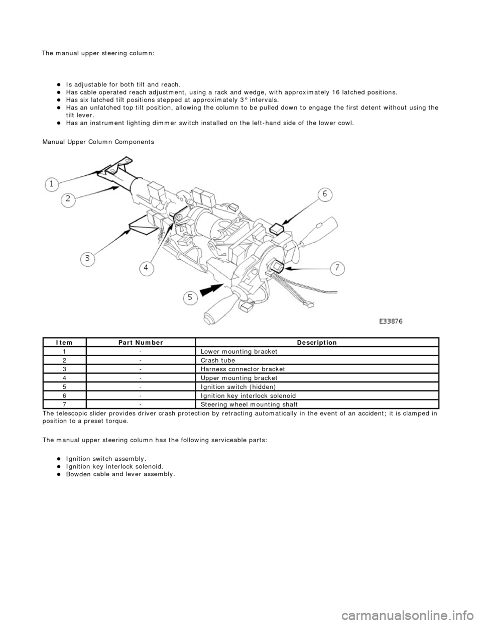
пЃ¬Is adjustable for both til
t and reach.
пЃ¬Has ca
ble operated reach adjustment, using a rack an
d wedge, with approximately 16 latched positions.
пЃ¬Has si
x latched tilt positions steppe
d at approximately 3В° intervals.
пЃ¬Has an u
nlatched top tilt position, allowing the column to be
pulled down to engage the first detent without using the
tilt lever.
пЃ¬Has an instrument li
ghti
ng dimmer switch installed on the left-hand side of the lower cowl.
Manual Upper Column Components
The telescopic slider provides driver crash protection by retracting automatically in the event of an accident; it is clamped in
position to a preset torque.
The manual upper steering column has the following serviceable parts:
пЃ¬Igni
tion switch assembly.
пЃ¬Igni
tion key interlock solenoid.
пЃ¬Bowden
cable and lever assembly.
It
em
Par
t Number
De
scription
1-L
ower mounting bracket
2-Crash tube
3-Harnes
s connector bracket
4-Upper
mounting bracket
5-Ignition switc
h (hidden)
6-Igni
tion key interlock solenoid
7-S
teering wheel mounting shaft
The manu
al upper
steering column:
Page 516 of 2490
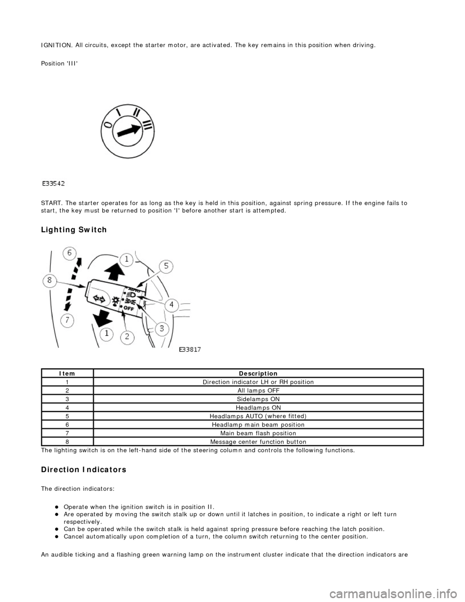
IGNITION.
All circuits, except the star
ter motor, are activated. The key rema ins in this position when driving.
Position 'III'
START. The starter operates for as long as the key is held in this position, ag ainst spring pressure. If the engine fails to
start, the key must be returned to position 'I' befo re another start is attempted.
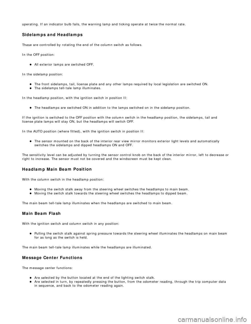
Lighting Switch
The li
ghting switch is on the left-h
and side of the steering column and controls the following functions.
Direction Indicators
The direction in
dicators:
пЃ¬Operate
when the ignition switch is in position II.
пЃ¬Are operat
ed by movi
ng the switch stalk up or down until it latches in position, to in
dicate a right or left turn
respectively.
пЃ¬Can be o p
erated while the switch stalk is held against
spring pressure before reaching the latch position.
пЃ¬Cancel
automatically upon completion of a turn, the
column switch returning to the center position.
An audible ticking and a flashing green warning lamp on the in strument cluster indicate that the direction indicators are
Ite
m
De
scr
iption
1D
i
rection indicator LH or RH position
2All lamps OFF
3Side
lamps ON
4Headlamps ON
5Headlamps AUT O
(where fitted)
6He
adlam
p main beam position
7Mai
n
beam flash position
8M
e
ssage center function button
Page 517 of 2490
o
perating. If an indicator bulb fails, the warning
lamp and ticking operate at twice the normal rate.
Sidelam
ps and Headlamps
Thes
e are controlled by rotating the end of the column switch as follows.
In the OFF position:
пЃ¬All
exterior lamps are switched OFF.
In the sidelamp position:
пЃ¬The front
sidelamps, tail, license plate and any other la
mps required by local legislation are switched ON.
пЃ¬The
sidelamps tell-tale lamp illuminates.
In the headlamp position, with the ignition switch in position II:
пЃ¬The h
eadlamps are switched ON in addition to the lamps switched on in the sidelamp position.
If the ignition is switched to the OFF position with the column switch in the headlamp position, the sidelamps, tail and
license plate lamps will stay ON, but the headlamps will switch OFF.
In the AUTO position (where fitted), with the ignition switch in position II:
пЃ¬Th
e sensor mounted on the back of the interior rear view
mirror monitors exterior light levels and automatically
switches the sidelamps and di pped headlamps ON and OFF.
The sensitivity level can be adjusted by turn ing the sensor control knob on the back of the interior mirror, left to decrease or
right to increase. The sensor must not be covered and the windscreen must be kept clean.
Headlamp Main Bea
m Position
Wi
th the column switch in
the headlamp position:
пЃ¬Movin
g the switch stalk away fro
m the steering wheel switches the headlamps to main beam.
пЃ¬Movin
g the switch stalk towards the steering wheel switches the headlamps to dipped beam.
The main beam tell-tale lamp illuminates when the headlamps are switched to main beam.
Ma
in Beam Flash
Wi
th the ignition switch and column switch in any position:
пЃ¬Pulling the
switch stalk agains
t spring pressure towards th e steering wheel illuminates the headlamps on main beam
for as long as the switch is held.
The main beam tell-tale lamp illuminates while the headlamps are illuminated.
M
essage Center Functions
T
he message center functions:
пЃ¬Are se
lected by the button located at the end of the lighting switch stalk.
пЃ¬Are se
lected in turn, by repeatedly pressing the button,
from the odometer reading, through the trip computer data
in sequence, and back to th e odometer reading again.
Page 522 of 2490
diverter val
ve (if fitted) and oil filter.
пЃ¬Main
bearings
which are grooved in the upper positions and plain in
the lower positions. They are manufactured from
aluminium / tin material.
пЃ¬A c
rankshaft with under
cuts and rolled fillets for extra strength.
пЃ¬Fracture
-split connecting rods in sintered-forged steel.
пЃ¬Brackets
bolted to the front of
the cylinder
block are used to mo unt all accessories.
пЃ¬A sin
gle, seven ribbed vee belt
drives the accessories.
пЃ¬An au
tomatic belt tensioner for the front accessory drive,
incorporating a wear indicator.
пЃ¬An advanced en
gine management system inco
rporating electronic throttle control.
пЃ¬The un
it meets the requirements of the CARB OBDII USA legislation.
Ancillary Systems
The an
ci
llary systems, driven by the engine, each have a
detailed Description and Operation along with Diagnostic
Procedures, and Removal and Installation instructions ; refer to the following sections of this manual:
пЃ¬Power Steeri
ng Pump - Section 211-02
пЃ¬Ai
r Conditioning Compressor - Sectio
n 412-03
пЃ¬Engine
C
ooling Pump - Section 303-03
пЃ¬Generator
- Sectio
n 414-02
The drive belt, idler pulley and automatic tensioner are described in Section 303-05.
The engine starting system is described in Section 303-06.
En
gine Management and Emission Control System
Engine Control Modu
le (ECM)
Engine
management and exhaust emissions are controlled by the ECM, which has the
following main functions:
пЃ¬Fu
el injection
пЃ¬Idle
s
peed
пЃ¬Ignition пЃ¬Ev
aporative loss system
пЃ¬Engine
cooling fans пЃ¬Clim
ate control compressor clutch demand
The microprocessor within the ECM receiv es signals from various sensors and other modules and uses a pre-determined
program to compute engine management functions.
Adaptive functions are incorporated in the ECM to cater for co ntinuous adjustments to its computations to suit prevailing
conditions. Because the system also controls emissions to suit all modes, neither CO levels nor idle speed require service
attention or adjustment, except if an error should occur.
On Board Diagnostics are controlled by the ECM with the continuous monitoring of incoming signals and the subsequent
verification against what the module expects to 'see'. Should a si gnal be incorrect or missing, the ECM will substitute a fixed
value to provide the 'limp home mode' and alert the driver of the problem. Fixed values may be adopted for:
пЃ¬Transmission oil
temperature
пЃ¬Mechanica
l
guar
d position
пЃ¬Throttle blade angle пЃ¬Camshaft position
пЃ¬Inta
k
e air temperature
Diagnostic trouble codes (DTC), including OBD II codes, are stored in the ECM memo ry and can be read by an appropriate
retrieval tool.
Should either the ECM or TCM fa il, ensure that the control housing cooling fan is operating correctly. Failure of the cooling
fan MUST be rectified before renewing a control module and details of a fa n failure should accompany a returned control
module.
Page 617 of 2490
Inst
allation
пЃ¬Cl
ean the gasket faces of the catalyst and the exhaust manifold.
38. Clean cylinder head and cylinder block gasket faces.
пЃ¬E
nsure that all threaded holes in the cylinder block face are clean and
free from oil.
пЃ¬Cl
ean and inspect the cylinder head bolts. They may be re-used on two
occasions. When re- used, each bolt head should be marked with one
dot from an automatic centre punch.
39. Clean and inspect all relevant components and mating faces.
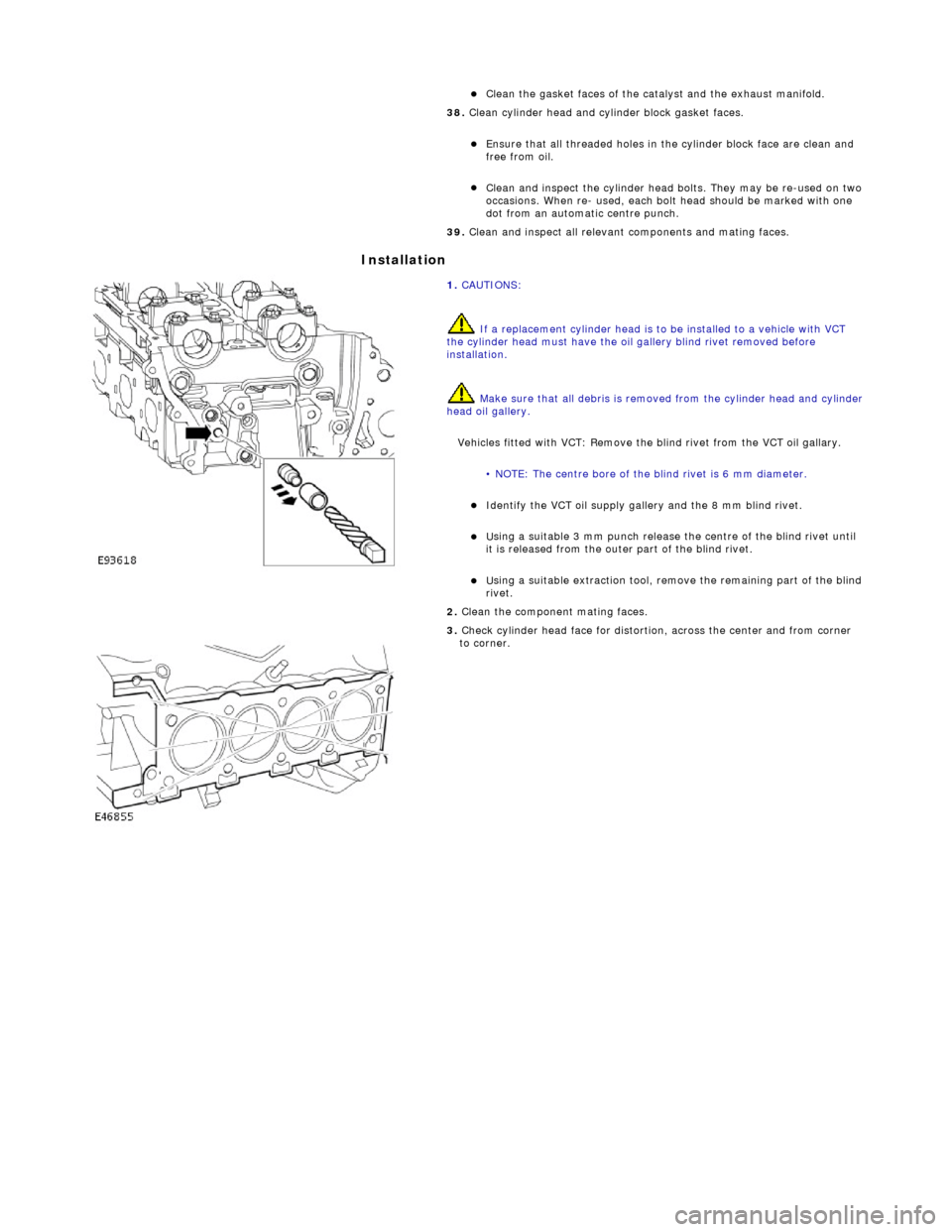
1.
CAUTIONS:
If a replacement cylinder head is to be installed to a vehicle with VCT
the cylinder head must have the oil gallery blind rivet removed before
installation.
Make sure that all debris is removed from the cylinder head and cylinder
head oil gallery.
Vehicles fitted with VCT: Remove the blind rivet from the VCT oil gallary.
• NOTE: The centre bore of the blind rivet is 6 mm diameter.
пЃ¬I
dentify the VCT oil supply gallery and the 8 mm blind rivet.
пЃ¬U
sing a suitable 3 mm punch release the centre of the blind rivet until
it is released from the outer part of the blind rivet.
пЃ¬U
sing a suitable extraction tool, remo
ve the remaining part of the blind
rivet.
2.
Clean the component mating faces.
3.
Check cylinder head face for distortio
n, across the center and from corner
to corner.
Page 632 of 2490

Installation
hea
d.
3. With assistance, remove the cylinder head.
34 . R
emove the cylinder head gasket.
1. Note how the gasket is installed and remove it.
2. Remove and discard the cloth, placed previously to absorb coolant spillage.
пЃ¬Wipe up any l e
aked coolant.
35. Remove the coolant drain tray from under the engine.
36. Remove and discard the gasket from the downpipe catalyst.
пЃ¬Cle
an the gasket faces of the catalyst and the exhaust manifold.
37. Clean cylinder head and cylinder block gasket faces.
пЃ¬Ensu
re that all threaded holes in the cylinder block face are clean and
free from oil.
пЃ¬Cl ean and
inspect the cylinder head bolts. They may be re-used on two
occasions. When re- used, each bolt head should be marked with one
dot from an automatic centre punch.
38. Clean and inspect all relevant components and mating faces.
1. CAUTIONS: If a replacement cylinder head is to be installed to a vehicle with VCT
the cylinder head must have the oil gallery blind rivet removed before
installation.
Make sure that all debris is removed from the cylinder head and cylinder
head oil gallery.
Vehicles fitted with VCT: Remove the blind rivet from the VCT oil gallary. • NOTE: The centre bore of the blind rivet is 6 mm diameter.