AUTOMATIC JAGUAR X308 1998 2.G Owner's Manual
[x] Cancel search | Manufacturer: JAGUAR, Model Year: 1998, Model line: X308, Model: JAGUAR X308 1998 2.GPages: 2490, PDF Size: 69.81 MB
Page 923 of 2490
be 'hun
g up' within the engine because it is not up to operating
temperature.
Should the oil level subsequently be topped-up, the level could
become too high, causing oil burning.
Typically, 0.875L is hung up.
Refill the engine with the correct specification engine oil.
58. Refill the automatic transmission. Refer to Section 307-01A,
Operation 44.24. 02.
59. Refill and bleed the power stee ring system. Refer to Section
211-02 General Procedures.
60. Repressurise the air conditioni ng system. Refer to Operation
82.30.30 and note all Wa rnings and Cautions.
61
.
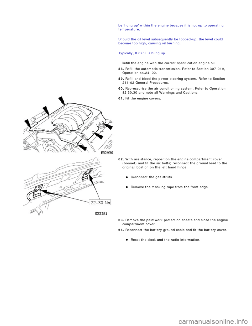
Fit the engine covers.
62
.
With assistance, reposition the engine compartment cover
(bonnet) and fit the si x bolts; reconnect the ground lead to the
original location on the left hand hinge.
пЃ¬Re
connect the gas struts.
пЃ¬R
emove the masking tape from the front edge.
63. Remove the paintwork protection sheets and close the engine
compartment cover.
64. Reconnect the battery ground cable and fit the battery cover.
пЃ¬Re
set the clock and the radio information.
Page 931 of 2490
s
ystem (pressure).
Outputs from the ECM control the radiator fans control module, located behind the left hand side of the bumper, to operate
the fans in the series mode (slow), paralle l mode (Fast) or Off modes. Hysteresis in the temperature and pressure switching
values prevents 'hun ting' between modes.
Under hot operating conditions, the fans may continue to operat e for some time after the engine has been switched off, but
will stop automatically when the coolant te mperature has been sufficiently reduced.
Engine Coolant Temperature Sensor (ECT) and ECM
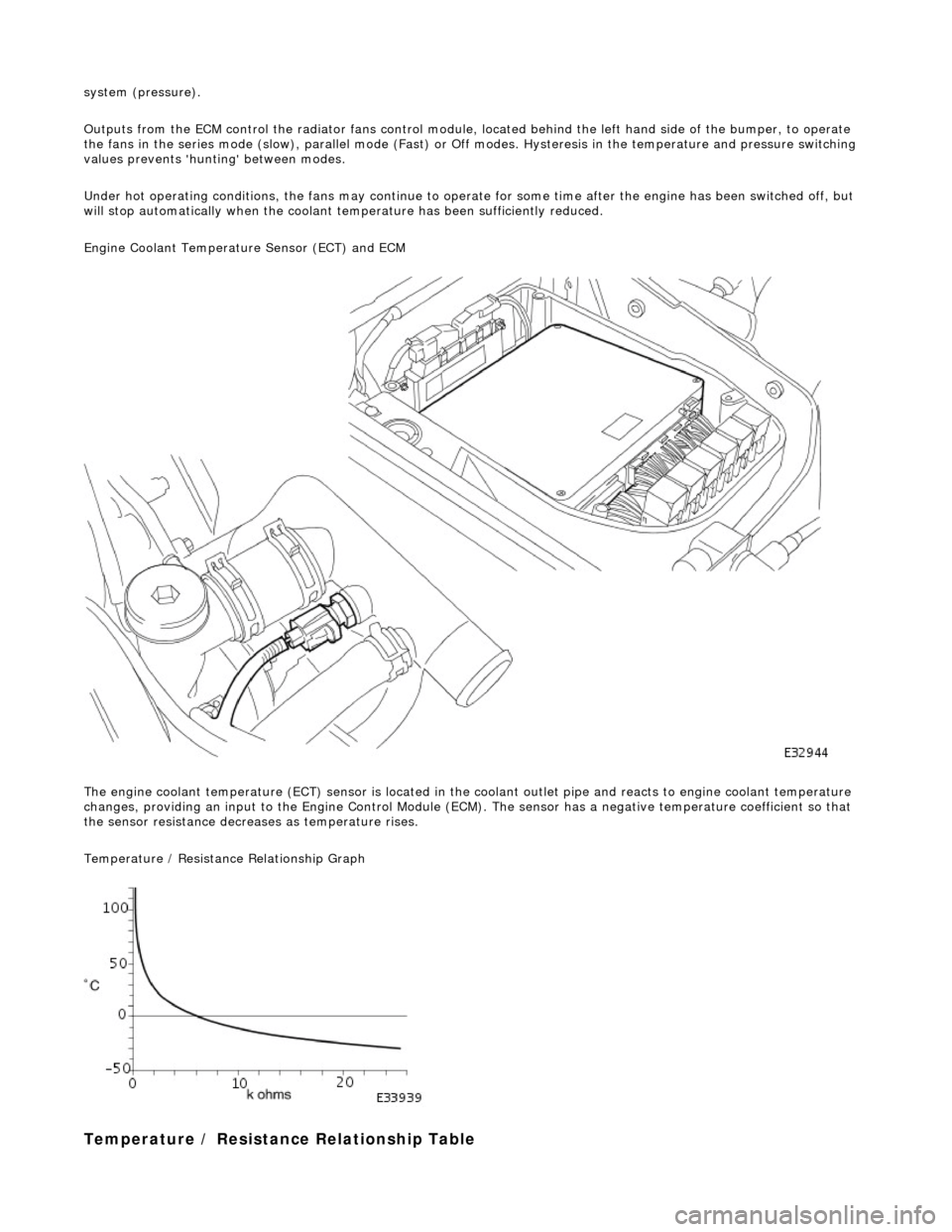
The engine coolant temperature (ECT) sensor is located in the coolant outlet pipe and reacts to engine coolant temperature
changes, providing an input to the Engine Control Module (ECM). The sensor has a negative te mperature coefficient so that
the sensor resistance decrea ses as temperature rises.
Temperature / Resistance Relationship Graph
T
emperature / Resistance
Relationship Table
Page 977 of 2490
conde
nser.
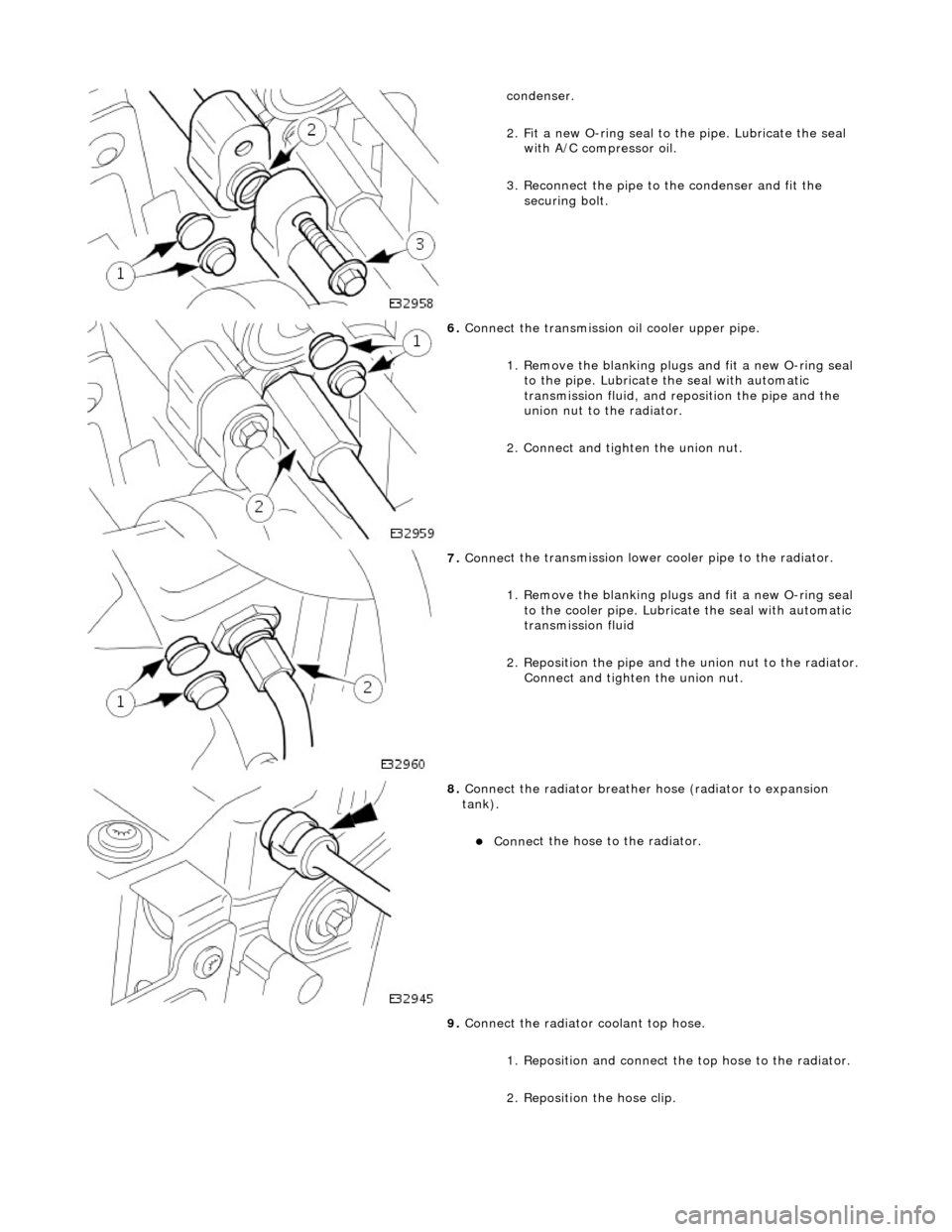
2. Fit a new O-ring seal to the pipe. Lubricate the seal with A/C compressor oil.
3. Reconnect the pipe to the condenser and fit the securing bolt.
6. Conne
ct the transmission
oil cooler upper pipe.
1. Remove the blanking plugs and fit a new O-ring seal to the pipe. Lubricate the seal with automatic
transmission fluid, and re position the pipe and the
union nut to the radiator.
2. Connect and tighten the union nut.
7. Conne
ct the transmission lower cooler pipe to the radiator.
1. Remove the blanking plugs and fit a new O-ring seal to the cooler pipe. Lubricate the seal with automatic
transmission fluid
2. Reposition the pipe and th e union nut to the radiator.
Connect and tighten the union nut.
8. Connect
the radiator breather
hose (radiator to expansion
tank).
пЃ¬Conne
ct the hose to the radiator.
9. Connect the radiator coolant top hose.
1. Reposition and connect the top hose to the radiator.
2. Reposition the hose clip.
Page 984 of 2490

conden
ser.
2. Fit a new O-ring seal to the pipe. Lubricate the seal with A/C compressor oil.
3. Reconnect the pipe to the condenser and fit the securing bolt.
6. Conne ct
the transmission
oil cooler upper pipe.
1. Remove the blanking plugs and fit a new O-ring seal to the pipe. Lubricate the seal with automatic
transmission fluid, and re position the pipe and the
union nut to the radiator.
2. Connect and tighten the union nut.
7. Conne ct
the transmission lower cooler pipe to the radiator.
1. Remove the blanking plugs and fit a new O-ring seal to the cooler pipe. Lubricate the seal with automatic
transmission fluid
2. Reposition the pipe and th e union nut to the radiator.
Connect and tighten the union nut.
8. Connect the radiator br
eather
hose (radiator to expansion
tank).
пЃ¬Conne ct
the hose to the radiator.
9. Connect the radiator coolant top hose.
1. Reposition and connect the top hose to the radiator.
2. Reposition the hose clip.
Page 1051 of 2490

The
automatic belt tensioner consists of an idler pulley which is
free to rotate on a bearing, located at the end of a spring-
loaded pivot arm.
The pivot arm can be turned counter-clockwise (viewed from th e front of the engine) for belt removal and installation.
A belt-wear indicator is incorporated on th e rear horizontal face of the pivot arm.
It
em
De
scription
1Bel
t Wear Indicator
2Re
new Belt Indicator
3N
ew Belt Maximum Length
4N
ew Belt Minimum Length
Au
tomatic Belt Tensioner
Page 1260 of 2490
Automatic Transmission/Transaxle - 4.0L NA V8 - AJ27/3.2L NA V8 - AJ26
-
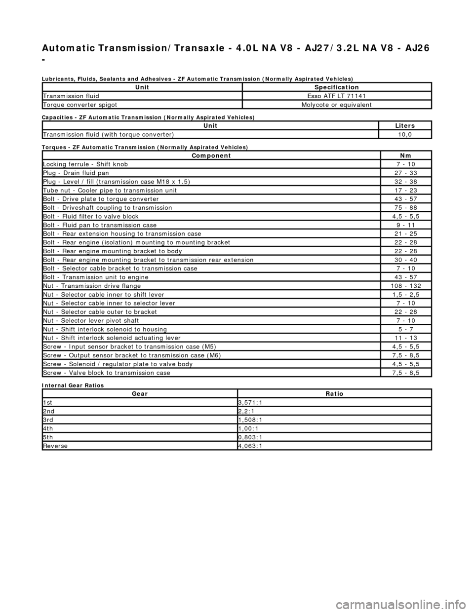
Lubri c
ants, Fluids, Sealants and Adhesives - ZF Au
tomatic Transmission (Normally Aspirated Vehicles)
Capacities - ZF Automatic Transmission (Normally Aspirated Vehicles)
Torques - ZF Automatic Transmission (Normally Aspirated Vehicles)
Internal Gear Ratios
UnitS p
ecification
Transmissi
on fluidEsso
ATF LT 71141
Torque converter spigotMolyc
o
te or equivalent
UnitLi
t
ers
Transmissi
on fluid (with
torque converter)
10
,0
Com p
onent
Nm
Locki
n
g ferrule - Shift knob
7 -
10
P
l
ug - Drain fluid pan
27
-
33
P
l
ug - Level / fill (transmission case M18 x 1.5)
32
-
38
Tu
be
nut - Cooler pipe to transmission unit
17
-
23
B
o
lt - Drive plate to torque converter
43
-
57
B
o
lt - Driveshaft coupling to transmission
75
-
88
Bo
lt
- Fluid filter to valve block
4,
5 -
5,5
Bolt
-
Fluid pan to transmission case
9 -
11
B
o
lt - Rear extension housing to transmission case
21
-
25
Bolt
-
Rear engine (isolation) mounting to mounting bracket
22
-
28
Bolt -
Rear engine moun
ting bracket to body
22
-
28
Bolt
-
Rear engine mounting bracke
t to transmission rear extension
30 -
40
B
o
lt - Selector cable bracket to transmission case
7 -
10
Bolt
-
Transmission unit to engine
43
-
57
Nu
t -
Transmission drive flange
1
08 -
132
Nu
t -
Selector cable inner to shift lever
1,
5 -
2,5
Nu
t -
Selector cable inner to selector lever
7 -
10
Nu
t -
Selector cable outer to bracket
22
-
28
Nu
t
- Selector lever pivot shaft
7 -
10
Nu
t -
Shift interlock solenoid to housing
5 -
7
Nut -
Shift interlock solenoid actuating lever
11
-
13
Sc
re
w - Input sensor bracket to transmission case (M5)
4,
5 -
5,5
Screw
-
Output sensor bracket to transmission case (M6)
7,
5 -
8,5
Screw
-
Solenoid / regulator plate to valve body
4,
5 -
5,5
Sc
re
w - Valve block to transmission case
7,
5 -
8,5
GearRatio
1s
t3,57
1:1
2n
d2,2:
1
3r
d1,50
8:1
4t
h1,00
:1
5t
h0,80
3:1
Re
ve
rse
4,
06
3:1
Page 1261 of 2490
Automatic Transmission/Transaxle - 4.0L NA V8 - AJ27/3.2L NA V8 - AJ26
- Transmission Descriptio
n
Description an
d Operation
Transmission As
sembly
Int
roduction
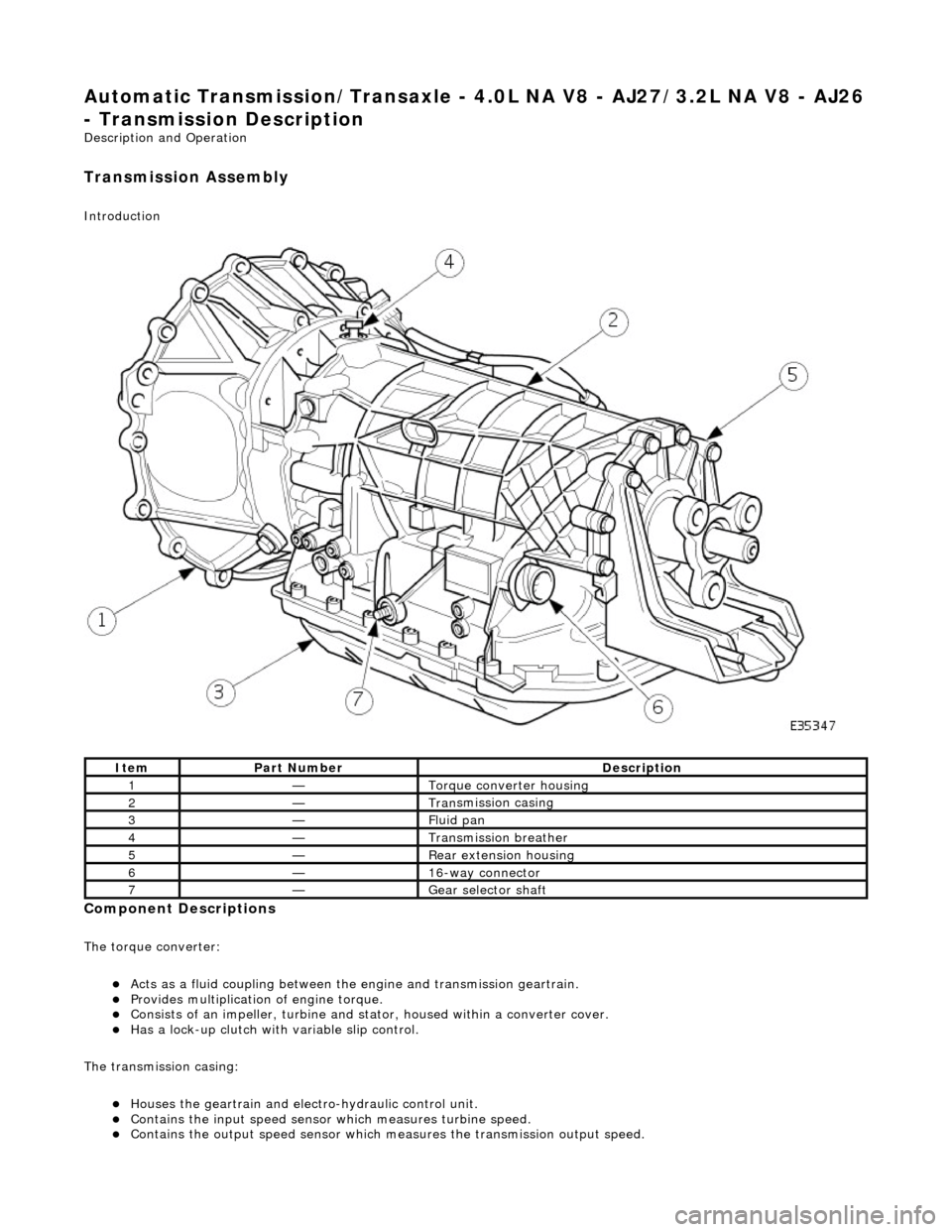
Compon
ent Descriptions
The t
orque converter:
пЃ¬Acts as a fluid
coupling between the
engine and transmission geartrain.
пЃ¬P
rovides multiplication of engine torque.
пЃ¬Cons
ists of an impeller, turbine and stat
or, housed within a converter cover.
пЃ¬Has a l
ock-up clutch with variable slip control.
The transmission casing:
пЃ¬Houses the geartrain and elec t
ro-hydraulic control unit.
пЃ¬Contains
the input speed sensor which measures turbine speed.
пЃ¬Contai
ns the output speed sensor which measures the transmission output speed.
It
em
Par
t Number
De
scription
1—Torque c
onverter housing
2—Tran
smission casing
3—Fluid pan
4—Transmission bre
ather
5—Re
ar extension housing
6—16
-way connector
7—Gear s
elector shaft
Page 1275 of 2490
Automatic Transmission/Transaxle - 4.0L NA V8 - AJ27/3.2L NA V8 - AJ26
- Diagnostic Strategy
Diagnosis and Testing
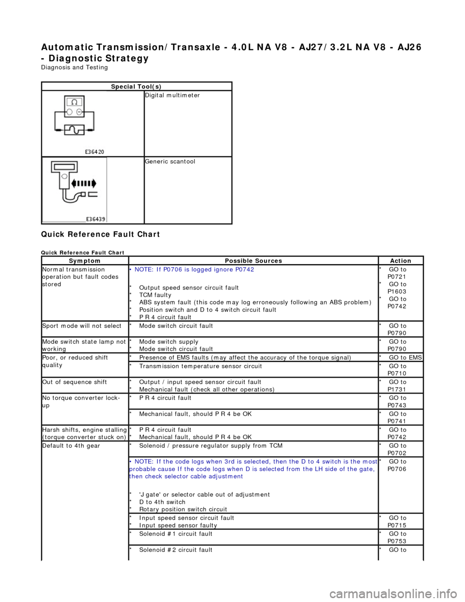
Quick Reference Fault Chart
Quick Reference Fault Chart
Special Tool(s)
Digital multimeter
Generic scantool
SymptomPossible SourcesAction
Normal transmission
operation but fault codes
stored• NOTE: If P0706 is logged ignore P0742
Output speed sensor circuit fault
TCM faulty
ABS system fault (this code may log er roneously following an ABS problem)
Position switch and D to 4 switch circuit fault
P R 4 circuit fault
*
*
*
*
*
GO to
P0721 GO to
P1603 GO to
P0742
*
*
*
Sport mode will not selectMode switch circuit fault
*GO to
P0790
*
Mode switch state lamp not
workingMode switch supply
Mode switch circuit fault
*
*GO to
P0790
*
Poor, or reduced shift
qualityPresence of EMS faults
(may affect the accuracy of the torque signal)
*GO to EMS *
Transmission temperature sensor circuit
*GO to
P0710
*
Out of sequence shiftOutput / input speed sensor circuit fault
Mechanical fault (check all other operations)
*
*GO to
P1731
*
No torque converter lock-
upP R 4 circuit fault
*GO to
P0743
*
Mechanical fault, should P R 4 be OK
*GO to
P0741
*
Harsh shifts, engine stalling (torque converter stuck on)P R 4 circuit fault
Mechanical fault, should P R 4 be OK
*
*GO to
P0742
*
Default to 4th gearSolenoid / pressure regulator supply from TCM
*GO to
P0702
*
• NOTE: If the code logs wh
en 3rd is selected, then the D to 4 switch is the most probable cause If the code logs when D is selected fro m the LH side of the gate,
then check selector cable adjustment
'J gate' or selector ca ble out of adjustment
D to 4th switch
Rotary position switch circuit
*
*
*GO to
P0706
*
Input speed sensor circuit fault
Input speed sensor faulty
*
*GO to
P0715
*
Solenoid #1 circuit fault
*GO to
P0753
*
Solenoid #2 circuit fault
*GO to
*
Page 1335 of 2490
Automatic Transmission/Transaxle - 4.0L NA V8 - AJ27/3.2L NA V8 - AJ26
- Transmission Fluid Drain and Refill
General Procedures
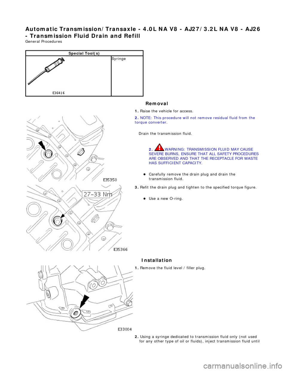
Removal
Installation
Special Tool(s)
Syringe 1. Raise the vehicle for access.
2. NOTE: This procedure will not re move residual fluid from the
torque converter.
Drain the transmission fluid.
2. WARNING: TRANSMISSION FLUID MAY CAUSE
SEVERE BURNS, ENSURE THAT ALL SAFETY PROCEDURES
ARE OBSERVED AND THAT THE RECEPTACLE FOR WASTE
HAS SUFFICIENT CAPACITY.
пЃ¬Carefully remove the drain plug and drain the
transmission fluid.
3. Refit the drain plug and tighten to the specified torque figure.
пЃ¬Use a new O-ring.
1. Remove the fluid level / filler plug.
2. Using a syringe dedicated to tran smission fluid only (not used
for any other type of oil or fluids ), inject transmission fluid until
Page 1339 of 2490

Automatic Transmission/Transaxle - 4.0L NA V8 - AJ27/3.2L NA V8 - AJ26
- Electronic Pressure Control (EPC) Solenoid
In-vehicle Repair
Removal
1. Disconnect battery ground cable.
пЃ¬Remove the battery cover.
2. Raise the vehicle on a suitable lift.
2. WARNING: TRANSMISSION FLUID MAY CAUSE
SEVERE BURNS, ENSURE THAT ALL SAFETY PROCEDURES
ARE OBSERVED.
пЃ¬Carefully remove the drain plug and drain the
transmission fluid.
3. Remove the twenty-two fixings which secure the fluid pan .
пЃ¬Remove the fluid pan and all traces of gasket material.
4. Disconnect regulator / solenoid connectors.
5. Remove RH rear valve body securing screws.