B pillar JAGUAR X308 1998 2.G User Guide
[x] Cancel search | Manufacturer: JAGUAR, Model Year: 1998, Model line: X308, Model: JAGUAR X308 1998 2.GPages: 2490, PDF Size: 69.81 MB
Page 2060 of 2490

Installation
1. To install, reverse the removal procedure.
пЃ¬Fit new fir tree fasteners to the C-pillar trim panel.
Page 2076 of 2490

Interior Trim and Ornamentation - Headliner
Removal and Installation
Removal
Vehicles with roof opening panel
All vehicles
1. Remove the roof opening panel trim.
For additional information, refer to: Roof Opening Panel Trim
(501-17 Roof Opening Panel, Removal and Installation).
2. Remove both C-pill ar trim panels.
For additional information, refer to: C
-Pillar Trim Panel (501-05
Interior Trim and Ornamentatio n, Removal and Installation).
3. Remove both A-pill ar trim panels.
For additional information, refer to: A
-Pillar Trim Panel (501-05
Interior Trim and Ornamentatio n, Removal and Installation).
4. Remove the overhead console.
For additional information, refer to: Overhead Console
(501-12
Instrument Panel and Console, Removal and Installation).
5. Remove the rear window glass.
For additional information, refer to: Rear Window Glass
(501-
11 Glass, Frames and Mechanis ms, Removal and Installation).
6. Disconnect the anti-theft se nsors electrical connector.
7. CAUTION: With the aid of an other technician, support the
headliner to ensure it is not folded or creased during removal.
Remove both sun visors.
For additional information, refer to: Sun Visor
(501-05 Interior
Trim and Ornamentation, Re moval and Installation).
8. NOTE: Left-hand shown, right-hand similar.
Detach the retaining screw cove r from the headliner retaining
trim.
9. NOTE: Left-hand shown, right-hand similar.
Remove the headline r retaining trim.
Page 2079 of 2490

Vehicles with roof opening panel
7. Install both sun visors.
For additional information, refer to: Sun Visor (501-05 Interior
Trim and Ornamentation, Re moval and Installation).
8. Install the rear window glass.
For additional information, refer to: Rear Window Glass
(501-
11 Glass, Frames and Mechanis ms, Removal and Installation).
9. Fit the electrical connectors into the retaining clips at the
overhead console location.
10. Install the overhead console.
For additional information, refer to: Overhead Console
(501-12
Instrument Panel and Console, Removal and Installation).
11. Install both C-pillar trim panels.
For additional information, refer to: C
-Pillar Trim Panel (501-05
Interior Trim and Ornamentatio n, Removal and Installation).
12. Install both A-pillar trim panels.
For additional information, refer to: A
-Pillar Trim Panel (501-05
Interior Trim and Ornamentatio n, Removal and Installation).
13. Install the roof opening panel trim.
For additional information, refer to: Roof Opening Panel Trim
(501-17 Roof Opening Panel, Removal and Installation).
Page 2100 of 2490

Exterior Trim and Ornamentation - A-Pillar Moulding LH
Removal and Installation
Removal
Installation
1.
Remove front and rear grab handles. Refer to 76.58.30
2. Remove draught welt from adjace nt section of door aperture
flange.
3. Using a trim removal tool, carefu lly ease the six trim pad fir
tree fasteners from cantrail an d upper'A' post locations.
4. If premium ICE is fitt ed, carefully withdraw trim pad for access
and disconnect tweeter connectors.
5. Remove trim pad from vehicle an d remove tweeter. Refer to
415-03.
6. Remove and discard fir tree fasteners.
1. Fit new fir tree fasten ers to the trim pad.
2. Fit tweeter to trim pad. Refer to Section 415.
3. Position trim pad for access and connect tweeter to harness.
4. Commencing at top of 'A' post and working rearwards, fully
seat three fir tree fasteners.
5. Fully seat remaining three fir tr ee fasteners in upper'A' post.
6. Fit front and rear combined gr ab handles. Refer to 76.58.30
7. Fit draught welt to adjacent section of door aperture flange.
Page 2101 of 2490

Exterior Trim and Ornamentation - A-Pillar Moulding RH
Removal and Installation
Removal
Installation
1.
Remove rear grab handle. Refer to 76.58.30.
2. Remove draught welt from adjace nt section of door aperture
flange.
3. Using a trim removal tool, carefu lly ease the six trim pad fir
tree fasteners from cantrail an d upper'A' post locations.
4. If premium ICE is fitt ed, carefully withdraw trim pad for access
and disconnect tweeter connectors.
5. Remove trim pad from vehicle an d remove tweeter. Refer to
415-03.
6. Remove and discard fir tree fasteners.
1. Fit new fir tree fasten ers to the trim pad.
2. Fit tweeter to trim pad. Refer to Section 415.
3. Position trim pad for access and connect tweeter to harness.
4. Commencing at top of 'A' post and working rearwards, fully
seat three fir tree fasteners.
5. Fully seat remaining three fir tr ee fasteners in upper'A' post.
6. Fit grab handle. Refer to 76.58.30.
7. Fit draught welt to adjacent section of door aperture flange.
Page 2200 of 2490
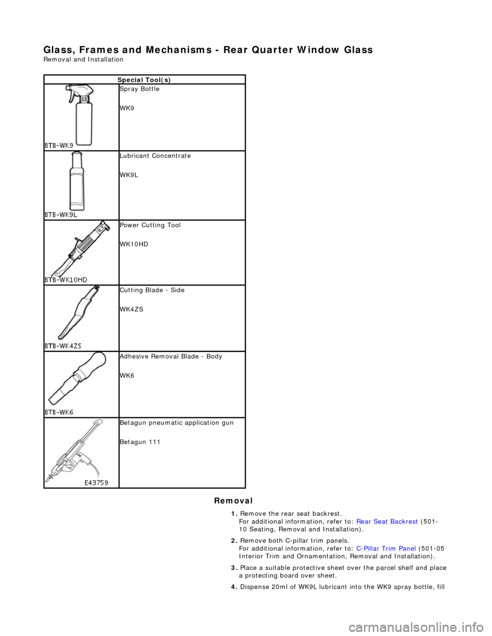
Glass, Frames and Mechanisms - Rear Quarter Window Glass
Removal and Installation
Removal
Special Tool(s)
Spray Bottle
WK9
Lubricant Concentrate
WK9L
Power Cutting Tool
WK10HD
Cutting Blade - Side
WK4ZS
Adhesive Removal Blade - Body
WK6
Betagun pneumatic application gun
Betagun 111
1. Remove the rear seat backrest.
For additional information, refer to: Rear Seat Backrest
(501-
10 Seating, Removal and Installation).
2. Remove both C-pill ar trim panels.
For additional information, refer to: C
-Pillar Trim Panel (501-05
Interior Trim and Ornamentatio n, Removal and Installation).
3. Place a suitable protective sheet over the parcel shelf and place
a protecting boar d over sheet.
4. Dispense 20ml of WK9L lubricant into the WK9 spray bottle, fill
Page 2203 of 2490
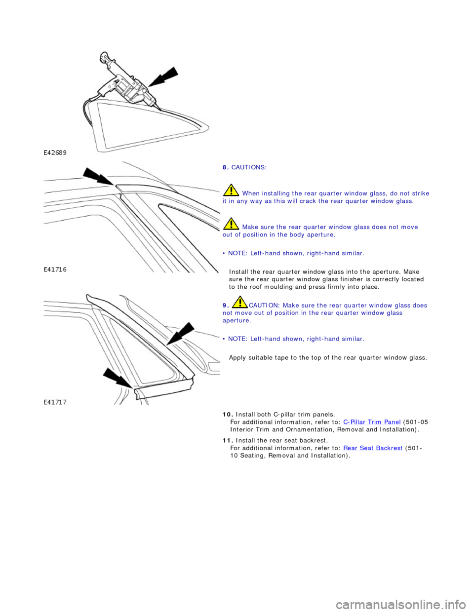
8. CAUTIONS:
When installing the rear quarte r window glass, do not strike it in any way as this will crack the rear quarter window glass.
Make sure the rear quarter window glass does not move
out of position in the body aperture.
• NOTE: Left-hand shown, right-hand similar.
Install the rear quar ter window glass into the aperture. Make
sure the rear quarter window glas s finisher is correctly located
to the roof moulding and press firmly into place.
9. CAUTION: Make sure the rear quarter window glass does
not move out of position in the rear quarter window glass
aperture.
• NOTE: Left-hand shown, right-hand similar.
Apply suitable tape to the top of the rear quarter window glass.
10. Install both C-pillar trim panels.
For additional information, refer to: C-Pillar Trim Panel (501-05
Interior Trim and Ornamentatio n, Removal and Installation).
11. Install the rear seat backrest.
For additional information, refer to: Rear Seat Backrest
(501-
10 Seating, Removal and Installation).
Page 2205 of 2490
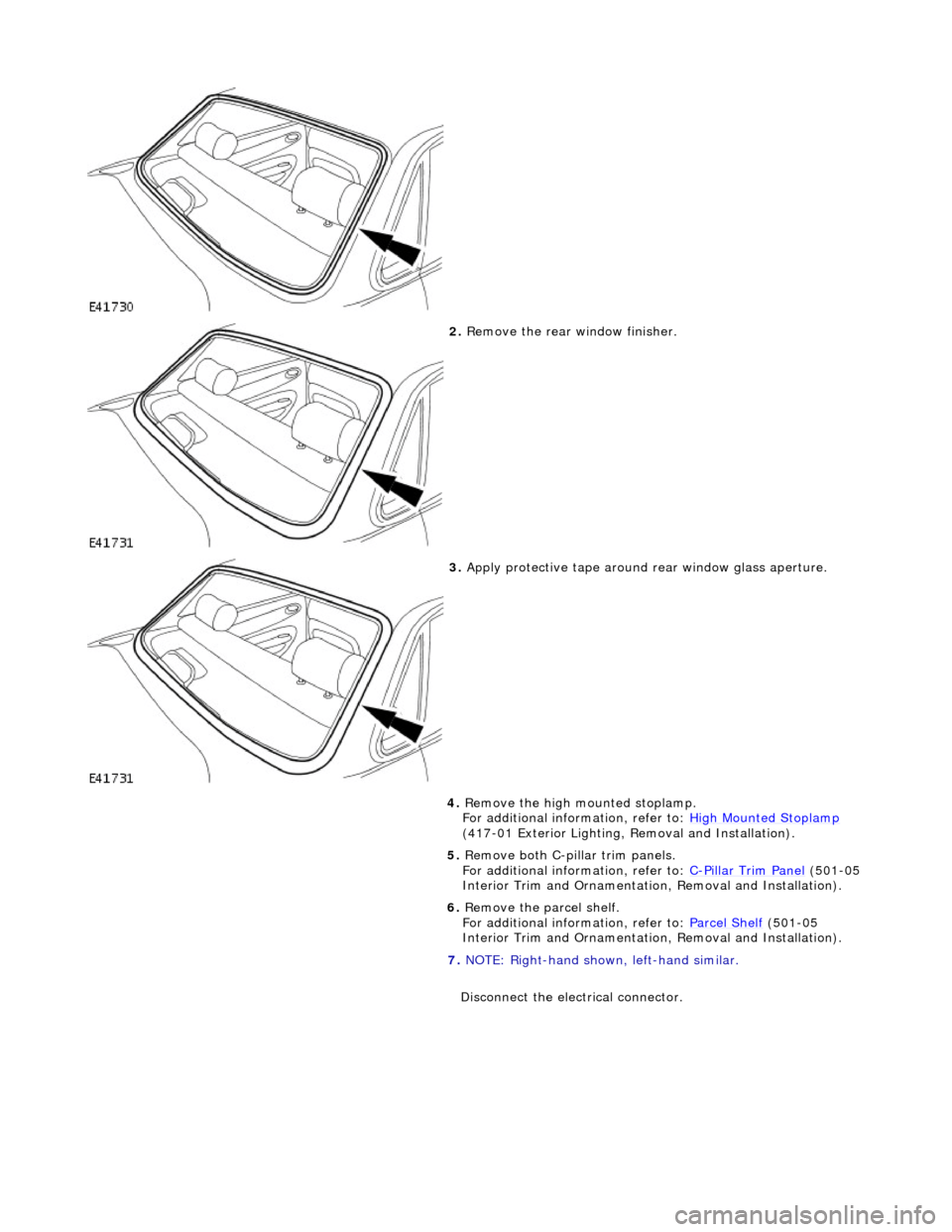
2. Remove the rear window finisher.
3. Apply protective tape around rear window glass aperture.
4. Remove the high mounted stoplamp.
For additional information, refer to: High Mounted Stoplamp
(417-01 Exterior Lighting, Removal and Installation).
5. Remove both C-pill ar trim panels.
For additional information, refer to: C
-Pillar Trim Panel (501-05
Interior Trim and Ornamentatio n, Removal and Installation).
6. Remove the parcel shelf.
For additional information, refer to: Parcel Shelf
(501-05
Interior Trim and Ornamentatio n, Removal and Installation).
7. NOTE: Right-hand shown, left-hand similar.
Disconnect the electrical connector.
Page 2206 of 2490
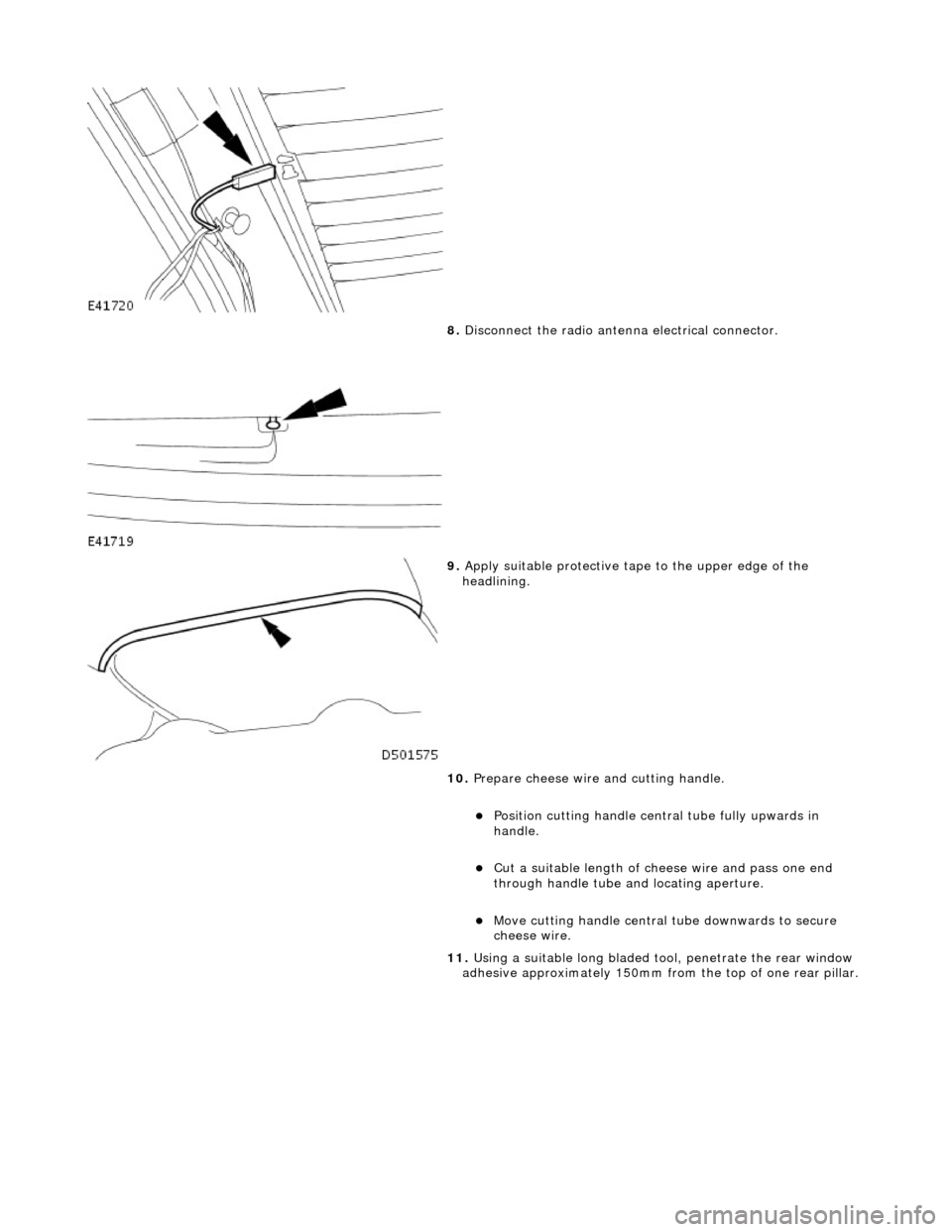
8. Disconnect the radio antenn a electrical connector.
9. Apply suitable protec tive tape to the upper edge of the
headlining.
10. Prepare cheese wire and cutting handle.
пЃ¬Position cutting handle cent ral tube fully upwards in
handle.
пЃ¬Cut a suitable length of ch eese wire and pass one end
through handle tube and locating aperture.
пЃ¬Move cutting handle central tube downwards to secure
cheese wire.
11. Using a suitable long bladed tool, penetrate the rear window
adhesive approximately 150mm fro m the top of one rear pillar.
Page 2210 of 2490
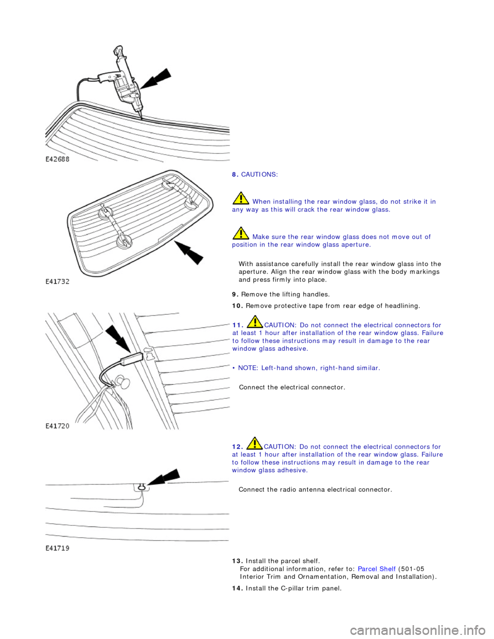
8. CAUTIONS:
When installing the rear window glass, do not strike it in
any way as this will crac k the rear window glass.
Make sure the rear window glass does not move out of
position in the rear window glass aperture.
With assistance carefully install the rear window glass into the
aperture. Align the rear window glass with the body markings
and press firmly into place.
9. Remove the lifting handles.
10. Remove protective tape from rear edge of headlining.
11. CAUTION: Do not connect the electrical connectors for
at least 1 hour after installation of the rear window glass. Failure
to follow these instructions may result in damage to the rear
window glass adhesive.
• NOTE: Left-hand shown, right-hand similar.
Connect the electrical connector.
12. CAUTION: Do not connect the electrical connectors for
at least 1 hour after installation of the rear window glass. Failure
to follow these instructions may result in damage to the rear
window glass adhesive.
Connect the radio antenna electrical connector.
13. Install the parcel shelf.
For additional information, refer to: Parcel Shelf (501-05
Interior Trim and Ornamentatio n, Removal and Installation).
14. Install the C-pillar trim panel.