body mounting JAGUAR X308 1998 2.G Workshop Manual
[x] Cancel search | Manufacturer: JAGUAR, Model Year: 1998, Model line: X308, Model: JAGUAR X308 1998 2.GPages: 2490, PDF Size: 69.81 MB
Page 34 of 2490

501‐20B : Supp l
emental
Restraint System
Specification
Description and Operation
Air Bag Supplemental Restraint System (SRS)
Removal and Installation
Air Bag Control Module (76.73.41)
Driver Air Bag Module (76.73.39)
Passenger Air Bag Module (76.73.37)
Side Air Bag Module (76.73.47)
Side Impact Sensor (76.73.53)
501‐25: Body Repairs ‐ Genera
l Information
Description and Operation
Body Repairs
502: Frame and Mounting
502‐00: Uni ‐Body, Subframe and Mounting System
Removal and Installation
Front Axle Crossmember
Front Axle Crossmember Front Bushing (60.35.24)
Front Axle Crossmember Front Bushing Heat Shield (60.35.37)
Front Axle Crossmember Rear Bushing (
60.35.26)
Rear Axle Crossmember (64.25.16)
Rear Axle Crossmember Bushing (64.25.02)
Page 67 of 2490
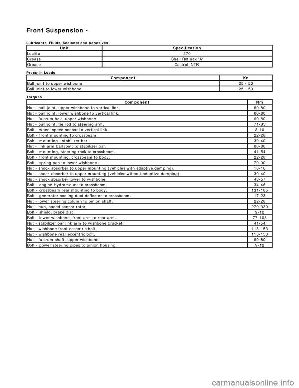
Front Suspension -
Lubri
cants, Fluids, Sealants and Adhesives
Press-In Loads
Torques
UnitS
pecification
Loctite27
0
Greas
e
Shell Retin
ax 'A'
Greas
e
Castro
l 'NTR'
Com
ponent
Kn
Ball join
t to upper wishbone
25
- 50
B
all joint to lower wishbone
25
- 50
Com
ponent
Nm
N
ut - ball joint, upper wishbone to vertical link.
60
-80
N
ut - ball joint, lower wishbone to vertical link.
60
-80
Nu
t - fulcrum bolt, upper wishbone.
60
-80
N
ut - ball joint, tie rod to steering arm.
71
-85
Bol
t - wheel speed sensor to vertical link.
8-1
0
Bol
t - front mounting to crossbeam.
22
-28
Bolt
- mounting , stabilizer bar.
30
-40
N
ut - link arm ball joint to stabilizer bar.
60
-80
Bolt
- mounting, steering rack to crossbeam.
41
-54
B
olt - front mounting, crossbeam to body.
22
-28
Bol
t - spring pan to lower wishbone.
70
-90
N
ut - shock absorber to upper mounting
(vehicles with adaptive damping).
16
-18
Nu
t - shock absorber to upper mounting (vehicles without adaptive damping).
30
-40
N
ut - shock absorber lower to wishbone.
43
-57
B
olt - engine Hydramount to crossbeam.
34
-46
B
olt - crossbeam rear mounting to body.
13
1-185
Bol
t - generator cooling du
ct deflector to crossbeam.
17
-23
N
ut - lower steering column to pinion shaft.
22
-28
N
ut - hub, speed sensor rotor.
27
0-330
B
olt - shield, brake disc.
9-1
2
Bol
t - lower wishbone, front arm to rear arm.
77
-103
Nu
t - stabilizer bar link arm to wishbone bracket.
41
-54
N
ut - wishbone front
eccentric bolt.
11
3-153
Nu
t - wishbone rear
eccentric bolt.
11
3-153
N
ut - fulcrum shaft, upper wishbone.
60
-80
Bolt -
power steering pi
pes to pinion housing.
9-1
2
Page 69 of 2490
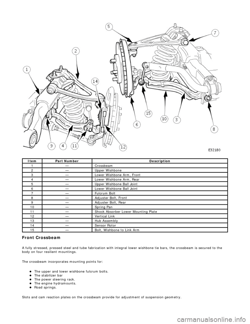
Front C
rossbeam
A
fully stressed, pressed steel and tube fa
brication with integral lower wishbone tie bars, the crossbeam is secured to the
body on four resilient mountings.
The crossbeam incorporates mounting points for:
The u
pper and lower wish
bone fulcrum bolts.
The
stabilizer bar
The power steering rack. The engine h
ydramounts.
R
oad springs.
Slots and cam reaction pl ates on the crossbeam provide for ad justment of suspension geometry.
It
em
Par
t Number
De
scription
1—Cro
ssbeam
2—Upper
Wishbone
3—Lower Wi
shbone Arm, Front
4—Lower Wi
shbone Arm, Rear
5—Upper
Wishbone Ball Joint
6—Lower Wi
shbone Ball Joint
7—Ful
crum Bolt
8—Adjuster B
olt, Front
9—Adjuster B
olt, Rear
10—S
pring Pan
11—Shock Absorber Lower M
ounting Plate
12—Vertical Link
13—Hub Assembly
14—Sensor R
otor
15—B
olt, Wishbone to Link Arm
Page 70 of 2490
Upper
Wishbones
Each
upper wi
shbone assembly is a on
e-piece steel forging incorporating:
A pres
s-fit ball joint.
Press-fi
t bushes for location of the upper fulcrum bolt.
Lower Wishbones
Each l
o
wer wishbone comprising
forged steel front and rear arms bolted together, incorporates:
A p
ress-fit ball joint in the outer extremity of the rear arm.
Press-f
i
t bushes for location of the lower fulcrum bolts
Locati
on for the shock absor
b
er lower mounting plates.
Vertica l Links
The vertical
links are of forged steel
wi
th integral steering arms. Each is suppo rted between the upper and lower wishbones
by two ball joints and carries:
Front hub
Brake ca
liper and disc shield assembly
ABS se
nsor
.
Front Hub
s
Each f
o
rged steel front hub accommodates sealed for life cartridge
type wheel bearings, and carries:
The brake rotor assembl
y.
A
h
ub nut with toothed, integral ABS rotor.
Su
s
pension spring pi
n locking device.
Front Road
Springs
The road spri
ng
s are of coil type with their
rating dependent upon vehicle specification
Ea
ch spring is installed between the suspension crossbeam location and the lower wishbone spring pan.
Ru
bber seats ar
e installed betw
een the spring and the crossb eam and the spring pan.
Front Shock A
bsorbers
Th
e
shock absorbers are telescopic hydrau
lically operated units. Optional adaptive damping units incorporate a solenoid-
operated control valve at their upper extremity.
Each shoc
k absorber is installed between the lowe
r wishbone rear arm and a recess in the body.
The l
o
wer end of the shock absorber is se
cured to plates on the wishbone by a bolt that also serves as a pivot.
The u
pper en
d of each shock absorber is secured to the body location by a single nut.
Front Sta
b
ilizer Bar
A
front stabil
izer bar installed on all vehicles
is rated according to suspension specification.
Opera
tion
As each road wheel r
i
ses, move
ment is transmitted through the vertical link assembly to the lower wishbone. The resulting
rise of the wishbone compresses the road spring and partially telescopes the shock absorber. During this action, the spring
absorbs associated shocks and the shock absorber minimizes sprin
g os c
illation.
Du
ring cornering, vehicle weight
is transferred to the outer road wheel with a resulting tendency for the inner wheel to lift.
The stabilizer bar assists in minimizing this tendency by transf erring a proportion of potential lift of the inner wheel to the
outer wheel. This result s in enhanced body stability with improved corner ing capabilities.
Page 166 of 2490

Rear Su
spension -
Lubric
ants, Fluids, Sealants and Adhesives
Torques
UnitSp
ecification
Loctite27
0
Greas eShell Retin a
x 'A'
Greas
eCastro l 'NT
R'
Com
p
onent
Nm
N
u
t - hub to axle shaft
3
04 -
336
Nu
t -
hub carrier pivot pin
88
-
118
Bol
t
- ABS sensor to hub carrier
8-1
0
Nu
t - stabilizer bar link to lower wishbone.
30
-40
Nu
t - stabilizer bar to link assembly.
30
-40
Bolts -
monostrut to body mounting brackets
88
-
118
Bolt
s
- monostrut to wishbone tie assembly
77
-
103
Bolts
- bu
mp stop to body
26
-34
Bol t
- damper lower mounting
80
-
100
N
u
t - damper top
31
-39
Bolts -
damper mounting plate to body
17
-23
Page 174 of 2490
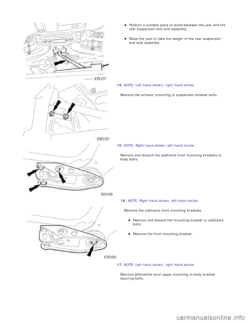
Position a suitable piece o
f wood between the jack and the
rear suspension and axle assembly.
Rai s
e the jack to take the weight of the rear suspension
and axle assembly.
14 . NOTE
: Left-hand shown, right-hand similar
Remove the exhaust mounting to suspension bracket bolts.
15 . NOTE
: Right-hand shown, left-hand similar
Remove and discard the subframe front mounting brackets to
body bolts.
16 . NOTE
: Right-hand shown, left-hand similar
Remove the subframe front mounting brackets.
Remove an d discard the mount
ing bracket to subframe
bolts.
R e
move the front mounting bracket.
17. NOTE: Left-hand shown, right-hand similar
Remove differential strut upper mounting to body bracket
securing bolts.
Page 175 of 2490
I
nstallation
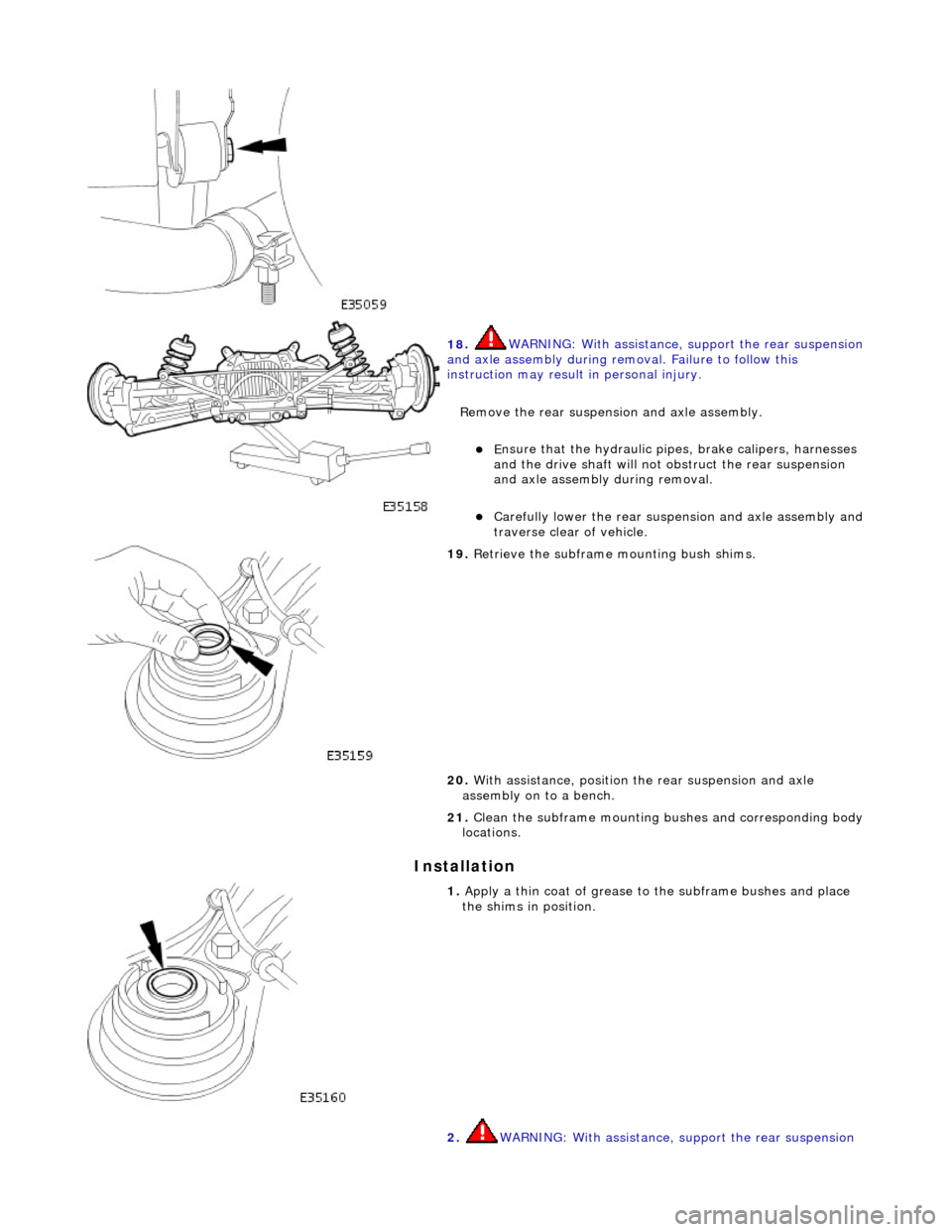
18
.
WARNING: With assistance, support the rear suspension
and axle assembly during remo val. Failure to follow this
instruction may result in personal injury.
Remove the rear suspensi on and axle assembly.
E
nsure that the hydr
aulic pipes, brake calipers, harnesses
and the drive shaft will not obstruct the rear suspension
and axle assembly during removal.
Carefull
y lower the rear suspen
sion and axle assembly and
traverse clear of vehicle.
19
.
Retrieve the subframe mounting bush shims.
20. With assistance, position th e rear suspension and axle
assembly on to a bench.
21. Clean the subframe mounting bushes and corresponding body
locations.
1. Apply a th
in coat of grease to the subframe bushes and place
the shims in position.
2. WARNING: With assistance, support the rear suspension
Page 177 of 2490

Inst
all new inner mounting bracket bolts.
Ti
ghten to 88-118 Nm.
8. NOTE
: Right-hand shown, left-hand similar
Tighten to 88-118 Nm.
9. NOTE
: Right-hand shown, left-hand similar
Install new different ial strut to body bracket bolts.
Tigh
ten to 68-92 Nm.
10. Lower and remove trolley jack.
11
.
Attach the drive shaft to the flexible coupling.
Align the marks previously pain
ted on drive shaft and
flexible coupling.
Inst
all new drive shaft coupling bolts and nuts.
12. Tighten to 76-88 Nm.
Page 182 of 2490

Withdraw th
e hub carrier and support on a block of wood.
9. CAUTIO
N: Note the position of
the shims during removal.
They must be returned to th eir original position during
installation.
Noting their positions, remove the shim from each end of the
pivot pin sleeve.
10 . WAR
NINGS:
ENSURE THE SPECIAL TOOLS ARE POSITIONED
DIAMETRICALLY OPPOSITE ON THE SPRING AND THE ARMS ARE
CORRECTLY SEATED .
WHEN COMPRESSING THE SPRING, TIGHTEN THE
SPECIAL-TOOL ADJUSTMENT BOLTS EVENLY.
Compress the spring.
Install and alig n th
e special
tools 204-179 diametrically
opposite on the spring.
Eve n
ly tighten the special tool tensioning bolts to
compress the spring.
11 . R
emove the shock absorber to
wishbone mounting nut and
bolt.
12. Remove the nuts securing th e shock absorber and spring
upper mounting to the body.
Page 188 of 2490
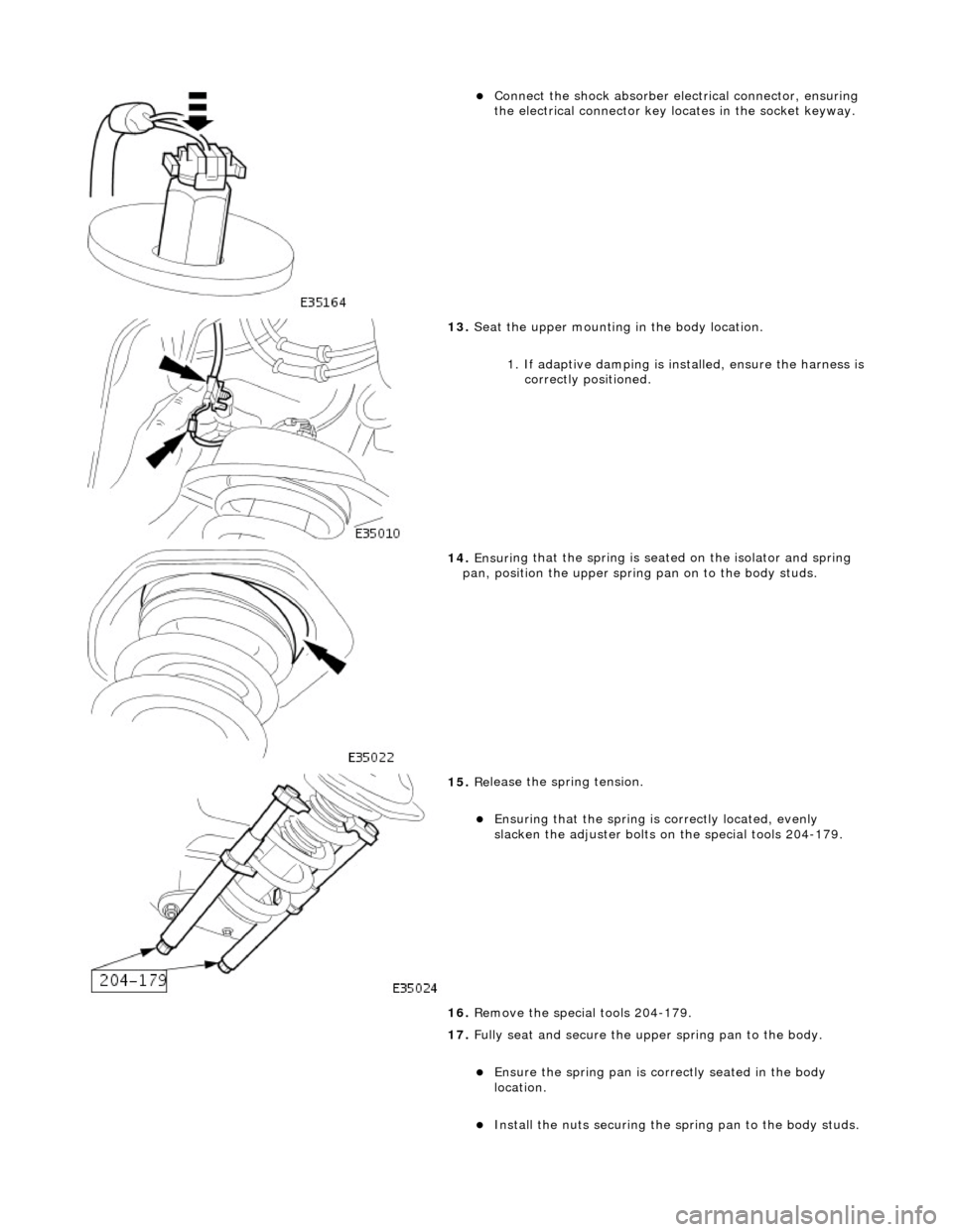
Connect
the shock absorber elec
trical connector, ensuring
the electrical connector key locates in the socket keyway.
13. Seat
the upper mounting in the body location.
1. If adaptive damping is installed, ensure the harness is
correctly positioned.
14 . Ensuri
ng that the spri
ng is seated on the isolator and spring
pan, position the u pper spring pan on to the body studs.
15 . Re
lease the spring tension.
Ensuri
ng that the spri
ng is
correctly located, evenly
slacken the adjuster bolts on the special tools 204-179.
16. Remove the special tools 204-179.
17. Fully seat and secure the u pper spring pan to the body.
Ensure the spring pan i
s correctly seated in the body
location.
Inst al
l the nuts securing the sp
ring pan to the body studs.