climate control JAGUAR X308 1998 2.G User Guide
[x] Cancel search | Manufacturer: JAGUAR, Model Year: 1998, Model line: X308, Model: JAGUAR X308 1998 2.GPages: 2490, PDF Size: 69.81 MB
Page 980 of 2490
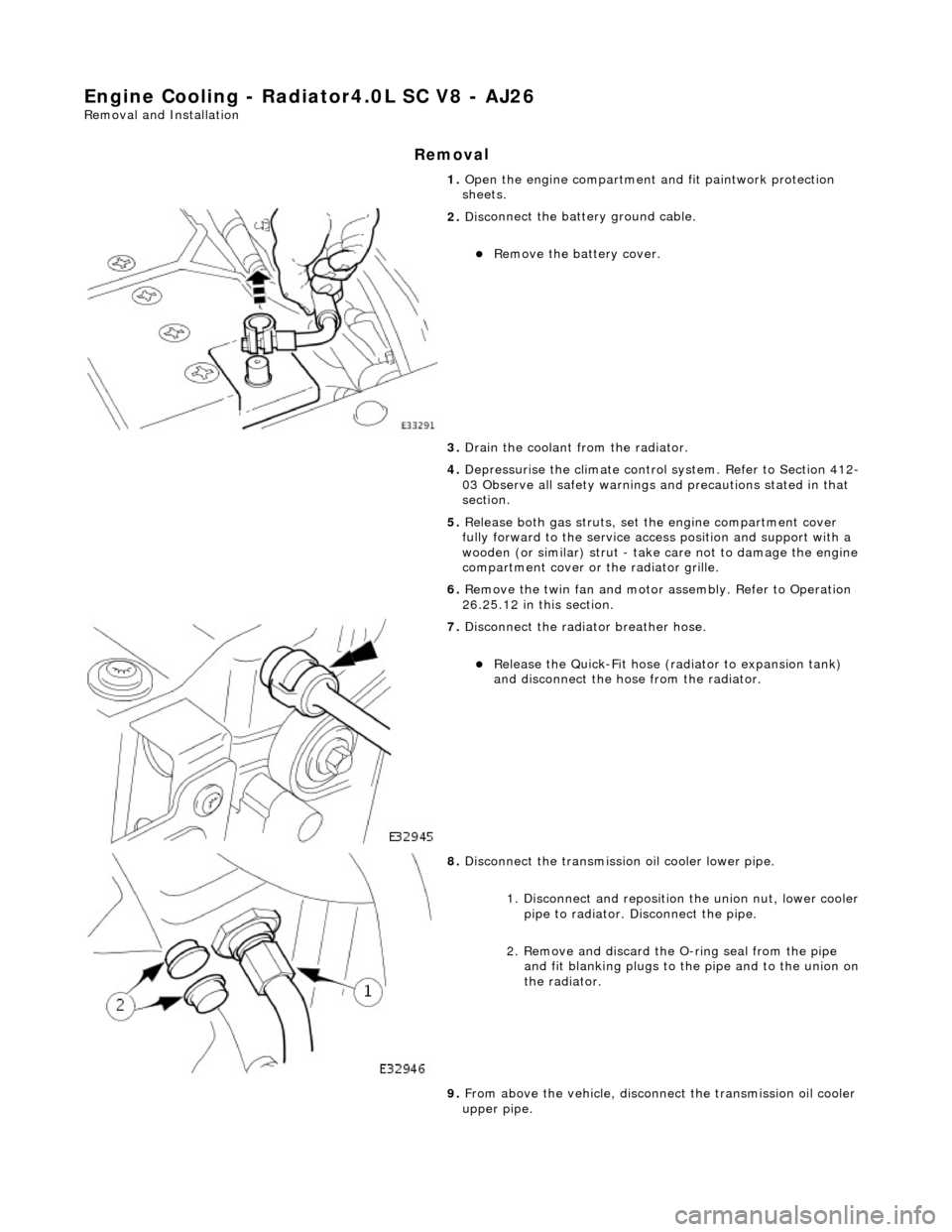
Engine Cooling - Radiator4.0L SC V8 - AJ26
Remo
val and Installation
Remov
a
l
1.
Op
en the engine compartment and fit paintwork protection
sheets.
2. Disc
onnect the batt
ery ground cable.
пЃ¬Re
move the battery cover.
3. Drain the coolant from the radiator.
4. Depressurise the climate control system. Refer to Section 412-
03 Observe all safety warnings and precautions stated in that
section.
5. Release both gas struts, set the engine compartment cover
fully forward to the service acce ss position and support with a
wooden (or similar) strut - take care not to damage the engine
compartment cover or the radiator grille.
6. Remove the twin fan and motor assembly. Refer to Operation
26.25.12 in this section.
7. Di
sconnect the radiator breather hose.
пЃ¬R
e
lease the Quick-Fit hose (radiator to expansion tank)
and disconnect the hose from the radiator.
8. Disc
onnect the transmission oil cooler lower pipe.
1. Disconnect and reposition the union nut, lower cooler pipe to radiator. Di sconnect the pipe.
2. Remove and discard the O- ring seal from the pipe
and fit blanking plugs to the pipe and to the union on
the radiator.
9. From above the vehicle, disconne ct the transmission oil cooler
upper pipe.
Page 1501 of 2490

Selector lever:
Gear selector positions are:
пЃ¬P Transmission mechanically locked, starting available * пЃ¬R Reverse gear пЃ¬N Neutral gear, no power to the rear wheels (starting available) пЃ¬D Drive gear, all 5 forward gears available (see Performance Mode Pushbutton) пЃ¬4 Upshift to 4th gear only пЃ¬3 Upshift to 3rd gear only пЃ¬2 Upshift to 2nd gear only
Gearshift Interlock Manual Override*
The interlock system which locks the sele ctor in P and prevents the ignition key from being removed except when P is
selected, may be manually overridden in the event of an emergency.
1. 1. With the parking brake applied
2. 2. Remove the access blank using a suitable Torx bit
3. 3. Insert a small screwdriver into the vacated hole
4. 4. Push the screwdriver downwards, gently, and hold whilst simultaneously moving the selector from P towards R ,
but do not engage R until the tool has been removed
5. 5. An audible warning may be heard when operation 4 is carried out
6. 6. With the selector in N and the access bl ank replaced, the vehicle may be started
Range Selection
пЃ¬The selector lever transmits operator demand to the transmission and TCM by means of a cable and Dual-Linear
Switch (DLS).
пЃ¬The lever operates the transmission assemb ly selector shaft, only for P R N D , by means of a cable. Movement of the
lever across the gate to 4, 3 and 2 positions disengages th e cable from the selector lever and engages the DLS which
controls gear selection electronically.
Gear selector module:
пЃ¬Provides illumination of the decal relevant to the gear sele cted. This information is provided by CAN from the TCM. пЃ¬Illuminates the security system Active LED on the gear selector surround, in response to an output from the BPM.
Transmission Switches
Performance Mode Pushbutton
7—Connector - Climate control
8—Solenoid - Gear selector
9—Security system Active LED
Page 1752 of 2490
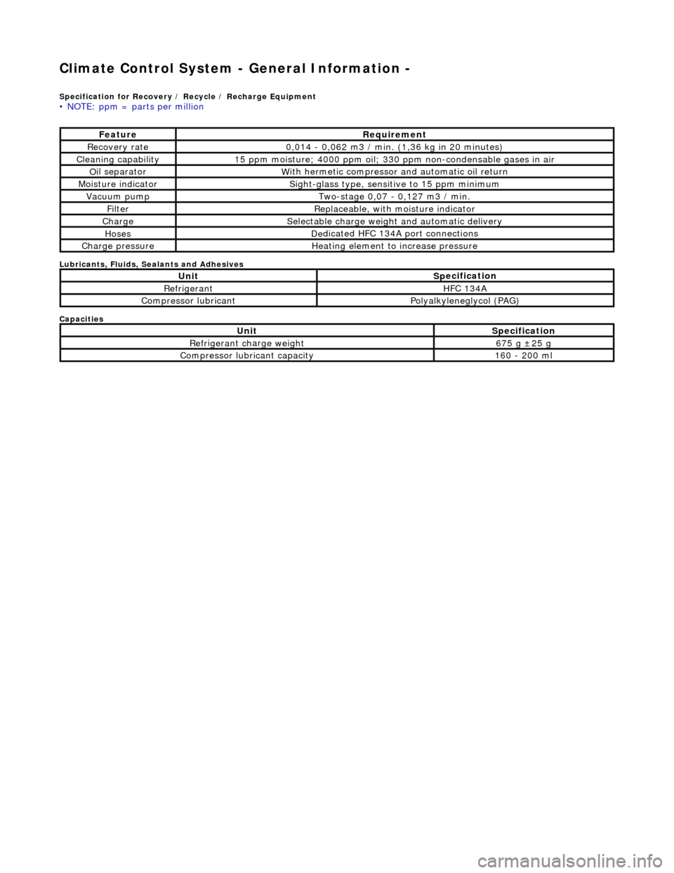
Climate Control System - General Informatio
n -
Sp
ecification for Recovery / Recycle / Recharge Equipment
•
NOTE: ppm = parts per million
Lubri
c
ants, Fluids, Sealants and Adhesives
Capacities
Fe at
ure
R
e
quirement
R
e
covery rate
0
,
014 - 0,062 m3 / min. (1,36 kg in 20 minutes)
Cleaning capability1
5 ppm
moisture; 4000 ppm oil; 330 ppm non-condensable gases in air
O
il se
parator
W
i
th hermetic compressor
and automatic oil return
Mois
ture indicator
Sigh
t-glass type, sensit ive to 15
ppm minimum
Vacuu
m
pump
Two-s
t
age 0,07 - 0,127 m3 / min.
Fi
lt
er
Replaceable, w
i
th
moisture indicator
ChargeSele
ctable charge weight and automatic delivery
HosesD
e
dicated HFC 134A port connections
Charge pressu
reHe
ating element to increase pressure
UnitS
p
ecification
Re
fr
i
geran
tHFC 134
A
Compressor lubricantP
ol
yalkyleneglycol (PAG)
UnitS
p
ecification
Re
fr
i
geran
t ch
ar
ge we
ight675 g В±2 5 g
Compressor lubricant capacity160
- 200 ml
Page 1753 of 2490

Climate Co
ntrol System - General In
formation - Climate Control System
Description an
d Operation
CAUTION: Observe all relevant safety requirements. Wear suitable eye and skin protection Do not mix HFC 134A and
CFC 12 refrigerants. Do not vent refrigerant directly to atmosphere and always use Jaguar approved recovery, recycle and
recharge equipment. Note the amount of recovered refrigerant; it will indicate the state of the system.
Working Practices
Be aware o
f, and comply with al
l health and safety requirements , whether they be legislative or common sense. This applies
to conditions set both for the operator and workshop.
Before commencing any repair or service procedure, disconnect the vehicle battery ground lead and protect the vehicle,
where appropriate, from dirt or damage.
Work in a well ventilated, clean and tidy area.
Keep all components and tools clean.
Recovery, recycle and recharge equipment must meet, or ex ceed, the requirements detailed in the Specification sub-
section.
Handling Refrigerant
We
ar eye protection at all times. Use gloves and keep all
skin covered that may come into contact with refrigerant.
Should refrigerant come into co ntact with eyes or skin, wash the affected area with cool water and seek medical advice; do
not attempt to treat the condition yourself.
Avoid breathing refrigerant vapor; it may cause irritation to the respiratory system.
CAUTION: Never use high pressure comp ressed air to flush out a system. Under certain ci rcumstances a combination
of HFC 134A refrigerant, compressed air and a source of combus tion (welding and brazing operations in the vicinity), may
result in an explosion and the release of potentially toxic compounds.
HFC 134A and CFC 12 refrigerants must neve r come into contact with each other. They will form an inseparable mixture
which can only be disposed of by incineration.
Do not vent refrigerant directly to atmo sphere; always use Jaguar approved recove ry equipment. Never depress the charge
or discharge port valves to check for the pr esence of refrigerant.
HFC 134A refrigerant is fully recycleable and it may be 'cleaned' by the recovery equipment and therefore re-used following
removal from a system.
Page 1758 of 2490
Climate Control System - General Informatio
n - Climate Control System
D
iagn
osis and Testing
I
n
troduction
It is very i
m
portant to positive
ly identify the area of concern before starting a rectification procedure. A little time spent with
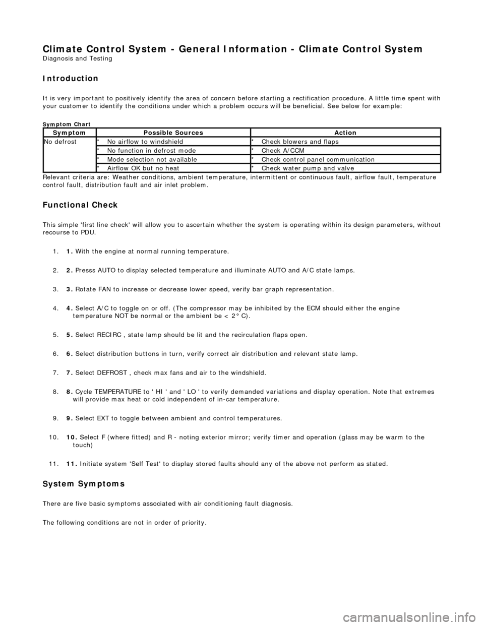
your customer to identify the conditions under which a pr oblem occurs will be beneficial. See below for example:
Sym
ptom Chart
Re
lev
ant criteria are: Weather conditions,
ambient temperature, intermittent or cont inuous fault, airflow fault, temperature
control fault, distribution fault and air inlet problem.
Functio n
al Check
This
s
imple 'first line check' will allo
w you to ascertain whether the system is operating within its design parameters, withou t
recourse to PDU.
1. 1. With the engine at normal running temperature.
2. 2. Presss AUTO to display selected temperature and illuminate AUTO and A/C state lamps.
3. 3. Rotate FAN to increase or decrease lowe r speed, verify bar graph representation.
4. 4. Select A/C to toggle on or off. (T he compressor may be inhibited by the ECM should either the engine
temperature NOT be normal or the ambient be < 2В° C).
5. 5. Select RECIRC , state lamp should be lit and the recirculation flaps open.
6. 6. Select distribution butt ons in turn, verify correct air distribution and relevant state lamp.
7. 7. Select DEFROST , check max fans and air to the windshield.
8. 8. Cycle TEMPERATURE to ' HI ' and ' LO ' to verify demanded variations and display operation. Note that extremes
will provide max heat or cold independent of in-car temperature.
9. 9. Select EXT to toggle between am bient and control temperatures.
10. 10. Select F (where fitted) and R - noting exterior mirror; verify timer and operation (glass may be warm to the
touch)
11. 11. Initiate system 'Self Test' to display stored faul ts should any of the above not perform as stated.
Sy
stem Symptoms
There
are five
basic symptoms associated
with air conditioning fault diagnosis.
The following conditions are not in order of priority.
Sy m
ptom
Possib
l
e Sources
Acti
o
n
N
o defrostN o
airflow to windshield
*
Check blower s and flaps
*
N o functi
on in defrost mode
*
Check A/CCM
*
Mo de s
election not available
*
Chec k
control panel communication
*
Ai rfl
ow OK but no heat
*
Check water pu
mp and valve
*
Page 1762 of 2490
Climate Control System - General Infor
mation - Air Conditioning (A/C)
System Recovery, Evacuation and Charging
Gen e
ral Procedures
Recover / Reclaim
Ev
acuation
Charging
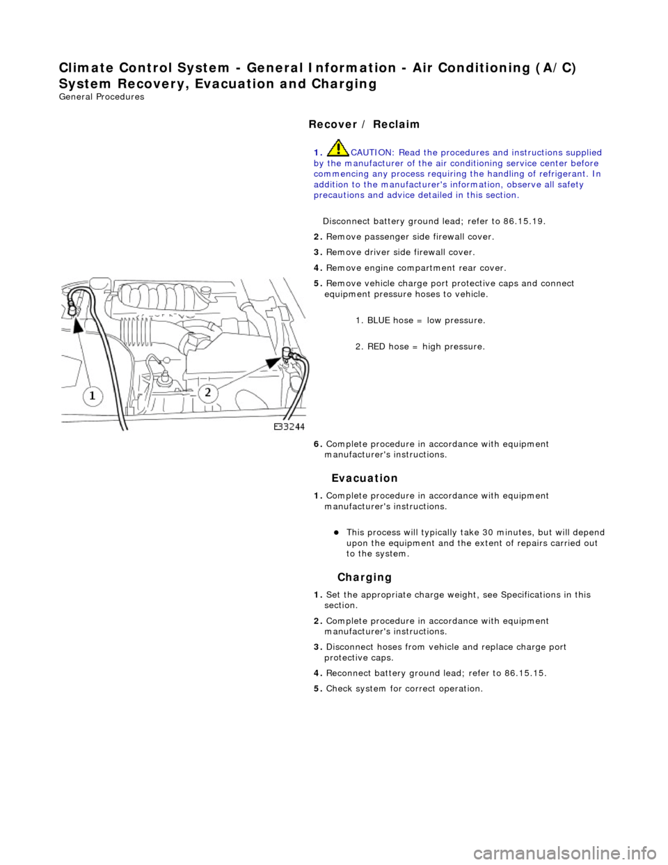
1.
CAUTIO
N: Read the procedures and instructions supplied
by the manufacturer of the air co nditioning service center before
commencing any process requiring the handling of refrigerant. In
addition to the manufacturer's in formation, observe all safety
precautions and advice deta iled in this section.
Disconnect battery ground lead; refer to 86.15.19.
2. Remove passenger side fi
rewall cover.
3. Remove driver side firewall cover.
4. Remove engine compar tment rear cover.
5. Re
move vehicle charge port
protective caps and connect
equipment pressure hoses to vehicle.
1. BLUE hose = low pressure.
2. RED hose = high pressure.
6. Complete procedure in ac cordance with equipment
manufacturer's instructions.
1. Complete procedure in ac cordance with equipment
manufacturer's instructions.
пЃ¬This proc
ess will typically ta
ke 30 minutes, but will depend
upon the equipment and the ex tent of repairs carried out
to the system.
1. Set the appropriate charge weight, see Specifications in this
section.
2. Complete procedure in ac cordance with equipment
manufacturer's instructions.
3. Disconnect hoses from vehicle and replace charge port
protective caps.
4. Reconnect battery ground lead; refer to 86.15.15.
5. Check system for correct operation.
Page 1766 of 2490
Climate Control System - General Informatio
n - Refrigerant Oil Adding
Gen
e
ral Procedures
CAUTION: Always decant fresh oil from a sealed container and do not leave oil exposed to the atmosphere. PAG oil is
very hygroscopic (absorbs wate r) and will rapidly attract atmospheric moisture. PAG oil must NEVER be mixed with mineral
based oils. Do not re-use oil following a recovery cycle, dispose of it safely.
Original Compressor
New Compressor
1. The amount of oi
l drawn out during a recovery procedure will
be dependent on the state of the system and the rate of
recovery. The quantity will be a pproximately 30 to 40 ml.; this
may vary, and the figure is given only for guidance.
The oil separator vessel in the recovery equipment must be
clean and empty at the start of the process, so that the quantity
of oil which is drawn out may be accurately measured.
• NOTE: The equipment manufactu rer's instructions must be
followed when adding oil directly into an original, or new unit,
owing to rectification work to the existing compressor, or the
need to fit a new compressor.
Oil may be added to the system either via the recovery, recycle
and recharge station or by us ing a proprietary oil injector.
Alternatively, if the compress or has been removed from the
vehicle, the oil may be added directly to the compressor.
1. From an existing compressor, drain the oil into a measuring
cylinder and record the amount. Fl ush the unit out with fresh oil
and drain thoroughly. Replenish the compressor with the same
amount of oil that was originally drained out and immediately
plug all orifices ready for refitting to the vehicle.
1. Drain and discard th e transit lubricating oil from the new
compressor before it is be fitted.
To avoid over-filling the system, an allowance must be made for
the quantity of oil found in the original compressor and the
quantity deposite d in the recovery equipment oil separator from
the charge recovery operation.
Typical example:
пЃ¬D rained
from original compressor - 50 ml.
пЃ¬R
e
covered from oil separator - 40 ml.
пЃ¬Q
u
antity to be put in new compressor - 50 + 40 = 90 ml.
2. The difference between the combined total quantity of
recovered and drained oil and the nominal capacity of the
system (180 ml.), is due to th e quantity of oil remaining in
components such as the cond enser, receiver drier or
evaporator. This oil is no t normally recoverable.
The same procedure may be followed if a problem has occurred
due to oil leakage, as the amount of oil lost is generally small. If
the recovery process has no t been necessary, because
refrigerant has also been lost, then only the quantity drained
from the original compress or needs to be replaced.
Page 1768 of 2490

Climate Control System - General Infor
mation - Refrigerant System Tests
Gen
e
ral Procedures
WARNING: USE EXTREME CARE AND OBSERVE ALL SAFETY PRECAUTIONS RELATED TO THE USE OF REFRIGERANTS.
FAILURE TO FOLLOW THIS INSTRUCTION MAY RESULT IN PERSONAL INJURY.
CAUTION: The A/C refrigerant analyzer mu st be used before the recovery of any vehicle' s A/C refrigerant. Failure to
do so puts workshop bulk refrigerant at risk of contamination. If the vehicle A/C refrigerant is contaminated, refer the
customer to return to the repair facility that carried out the last A/C repair. If the customer wishes to pay the additional
cost, use the A/C recovery equipment that is designated for recovering contaminated A/C refrige rant. All contaminated A/C
refrigerant must be disposed of as hazardous waste. To prevent possible pe rsonal injury, for all equipment, follow the
equipment manufacturer's procedures and instructions.
• NOTE: Jaguar Cars Ltd. supports the effi cient usage, recovery and recycling of the refrigera nt used in passenger car air
conditioners. Jaguar Cars Ltd. recommend s the use of UL-approved recovery/recycling equipment during any A/C system
repair and recharge procedure which requ ires that the system be evacuated.
1. Us
e UL-approved recovery/recycling equipment to evacuate
and recover the A/C system.
пЃ¬Follow t h
e equipment manufacturer's procedures and
instructions for use of equipment.
Page 1798 of 2490
Air Conditioning - Air Conditioning
Description and Operation
Introduction
Parts List
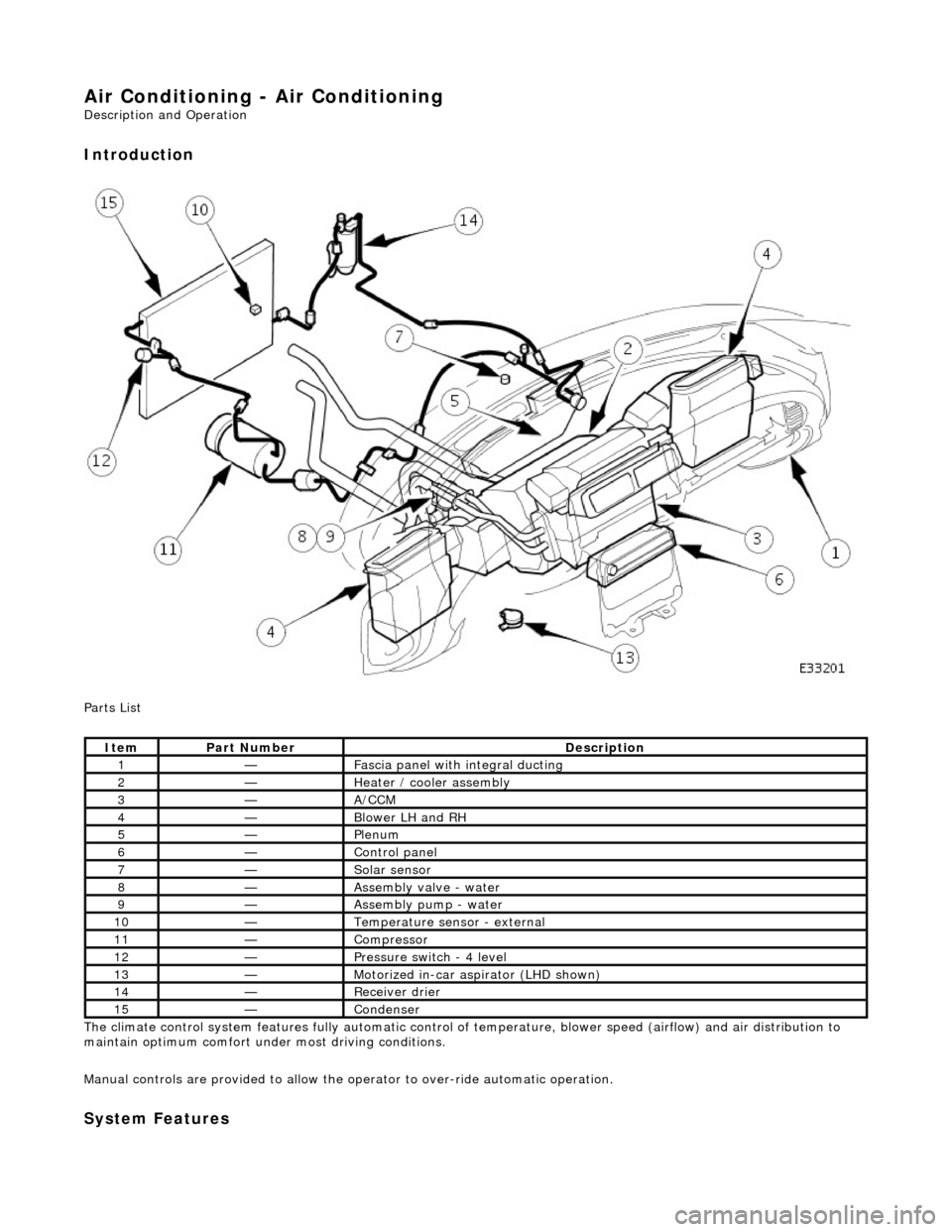
The climate control system features fully automatic control of temperature, blower speed (airflow) and air distribution to
maintain optimum comfort under most driving conditions.
Manual controls are provided to allow the operator to over-ride automatic operation.
System Features
ItemPart NumberDescription
1—Fascia panel with integral ducting
2—Heater / cooler assembly
3—A/CCM
4—Blower LH and RH
5—Plenum
6—Control panel
7—Solar sensor
8—Assembly valve - water
9—Assembly pump - water
10—Temperature sensor - external
11—Compressor
12—Pressure switch - 4 level
13—Motorized in-car aspirator (LHD shown)
14—Receiver drier
15—Condenser
Page 1821 of 2490

Control Components - Control Components
Description and Operation
System Controls
The climate control system is controlled by : 1. 1. Manual input from the operator, via the center console located control panel.
2. 2. Automatically by means of the A/CCM.
Output is based upon input from the following devices:
пЃ¬Motorized In-car aspirator пЃ¬External air temperature sensor пЃ¬Coolant temperature sensor пЃ¬Heater 'air-off' (the temperature of the air leaving the matrix fins) temperature sensor пЃ¬Evaporator 'air-off' (the temperature of the air leaving the evaporator fins) temperature sensor пЃ¬Solar sensor пЃ¬Left hand blower recirculation / fresh air flap potentiometer пЃ¬Right hand blower recirculation / fresh air flap potentiometer пЃ¬Upper air distribution box (ADB) center and side face flap servomotor potentiometer пЃ¬ADB defrost flap servomotor potentiometer пЃ¬Air conditioning unit Foot flap servomotor potentiometer пЃ¬Air conditioning unit Cool Air Bypass flap servomotor potentiometer пЃ¬Thumbwheel controls on the facia vent assemblies which provide manu al adjustment of the airflow volume. пЃ¬Road and engine speed signals input to the A/CCM
Climate Control Panel
Communication between the control panel and the A/CCM is via a serial data communications link.
Switching the Climate Control system ON
The climate control system can be switched ON by pressing one of the following :
Ref #1 On / Off (resumes the system on in the previous settings).
Ref #10 A / C (resumes the system on in the previous settings).
Ref #11 AUTO (resumes the system on at the previous temperature setting).