lower JAGUAR X308 1998 2.G User Guide
[x] Cancel search | Manufacturer: JAGUAR, Model Year: 1998, Model line: X308, Model: JAGUAR X308 1998 2.GPages: 2490, PDF Size: 69.81 MB
Page 66 of 2490
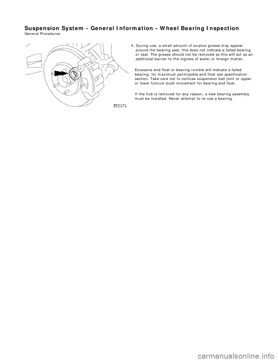
Suspension System - General Information - Wheel Bearing Inspection
Gene
ral Procedures
1.
Dur
ing use, a small amount of surplus grease may appear
around the bearing seal, this does not indicate a failed bearing
or seal. The grease should not be removed as this will act as an
additional barrier to the ingress of water or foreign matter.
Excessive end float or bearing ru mble will indicate a failed
bearing; for maximum permissibl e end float see specification
section. Take care not to confuse suspension ball joint or upper
or lower fulcrum bu sh movement for bearing end float.
If the hub is removed for any reason, a new bearing assembly
must be installed. Never at tempt to re-use a bearing.
Page 67 of 2490
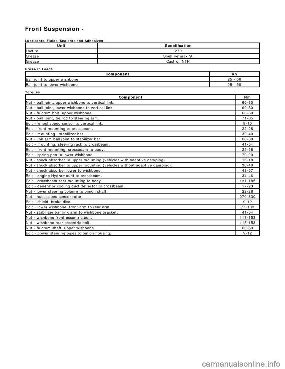
Front Suspension -
Lubri
cants, Fluids, Sealants and Adhesives
Press-In Loads
Torques
UnitS
pecification
Loctite27
0
Greas
e
Shell Retin
ax 'A'
Greas
e
Castro
l 'NTR'
Com
ponent
Kn
Ball join
t to upper wishbone
25
- 50
B
all joint to lower wishbone
25
- 50
Com
ponent
Nm
N
ut - ball joint, upper wishbone to vertical link.
60
-80
N
ut - ball joint, lower wishbone to vertical link.
60
-80
Nu
t - fulcrum bolt, upper wishbone.
60
-80
N
ut - ball joint, tie rod to steering arm.
71
-85
Bol
t - wheel speed sensor to vertical link.
8-1
0
Bol
t - front mounting to crossbeam.
22
-28
Bolt
- mounting , stabilizer bar.
30
-40
N
ut - link arm ball joint to stabilizer bar.
60
-80
Bolt
- mounting, steering rack to crossbeam.
41
-54
B
olt - front mounting, crossbeam to body.
22
-28
Bol
t - spring pan to lower wishbone.
70
-90
N
ut - shock absorber to upper mounting
(vehicles with adaptive damping).
16
-18
Nu
t - shock absorber to upper mounting (vehicles without adaptive damping).
30
-40
N
ut - shock absorber lower to wishbone.
43
-57
B
olt - engine Hydramount to crossbeam.
34
-46
B
olt - crossbeam rear mounting to body.
13
1-185
Bol
t - generator cooling du
ct deflector to crossbeam.
17
-23
N
ut - lower steering column to pinion shaft.
22
-28
N
ut - hub, speed sensor rotor.
27
0-330
B
olt - shield, brake disc.
9-1
2
Bol
t - lower wishbone, front arm to rear arm.
77
-103
Nu
t - stabilizer bar link arm to wishbone bracket.
41
-54
N
ut - wishbone front
eccentric bolt.
11
3-153
Nu
t - wishbone rear
eccentric bolt.
11
3-153
N
ut - fulcrum shaft, upper wishbone.
60
-80
Bolt -
power steering pi
pes to pinion housing.
9-1
2
Page 69 of 2490
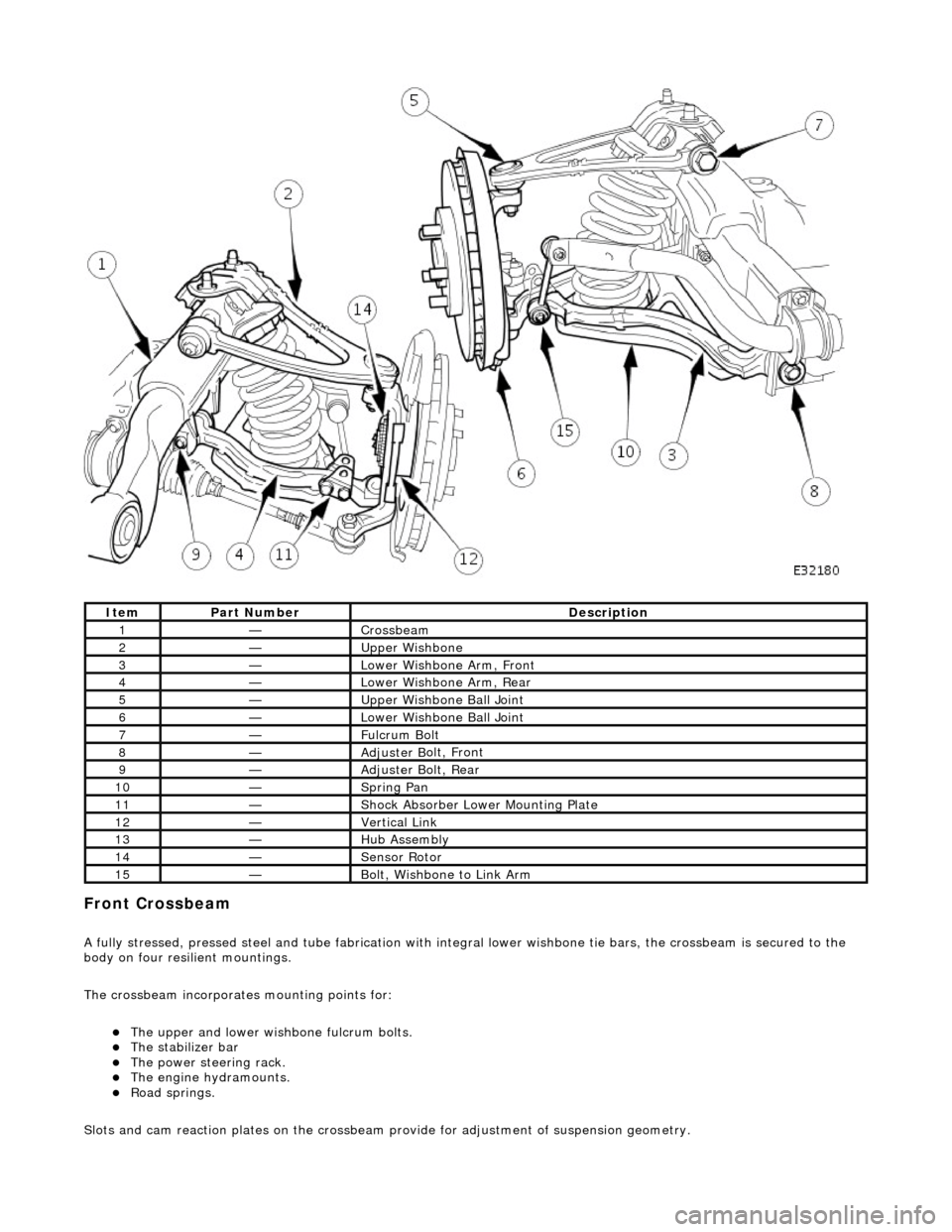
Front C
rossbeam
A
fully stressed, pressed steel and tube fa
brication with integral lower wishbone tie bars, the crossbeam is secured to the
body on four resilient mountings.
The crossbeam incorporates mounting points for:
The u
pper and lower wish
bone fulcrum bolts.
The
stabilizer bar
The power steering rack. The engine h
ydramounts.
R
oad springs.
Slots and cam reaction pl ates on the crossbeam provide for ad justment of suspension geometry.
It
em
Par
t Number
De
scription
1—Cro
ssbeam
2—Upper
Wishbone
3—Lower Wi
shbone Arm, Front
4—Lower Wi
shbone Arm, Rear
5—Upper
Wishbone Ball Joint
6—Lower Wi
shbone Ball Joint
7—Ful
crum Bolt
8—Adjuster B
olt, Front
9—Adjuster B
olt, Rear
10—S
pring Pan
11—Shock Absorber Lower M
ounting Plate
12—Vertical Link
13—Hub Assembly
14—Sensor R
otor
15—B
olt, Wishbone to Link Arm
Page 70 of 2490
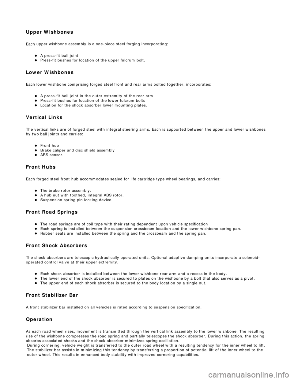
Upper
Wishbones
Each
upper wi
shbone assembly is a on
e-piece steel forging incorporating:
A pres
s-fit ball joint.
Press-fi
t bushes for location of the upper fulcrum bolt.
Lower Wishbones
Each l
o
wer wishbone comprising
forged steel front and rear arms bolted together, incorporates:
A p
ress-fit ball joint in the outer extremity of the rear arm.
Press-f
i
t bushes for location of the lower fulcrum bolts
Locati
on for the shock absor
b
er lower mounting plates.
Vertica l Links
The vertical
links are of forged steel
wi
th integral steering arms. Each is suppo rted between the upper and lower wishbones
by two ball joints and carries:
Front hub
Brake ca
liper and disc shield assembly
ABS se
nsor
.
Front Hub
s
Each f
o
rged steel front hub accommodates sealed for life cartridge
type wheel bearings, and carries:
The brake rotor assembl
y.
A
h
ub nut with toothed, integral ABS rotor.
Su
s
pension spring pi
n locking device.
Front Road
Springs
The road spri
ng
s are of coil type with their
rating dependent upon vehicle specification
Ea
ch spring is installed between the suspension crossbeam location and the lower wishbone spring pan.
Ru
bber seats ar
e installed betw
een the spring and the crossb eam and the spring pan.
Front Shock A
bsorbers
Th
e
shock absorbers are telescopic hydrau
lically operated units. Optional adaptive damping units incorporate a solenoid-
operated control valve at their upper extremity.
Each shoc
k absorber is installed between the lowe
r wishbone rear arm and a recess in the body.
The l
o
wer end of the shock absorber is se
cured to plates on the wishbone by a bolt that also serves as a pivot.
The u
pper en
d of each shock absorber is secured to the body location by a single nut.
Front Sta
b
ilizer Bar
A
front stabil
izer bar installed on all vehicles
is rated according to suspension specification.
Opera
tion
As each road wheel r
i
ses, move
ment is transmitted through the vertical link assembly to the lower wishbone. The resulting
rise of the wishbone compresses the road spring and partially telescopes the shock absorber. During this action, the spring
absorbs associated shocks and the shock absorber minimizes sprin
g os c
illation.
Du
ring cornering, vehicle weight
is transferred to the outer road wheel with a resulting tendency for the inner wheel to lift.
The stabilizer bar assists in minimizing this tendency by transf erring a proportion of potential lift of the inner wheel to the
outer wheel. This result s in enhanced body stability with improved corner ing capabilities.
Page 72 of 2490
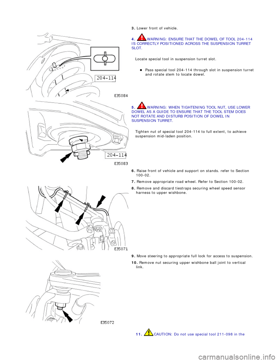
3. Lower front of vehicl
e.
4. W
A
RNING: ENSURE THAT THE DOWEL OF TOOL 204-114
IS CORRECTLY POSITIONED ACROSS THE SUSPENSION TURRET
SLOT.
Locate special tool in suspension turret slot.
Pas s
special tool 204-114 thro
ugh slot in suspension turret
and rotate stem to locate dowel.
5. WARNING: WHE N
TIGHTENING
TOOL NUT, USE LOWER
DOWEL AS A GUIDE TO ENSURE THAT THE TOOL STEM DOES
NOT ROTATE AND DISTURB POSITION OF DOWEL IN
SUSPENSION TURRET.
Tighten nut of special tool 204-114 to full extent, to achieve
suspension mid-laden position.
6. Ra
ise front of vehicle and support
on stands. refer to Section
100-02.
7. Remove appropriate road wheel. Refer to Section 100-02.
8. Remove an d discard tiestraps se
curing wheel speed sensor
harness to upper wishbone.
9. Move steering to appropriate full lock for access to suspension.
10 . R
emove nut securing upper wish
bone ball joint to vertical
link.
11. CAUTION: Do not use special tool 211-098 in the
Page 73 of 2490

f
ollowing procedure as this will
damage the ball joint gaiter.
Release wishbone ball joint from vertical link.
1. Install special tool 204-192 on upper wishbone ball joint.
2. Tighten bolt of special tool to release ball joint
taper from vertical link.
12. Remove special tool from ball joint.
13
.
Lift upper wishbone to withdraw ball joint from vertical link.
14
.
To prevent damage to lower ball joint, secure vertical link to
road spring using strong wire.
15
.
Remove upper wishbone fulcrum nut and bolt and withdraw
wishbone from vehicle.
16. Secure upper wishbone in a vise.
17. Using a hacksaw, partially cut through two diametrically
opposite segments of ball joint flange.
Page 77 of 2490
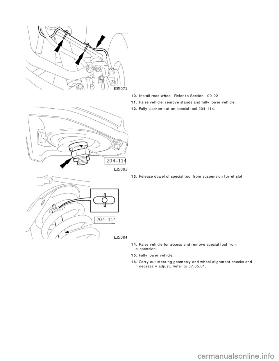
10
.
Install road wheel. Re fer to Section 100-02
11. Raise vehicle, remove stands and fully lower vehicle.
12
.
Fully slacken nut on special tool 204-114.
13
.
Release dowel of special tool from suspension turret slot.
14. Raise vehicle for access an d remove special tool from
suspension.
15. Fully lower vehicle.
16. Carry out steering geometry an d wheel alignment checks and
if necessary adjust. Refer to 57.65.01.
Page 78 of 2490

Front Suspension - Rear Lower Arm
Remo
val and Installation
Remov
a
l
CAUTI
O
N: Replacement of
nuts and bolts: Various thread-locking devices are used on nuts and bolts throughout the
vehicle. These devices restrict the number of times a nut or bolt can be used. Refer to Section 100-00 for further
information.
S p
ecial Tool(s)
R
o
ad spring compressor
204-111 (JD115)
Taper separator
2
11-098 (JD 100)
Ball
Jo
int Taper Separator
204-192 (JD 219)
Bal l
joint splitter
204-293
1. Ra
ise front of vehicle and support on stands. Refer to Section
100-02.
2. Remove appropriate road wheel. Refer to Section 100-02.
3. CAUTIO
N: Do not suspend caliper from brake hose as
this will damage the hose.
Remove brake calipers from carriers. 1. Remove caliper spring clip.
2. Remove guide pin dust caps.
3. Slacken and withdraw guide pins.
4. Remove caliper from carrier and tie to suspension mounting bracket.
4. Ra
ise vehicle further to provid
e access for Special Tool 204-
Page 79 of 2490

1
11 and support on stands. Refer to Section 100-02.
5. Ins
tall Special Tool 204-111 in road spring.
Sl
acken tool adjuster to suit spring length.
Install adaptor
and thrust collar.
Posit
ion stem of tool in center of spring passing dowel
through slot in su spension turret.
6. R
otate stem of Special Tool to
position dowel across slot.
7. W
ARNING: WHEN TURNING TOOL ADJUSTER, ENSURE
THAT TOOL STEM DOES NOT ROTATE AND DISTURB POSITION
OF DOWEL IN SUSPENSION TURRET.
Rotate adjuster of Special Tool to tension spring.
8. R
emove spring pan to lower
wishbone securing bolts.
9. Rotate adjuster of Special Tool to release tension from spring.
Page 80 of 2490
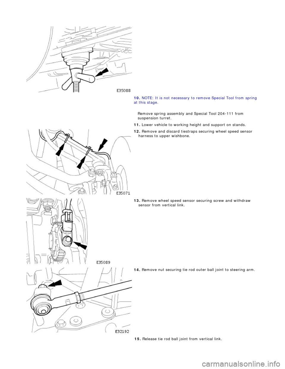
10. NOTE
: It is not necessary to re
move Special Tool from spring
at this stage.
Remove spring assembly and Special Tool 204-111 from
suspension turret.
11. Lower vehicle to working heig ht and support on stands.
12 . Remove an
d discard tiestraps
securing wheel speed sensor
harness to upper wishbone.
13 . R
emove wheel speed sensor se
curing screw and withdraw
sensor from vertical link.
14 . R
emove nut securing tie rod oute
r ball joint to steering arm.
15. Release tie rod ball joint from vertical link.