JAGUAR X308 1998 2.G Repair Manual
X308 1998 2.G
JAGUAR
JAGUAR
https://www.carmanualsonline.info/img/21/7640/w960_7640-0.png
JAGUAR X308 1998 2.G Repair Manual
Page 127 of 2490
Front Suspension - Front Stabiliz
er Bar Link
Re
moval and Installation
Remov
al
Installation
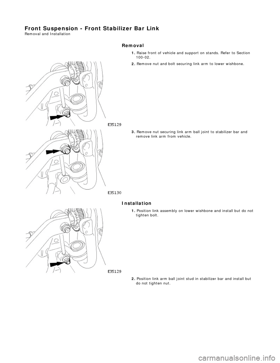
1. R
aise front of vehicle and support on stands. Refer to Section
100-02.
2. R
emove nut and bolt securing
link arm to lower wishbone.
3. R
emove nut securing link arm ba
ll joint to stabilizer bar and
remove link arm from vehicle.
1. Position li
nk assembly on lower
wishbone and install but do not
tighten bolt.
2. Position link arm ball joint stud in stabilizer bar and install but
do not tighten nut.
Page 128 of 2490
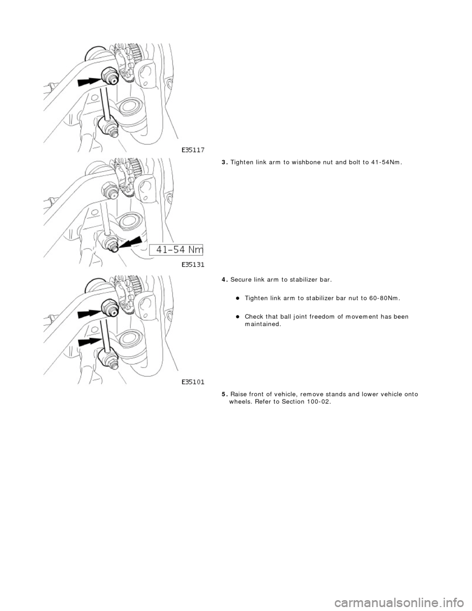
3.
Tighte
n link arm to wishbone
nut and bolt to 41-54Nm.
4. Secure li nk arm to stabil
izer bar.
Tigh
te
n link arm to stabilizer bar nut to 60-80Nm.
Check that ball
joi
nt freed
om of movement has been
maintained.
5. Raise front of vehicle, remove stands and lower vehicle onto
wheels. Refer to Section 100-02.
Page 129 of 2490

Front Suspension - Upper Arm Bushing
Re
moval and Installation
Remov
al
CAUTI
ON: Replacement of
nuts and bolts: Various thread-locking devices are used on nuts and bolts throughout the
vehicle. These devices restrict the number of times a nut or bolt can be used. See section 100-00 for information.
S
pecial Tool(s)
Ball
Joint Taper Separator
204-192 (JD 219)
Front Camber Tie-do
wn Link
204-114 (JD 133)
1. R
aise front of vehicle.
Refer to Section 100-02.
2. P
osition camber tie down spec
ial tool 204-114 on suspension.
Fully s
lacken tool adjuster nut.
Position too
l in road spring and pass upper dowel through
slot in suspen sion turret.
3. Lower front of vehicle.
4. R
otate stem of special tool 204-114 to locate dowel in
suspension turret slot.
5. WARNING: WHEN TIGHTENING TOOL NUT, USE LOWER
DOWEL AS A GUIDE TO ENSURE THAT THE TOOL STEM DOES
NOT ROTATE AND DISTURB POSITION OF DOWEL IN
SUSPENSION TURRET.
Fully tighten nut of special tool to achieve suspension mid-laden
Page 131 of 2490
I
nstallation
14
.
To prevent damage to lower ball joint, secure vertical link to
road spring using strong wire.
15
.
Remove upper wishbone fulcrum nut and shaft and withdraw
wishbone from crossbeam.
16. Secure upper wishbone in a vise.
17
.
Remove bush assemblies from wishbone.
1. Using a drift, remove thru st washer and spacer tube
from each inner and outer half-bush.
2. Remove inner and outer half bushes from wishbone.
Repeat
procedure to remove
remaining bush assembly.
18. Clean wishbone paying particular attention to bush locations.
19. Check that ball joint gaiter is not punctured or deeply
abraded.
1. Install thrust washer and spacer tube in first wishbone half-
bush.
Page 133 of 2490
11
.
Position wishbone to engage ball joint taper in vertical link.
12
.
Install nut securing ball joint to vertical link and tighten nut to
60-80Nm.
13
.
Reposition wheel speed sensor harness on wishbone and
secure with two tiestraps.
14. Fit road wheel. Refer to Section 100-02
15. Raise vehicle, remove stands and fully lower vehicle.
16. Fully slacken nut on special tool.
Page 134 of 2490
17.
R
elease dowel of special tool 204-114 from suspension turret
slot.
18. Raise vehicle for access an d remove special tool from
suspension.
19. Fully lower vehicle.
20. Carry out steering geometry an d wheel alignment checks and
if necessary adjust. Refer to 57.65.01.
Page 154 of 2490
THAT TOOL STEM
DOES NOT ROTATE AND DISTURB POSITION
OF DOWEL IN SUSPENSION TURRET.
Engage dowel of special tool 204-111 in suspension turret and
rotate to position across slot.
8. Lower vehicle onto stands.
9. Ro
tate tool adjuster to tension spring.
10 . R
emove wheel speed sensor se
curing screw and withdraw
sensor from vertical link.
11 . R
emove nut securing tie rod oute
r ball joint to steering arm.
12. Release ball joint from vertical link.
1. Install special tool 211-098 on tie rod outer ball joint.
2. Tighten tool bolt to rele ase taper pin from vertical
link.
Page 155 of 2490
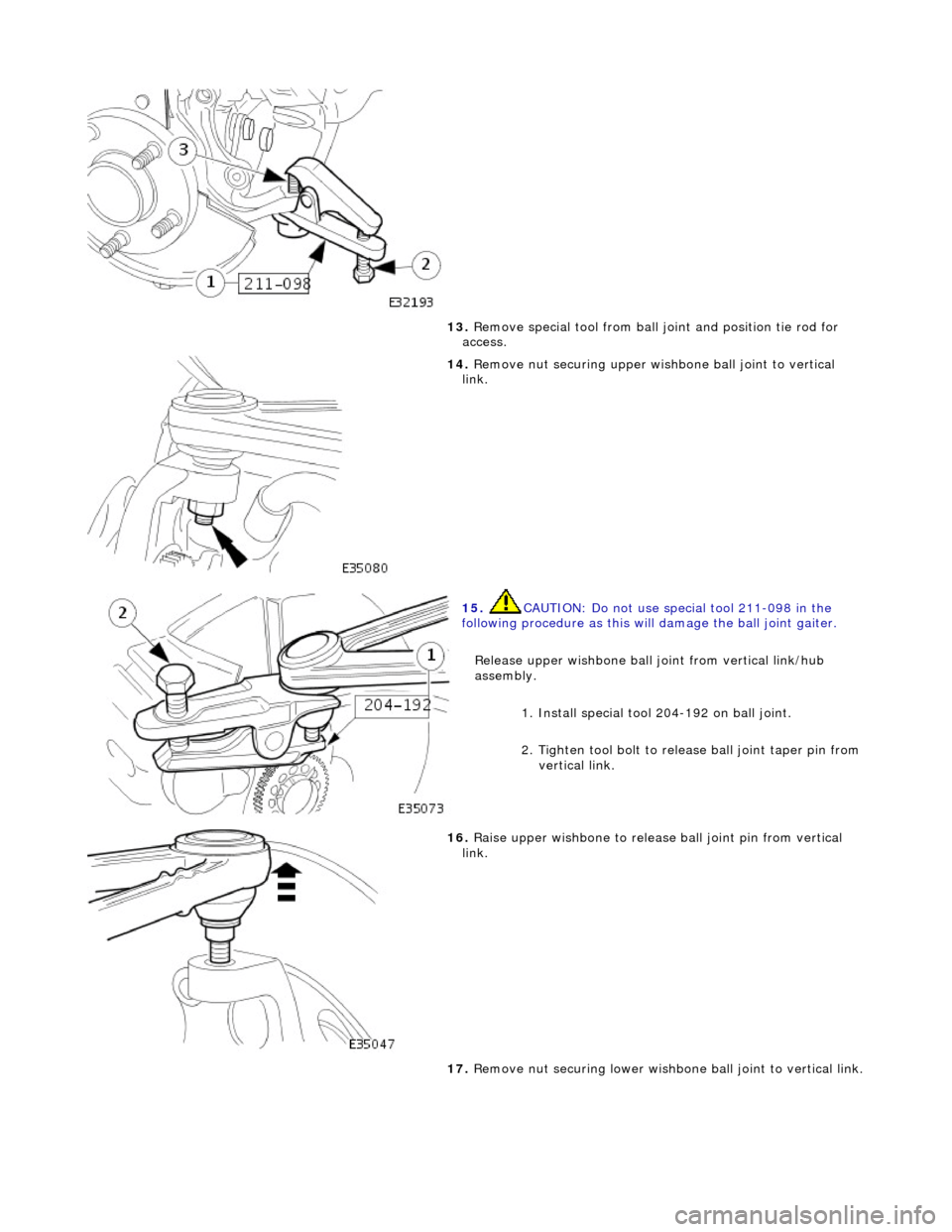
13
.
Remove special tool from ball joint and position tie rod for
access.
14
.
Remove nut securing upper wish bone ball joint to vertical
link.
15
.
CAUTION: Do not use special tool 211-098 in the
following procedure as this will damage the ball joint gaiter.
Release upper wishbone ball joint from vertical link/hub
assembly.
1. Install special tool 204-192 on ball joint.
2. Tighten tool bolt to rele ase ball joint taper pin from
vertical link.
16
.
Raise upper wishbone to release ball joint pin from vertical
link.
17. Remove nut securing lower wishbone ball joint to vertical link.
Page 156 of 2490
In
stallation
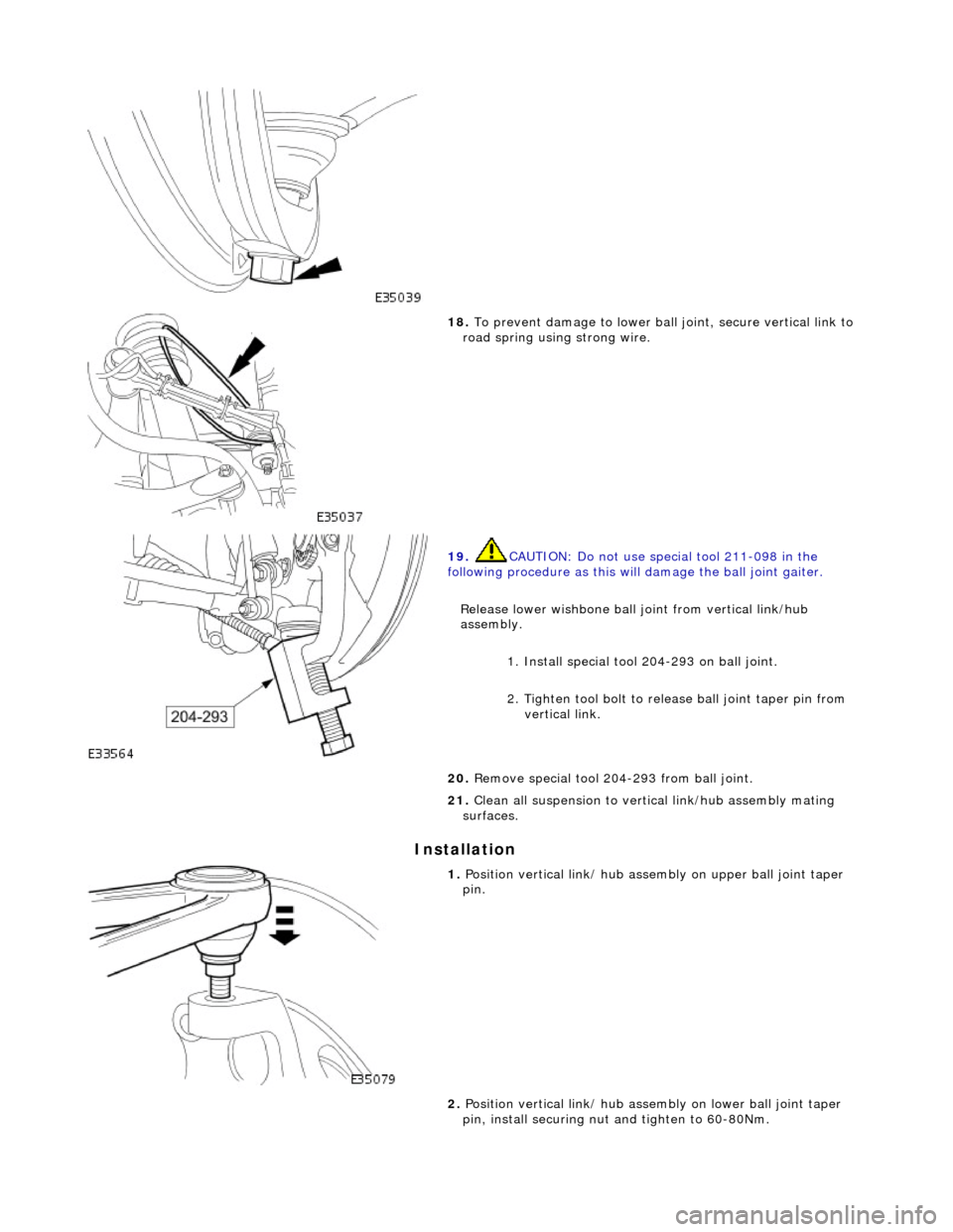
18
. To
prevent damage to lower ball
joint, secure vertical link to
road spring using strong wire.
19 . CAUTI
ON: Do not use special tool 211-098 in the
following procedure as this will damage the ball joint gaiter.
Release lower wishbone ball joint from vertical link/hub
assembly. 1. Install special tool 204-293 on ball joint.
2. Tighten tool bolt to rele ase ball joint taper pin from
vertical link.
20 .
R
emove special tool 204-293 from ball joint.
21. Clean all suspension to vertical link/hub assembly mating
surfaces.
1. Position verti c
al link/ hub asse
mbly on upper ball joint taper
pin.
2. Position vertical link/ hub asse mbly on lower ball joint taper
pin, install securing nut and tighten to 60-80Nm.
Page 158 of 2490
Re
move special tool and adaptor from spring.
9. Install road wheel. Refer to 74.20.05.
10. Raise front of vehicle, remove stands and lower vehicle.
11. Carry out steering geometry an d wheel alignment checks and
if necessary adjust. Refer to 57.65.01.


