warning JAGUAR X308 1998 2.G User Guide
[x] Cancel search | Manufacturer: JAGUAR, Model Year: 1998, Model line: X308, Model: JAGUAR X308 1998 2.GPages: 2490, PDF Size: 69.81 MB
Page 112 of 2490

Rot
ate tool adjuster to gradua
lly increase spring tension.
Pr
ogressively substitute spri
ng pan securing bolts for
guide pins.
Ti ghten spring pan
securing bolts to 70-90Nm.
6. WARNING: WHE N
ROTATING TOOL ADJUSTER, ENSURE
THAT TOOL STEM DOES NOT TU RN AND DISTURB POSITION OF
DOWEL IN SUSPENSION TURRET.
Remove Special Tool 204-111 from suspension.
Ensure spri ng
lower rubber seat
is correctly positioned and
fully seated.
R otat
e adjuster of Special Tool to release tension on
spring.
7. Ro
tate tool stem to release
dowel from turret and withdraw
tool assembly.
8. Lower vehicle to working heig ht and support on stands.
9. Install road wheel. Re fer to Section 100-02.
10. Raise vehicle, remove stands and lower vehicle onto road
wheels.
Page 115 of 2490
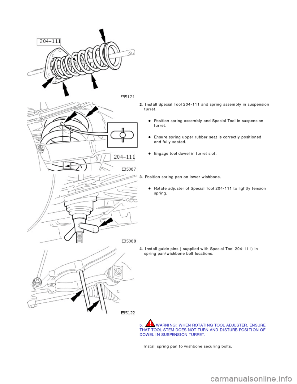
2. Ins
tall Special Tool 204-111 and spring assembly in suspension
turret.
P
osition spring assembly and Special Tool in suspension
turret.
Ensure spri
ng upper rubber se
at is correctly positioned
and fully seated.
Engage tool
dowel in turret slot.
3. Position spr
ing pan on lower wishbone.
R
otate adjuster of Special Tool 204-111 to lightly tension
spring.
4. Install guide pins ( su
pplied wi
th Special Tool 204-111) in
spring pan/wishbone bolt locations.
5. WARNING: WHEN ROTATING TOOL ADJUSTER, ENSURE
THAT TOOL STEM DOES NOT TU RN AND DISTURB POSITION OF
DOWEL IN SUSPENSION TURRET.
Install spring pan to wishbone securing bolts.
Page 116 of 2490

Align sp
ring pan with lower wishbone bolt locations.
Rot
ate tool adjuster to gradua
lly increase spring tension.
P
r
ogressively install but do no
t tighten spring pan securing
bolts.
Ti ghten spring pan
securing bolts to 70-90Nm.
Ensure spri
ng
lower rubber seat is correctly positioned in
spring pan.
6. WARNING: WHE N
ROTATING TOOL ADJUSTER, ENSURE
THAT TOOL STEM DOES NOT TU RN AND DISTURB POSITION OF
DOWEL IN SUSPENSION TURRET.
Remove Special Tool 204-111 from suspension.
Rotat
e adjuster of Special Tool to release tension on
spring.
R otate
tool stem to release dowel from turret.
With
draw tool and adaptor
.assembly.
7.
Lower vehi cle to work
ing heig
ht and support on stands.
8. Install road wheel. Re fer to Section 100-02.
9. Raise vehicle, remove stands and lower vehicle onto road
wheels.
10. Carry out steering geometry an d wheel alignment checks and
if necessary adjust. Refer to 57.65.01.
11. Carry out steering geometry an d wheel alignment checks and
if necessary adjust. Refer to 57.65.01.
Page 129 of 2490

Front Suspension - Upper Arm Bushing
Re
moval and Installation
Remov
al
CAUTI
ON: Replacement of
nuts and bolts: Various thread-locking devices are used on nuts and bolts throughout the
vehicle. These devices restrict the number of times a nut or bolt can be used. See section 100-00 for information.
S
pecial Tool(s)
Ball
Joint Taper Separator
204-192 (JD 219)
Front Camber Tie-do
wn Link
204-114 (JD 133)
1. R
aise front of vehicle.
Refer to Section 100-02.
2. P
osition camber tie down spec
ial tool 204-114 on suspension.
Fully s
lacken tool adjuster nut.
Position too
l in road spring and pass upper dowel through
slot in suspen sion turret.
3. Lower front of vehicle.
4. R
otate stem of special tool 204-114 to locate dowel in
suspension turret slot.
5. WARNING: WHEN TIGHTENING TOOL NUT, USE LOWER
DOWEL AS A GUIDE TO ENSURE THAT THE TOOL STEM DOES
NOT ROTATE AND DISTURB POSITION OF DOWEL IN
SUSPENSION TURRET.
Fully tighten nut of special tool to achieve suspension mid-laden
Page 153 of 2490
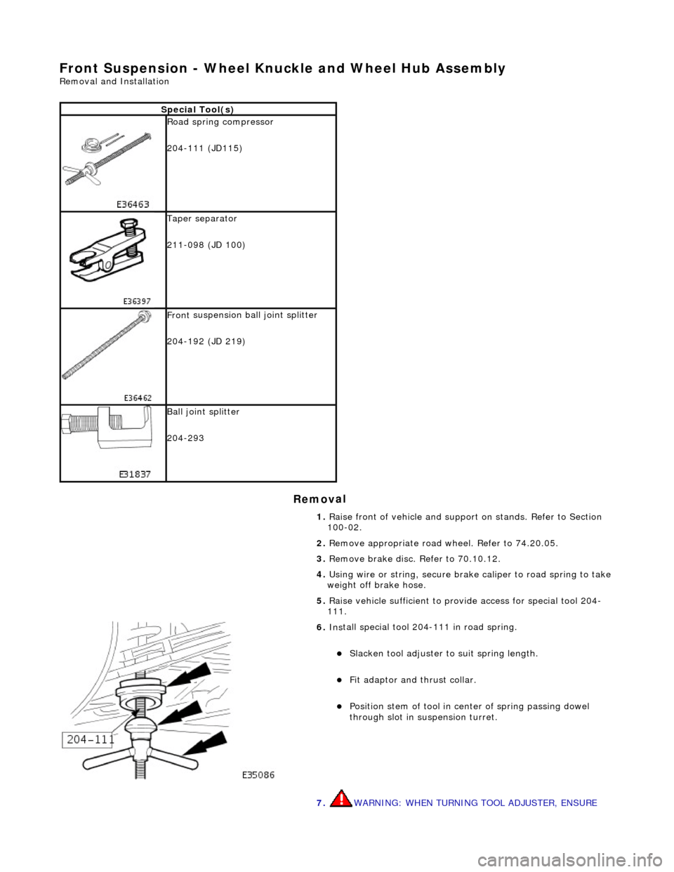
Front Susp
ension - Wheel Knuckle and Wheel Hub Assembly
Re
moval and Installation
Remov
al
S
pecial Tool(s)
R
oad spring compressor
204-111 (JD115)
Taper separator
211-098 (JD 100)
Front
suspension ball joint splitter
204-192 (JD 219)
Bal
l joint splitter
204-293
1. Raise front of vehicle and support on stands. Refer to Section
100-02.
2. Remove appropriate road wheel. Refer to 74.20.05.
3. Remove brake disc. Refer to 70.10.12.
4. Using wire or string, secure brak e caliper to road spring to take
weight off brake hose.
5. Raise vehicle sufficient to provide access for special tool 204-
111.
6. Ins
tall special tool 204-111 in road spring.
Sl
acken tool adjuster to suit spring length.
Fit adaptor and th
rust collar.
Posit
ion stem of tool in center of spring passing dowel
through slot in su spension turret.
7. WARNING: WHEN TURNING TOOL ADJUSTER, ENSURE
Page 175 of 2490
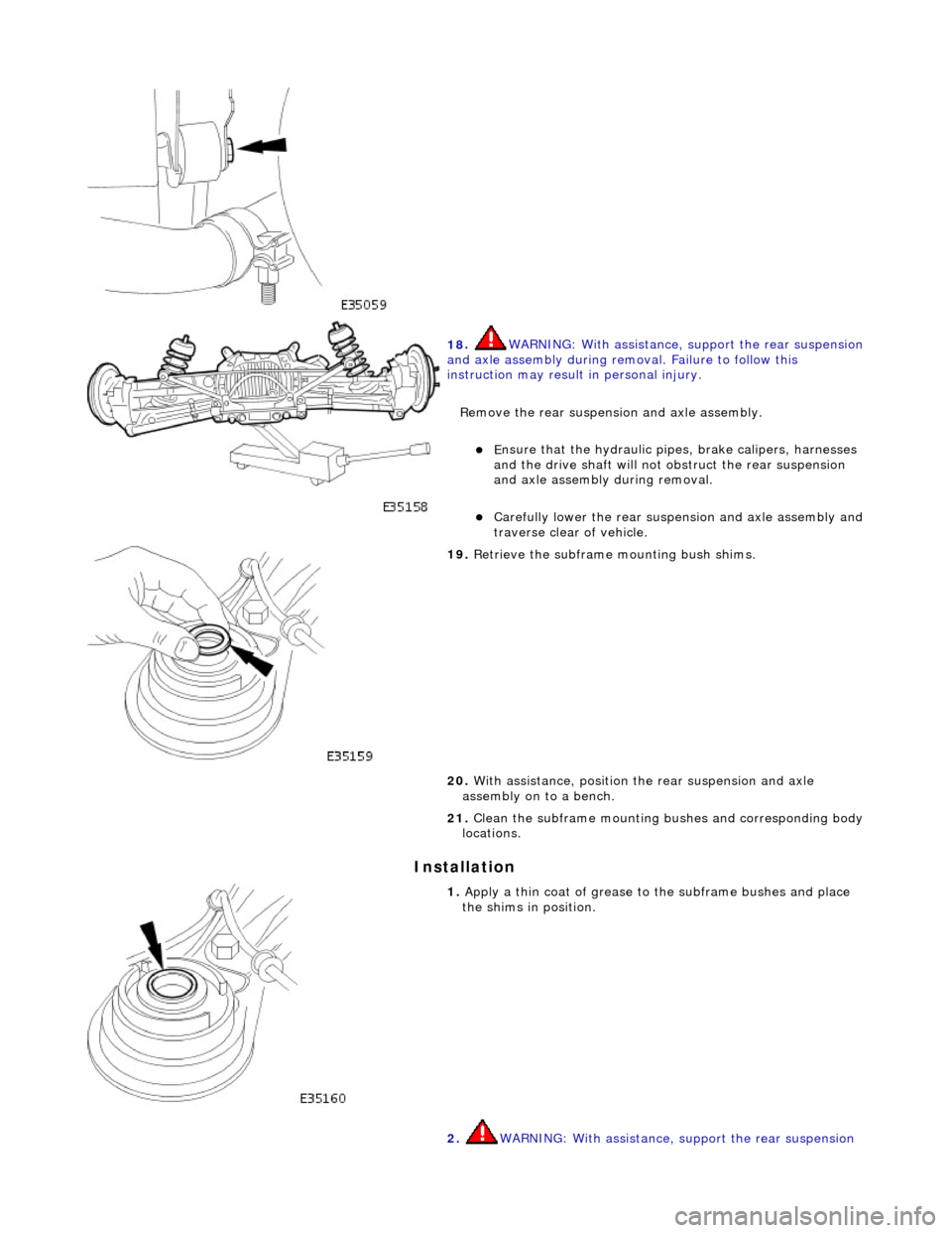
I
nstallation
18
.
WARNING: With assistance, support the rear suspension
and axle assembly during remo val. Failure to follow this
instruction may result in personal injury.
Remove the rear suspensi on and axle assembly.
E
nsure that the hydr
aulic pipes, brake calipers, harnesses
and the drive shaft will not obstruct the rear suspension
and axle assembly during removal.
Carefull
y lower the rear suspen
sion and axle assembly and
traverse clear of vehicle.
19
.
Retrieve the subframe mounting bush shims.
20. With assistance, position th e rear suspension and axle
assembly on to a bench.
21. Clean the subframe mounting bushes and corresponding body
locations.
1. Apply a th
in coat of grease to the subframe bushes and place
the shims in position.
2. WARNING: With assistance, support the rear suspension
Page 197 of 2490

With
draw the hub carrier and support on a block of wood.
9. CAUTI
ON: Note the position of
the shims during removal.
They must be returned to th eir original position during
installation.
Noting their positions, remove the shim from each end of the
pivot pin sleeve.
10
.
WARNINGS:
ENSURE THE SPECIAL TOOLS ARE POSITIONED
DIAMETRICALLY OPPOSITE ON THE SPRING AND THE ARMS ARE
CORRECTLY SEATED .
WHEN COMPRESSING THE SPRING, TIGHTEN THE
SPECIAL-TOOL ADJUSTMENT BOLTS EVENLY.
Compress the spring.
Install and alig
n the special
tools 204-179 diametrically
opposite on the spring.
Eve
nly tighten the special tool tensioning bolts to
compress the spring.
11
.
Remove the shock absorber to wishbone mounting nut and
bolt.
12. Remove the nuts securing th e shock absorber and spring
upper mounting to the body.
Page 276 of 2490
Is hard-wi
red to the instrume
nt cluster message center.
Is hard
-wired to the J1962 diagnostic connector.
Op
era
tion
Th
e
system selects the soft or
firm damper setting according to the current ro ad and driving conditions, to optimise vehicle
ride and handling.
With the vehicle stationary, the dampers are in the firm setting, but will normally switch to the soft setting when the vehicle
exceeds 8 km/h (5 mile/h); all dampers are switched simultaneously.
Sudden movement of the vehicle body, in response to road inputs, is detected by the vertical accelerometers, and the ADCM
switches the dampers to the firm setting to give improved damping of the resultant oscillations.
When cornering forces are detected by th e lateral accelerometer, the ADCM switches the dampers to the firm setting to
reduce the roll rate an d improve wheel control.
After the event has passed, the dampers revert to the soft setting.
When the footbrake is applied, the ADCM re ceives a signal and calculates the rate of vehicle deceleration. If the deceleration
rate is greater than a certain threshold, the dampers are switched to the firm setting to reduce the pitch rate and improve
wheel control.
If a system failure occurs, the ADCM grounds the output line to the instrument cluster message center, which displays a
text warning SUSPENSION FAULT and illuminates the amber warning lamp. Under fault conditions the system always fails to
the firm setting, so that the vehicle will be safe to drive un der all road and driving conditions.
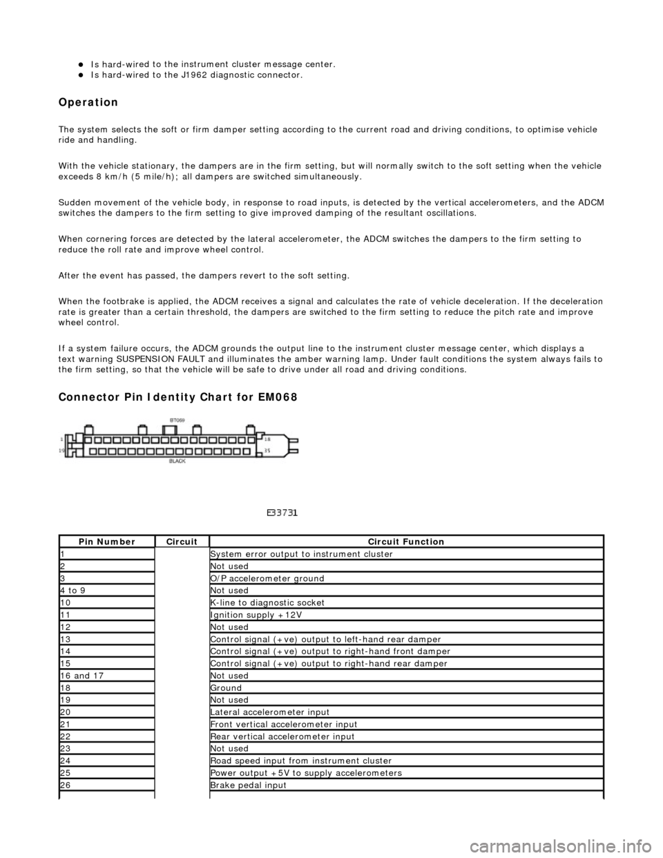
Connector Pin Identity Chart for EM068
Pin
Number
Ci
rcui
t
Circuit Functi
on
1System erro
r output to instrument
cluster
2Not
used
3O/
P a
ccelerometer ground
4 to
9
Not
used
10K-
li
ne to diagnostic socket
11Ignition su
pply +12V
12Not
used
13Control signal (+ve) output
to l
eft-hand rear damper
14Control signal (+ve) output
to right-hand front damp
er
15Control signal (+ve) output
to right-hand rear
damper
16
a
nd 17
No
t
used
18Ground
19No
t
used
20Lateral
accelerometer i
nput
21Front vertical ac
celerometer in
put
22Rear vertical
acce
lerometer input
23No
t
used
24R
o
ad speed input from
instrument cluster
25Power output +5V to suppl y accelerometers
26Brake peda
l input
Page 309 of 2490
Brake System - General Inform
ation - Brake System
D
iagnosis and Testing
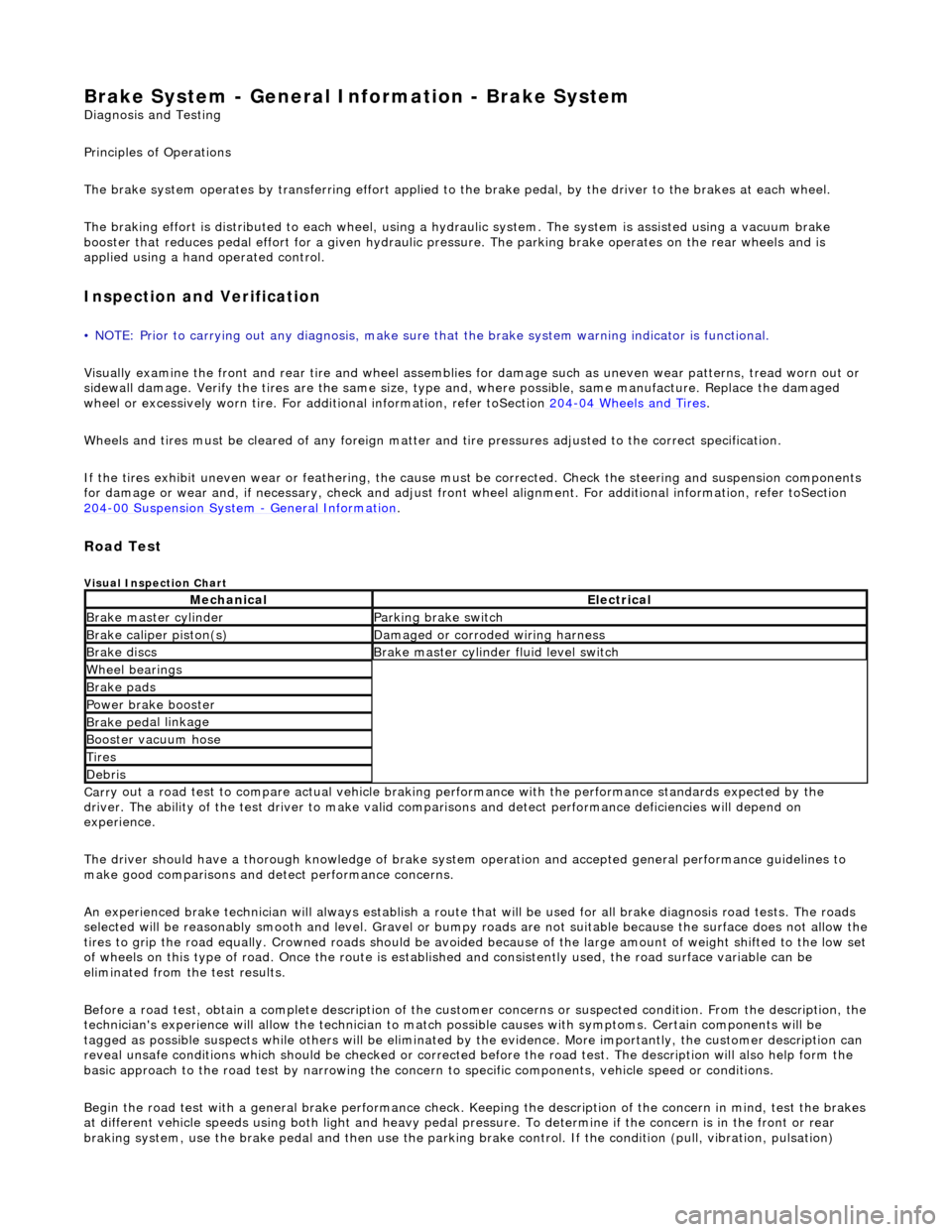
Principles of Operations
The brake system operates by transferring effort applied to th e brake pedal, by the driver to the brakes at each wheel.
The braking effort is distributed to each wheel, using a hydraulic system. The system is assisted using a vacuum brake
booster that reduces pedal effort for a given hydraulic pressure. The parking brake operates on the rear wheels and is
applied using a hand operated control.
I
nspection and Verification
•
NOTE: Prior to carrying out any diagno
sis, make sure that the brake system warning indicator is functional.
Visually examine the front and rear tire and wheel assemblies for damage such as un even wear patterns, tread worn out or
sidewall damage. Verify the tires are th e same size, type and, where possible, same manufacture. Replace the damaged
wheel or excessively worn tire. For a dditional information, refer toSection 204
-0
4 Wheels and Tires
.
W
heels and tires must be cleared of an
y foreign matter and tire pressures ad justed to the correct specification.
If the tires exhibit uneven wear or feathering, the cause must be corrected. Check the steering and suspension components
for damage or wear and, if ne cessary, check and adjust front wheel alignment. For additional information, refer toSection
204
-00 Suspen
sion System
- General Informati
on
.
Road Test
V
isual Inspection Chart
Carr
y out a road test to compare actual vehicle braking performance with the
performance standards expected by the
driver. The ability of the test driver to make valid compar isons and detect performance deficiencies will depend on
experience.
The driver should have a thorough knowledge of brake system operation and accepted general performance guidelines to
make good comparisons and de tect performance concerns.
An experienced brake technician will always establish a route that will be used for all br ake diagnosis road tests. The roads
selected will be reasonably smooth and level. Gravel or bump y roads are not suitable because the surface does not allow the
tires to grip the road equally. Crowned roads should be avoide d because of the large amount of weight shifted to the low set
of wheels on this type of road. Once th e route is established and consistently used, the road surface variable can be
eliminated from the test results.
Before a road test, obtain a complete description of the customer concerns or suspec ted condition. From the description, the
technician's experience will allow the te chnician to match possible causes with symptoms. Certain components will be
tagged as possible suspects while others wi ll be eliminated by the evidence. More importantly, the customer description can
reveal unsafe conditions which should be ch ecked or corrected before the road test. The description will also help form the
basic approach to the road test by narrowing the concern to specific components, vehicle speed or conditions.
Begin the road test with a general brake performance check. Keeping the description of the concern in mind, test the brakes
at different vehicle speeds using both ligh t and heavy pedal pressure. To determine if the concern is in the front or rear
braking system, use the brake pe dal and then use the parking brake control. If the condition (pull, vibration, pulsation)
MechanicalElectrical
Brake m
aster cylinder
Parkin
g brake switch
Brake ca
liper piston(s)
D
amaged or corroded wiring harness
Brake di
scs
B
rake master cylinder fluid level switch
Wh
eel bearin
gs
Brake pads
Power brake booster
Brake ped
al linkage
Boost
er vacuum hose
Tire
s
De
bris
Page 310 of 2490
oc
curs only with the parking brake, th
e concern is in the rear brake system.
If the concern becomes evident during this check, verify it fits the description given before the road test. If the concern is
not evident, attempt to duplicate the condition using the information from the description.
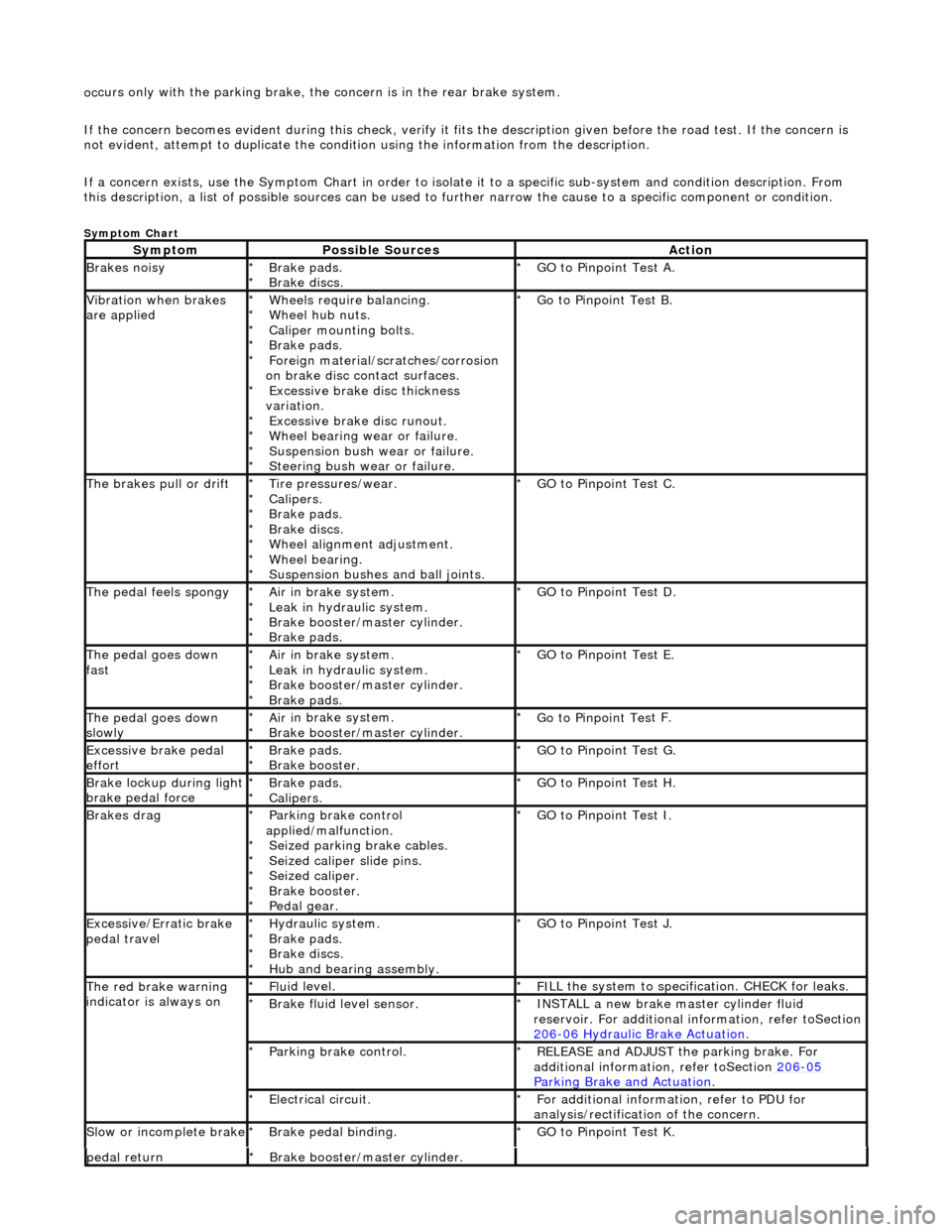
If a concern exists, use the Symptom Chart in order to isolate it to a specific sub-system and condition description. From
this description, a list of possible sources can be used to further narrow the cause to a specific component or condition.
Sym
ptom Chart
Sy
m
ptom
Possib
l
e Sources
Acti
o
n
Brakes
n
oisy
Brake pads.
Brake di
scs
.
*
*
GO to Pinpoint
Tes
t A.
*
Vibration wh
en brakes
are applied
Wh eels require bala
ncing.
Wheel hub nuts.
Caliper mounting bolts.
Brake pads.
Foreign material/scr atches/corrosion
on brake disc contact surfaces. Excessive brake disc thickness
variation. Excessive brake disc runout.
Wheel bearing wear or failure.
Suspension bush wear or failure.
Steering bush wear or failure.
*
*
*
*
*
*
*
*
*
*
Go to Pinpoint
Tes
t B.
*
The brakes pull or drif tTire pressures/wear.
Calipers.
Brake pads.
Brake di
scs.
Wheel alignment adjustment.
Wheel bearing.
Suspension bushes and ball joints.
*
*
*
*
*
*
*
GO to Pinpoint
Tes
t C.
*
The pedal feels spongyAir i
n brake system.
Leak in hydraulic system.
Brake booster/master cylinder.
Brake pads.
*
*
*
*
GO to Pinpoint Tes
t D.
*
The pedal goes down
fa s
t
Ai
r i
n brake system.
Leak in hydraulic system.
Brake booster/master cylinder.
Brake pads.
*
*
*
*
GO to Pinpoint
Tes
t E.
*
The pedal goes down
slowl yAir i
n brake system.
Brake booster/master cylinder.
*
*
Go to Pinpoint
Tes
t F.
*
Excessive brake pedal
effor tBrake pads.
Brake booster.
*
*GO to Pinpoint
Tes
t G.
*
Brake lockup du ring ligh
t
brake pedal force
Brake pads.
Calipers.
*
*GO to Pinpoint
Tes
t H.
*
Brakes d r
ag
Parkin
g brake con
trol
applied/malfunction. Seized parking brake cables.
Seized caliper slide pins.
Seized caliper.
Brake booster.
Pedal gear.
*
*
*
*
*
*
GO to Pinpoint
Tes
t I.
*
Exce ssi
ve/Erratic brake
pedal travel
Hydrau li
c system.
Brake pads.
Brake discs.
Hub and bearing assembly.
*
*
*
*
GO to Pinpoint
Tes
t J.
*
The red brak e warning
indi
cator is always on
Fl
ui
d level.
*
F I
LL the system to specification. CHECK for leaks.
*
Brake flu i
d level sensor.
*
I N
STALL a new brake master cylinder fluid
reservoir. For additional in formation, refer toSection
206
-0 6
Hydraulic Brake Actuation
.
*
Parkin
g brake con
trol.
*
REL
E
ASE and ADJUST the parking brake. For
additional information, refer toSection 206
-05
Parkin g Brake an
d Actuation
.
*
E
l
ectrical circuit.
*
F or additional
information, refer to PDU for
analysis/rectification of the concern.
*
Sl
ow or i
ncomplete brake
Brake peda
l binding.
*
GO to Pinpoint Tes
t K.
*
pedal retu rnBr
ake booster/master cylinder.
*