warning JAGUAR X308 1998 2.G Repair Manual
[x] Cancel search | Manufacturer: JAGUAR, Model Year: 1998, Model line: X308, Model: JAGUAR X308 1998 2.GPages: 2490, PDF Size: 69.81 MB
Page 473 of 2490

6. NO
TE: The suitable funnel should have the a capacity of 4
litres and O-ring seal
• NOTE: The suitable funnel must be tightly sealed to the
power steering fluid reservoi r to avoid fluid leakage.
Install a suitable funnel onto the power steering fluid
reservoir.
7. WARNING: Do not work on or under a vehicle supported
only by a jack. Always support the vehicle on safety stands.
Raise and support the vehicle with the wheels just clear of the
ground.
8. CAUTI
ONS:
Steps 8 and 9 must be carried out within 2 - 3 seconds of
each other. Failure to follow this instruction may result in damage
to the power steering system.
Be prepared to collect escaping fluids.
Using the suitable funnel, top up the power steering system
with the specified fluid. Make su re the fluid level is maintained
at two thirds full in the funnel.
9. CAUTI
ONS:
Be prepared to collect escaping fluids.
Page 490 of 2490
Power Steering - Power Steering
Diagn
osis and Testing
Refer to the Description and Operation sub-section for details of the power operated steering system and Servotronic control
system.
Power Steer ing Pressure Test
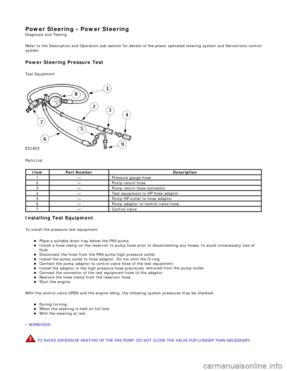
Test Equ
i
pment
Parts List
In
stalling Test Equipment
To
in
stall the pressure test equipment:
Pla
c
e a suitable drain tray below the PAS pump.
Install a hose clamp
on
the re
servoir to pump hose prior to disconnecting any hoses, to avoid unnecessary loss of
fluid.
Di sc
onnect the hose from the PAS pump high pres
sure outlet.
Ins
tall the pump outlet to hose ad
aptor. Do not omit the O-ring.
Conn
ect the pump adaptor to control valve hose of the test equipment.
Install th
e adaptor in the high pressure hose previ
ously re
moved from the pump outlet.
Conne
ct the connector of the test equipment hose to the adaptor.
R
e
move the hose clamp fro
m the reservoir hose.
Start th
e engine.
With the control valve OPEN and the engine idling , the following system pressures may be checked:
Du
ring turning.
W
h
en the steering is
held on full lock.
With
the steeri
ng at rest.
• WARNINGS:
TO AVOID EXCESSIVE HEATING OF THE PAS PUMP, DO NOT CLOSE THE VALVE FOR LONGER THAN NECESSARY.
Ite
m
Par
t
Number
De
scr
iption
1—Pressure
gauge hose
2—Pump return hose
3—Pump return hose connector
4—Test equi
pment to
HP hose adaptor
5—Pump HP outlet to hose adaptor
6—Pump adaptor
to control valve hose
7—Control valve
Page 512 of 2490
In
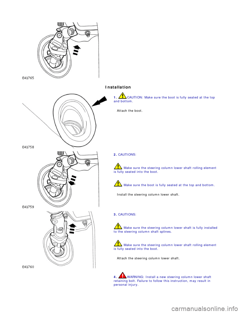
stallation
1.
CAUTIO
N: Make sure the boot
is fully seated at the top
and bottom.
Attach the boot.
2. CAUTI O
NS:
Make sure the steering column lower shaft rolling element
is fully seated into the boot.
Make sure the boot is fully seated at the top and bottom.
Install the steering column lower shaft.
3. CAUTI O
NS:
Make sure the steering column lower shaft is fully installed
to the steering column shaft splines.
Make sure the steering column lower shaft rolling element
is fully seated into the boot.
Attach the steering column lower shaft.
4. WARNING: In stall a new stee ring column lower shaft
r
etaining bolt. Failure to follow this instruction, may result in
personal injury.
Page 513 of 2490

CAUTI
ON: Make sure the steering
column lower shaft is fully
installed on the steering column shaft splines.
Install the steering column lower shaft retaining bolt.
Ti
ghten to 28 - 34 Nm.
5.
R
aise the vehicle.
6. WARNING: In
stall a new stee
ring column lower shaft
retaining bolt. Failure to follow this instruction, may result in
personal injury.
Attach the steering column lower shaft. 1. Attach the steering column lower shaft.
2. Install the steering column lower shaft retaining bolt.
1. Tighten to 28 - 34 Nm
.
3
. Tighten to 28 - 34 Nm.
Page 516 of 2490
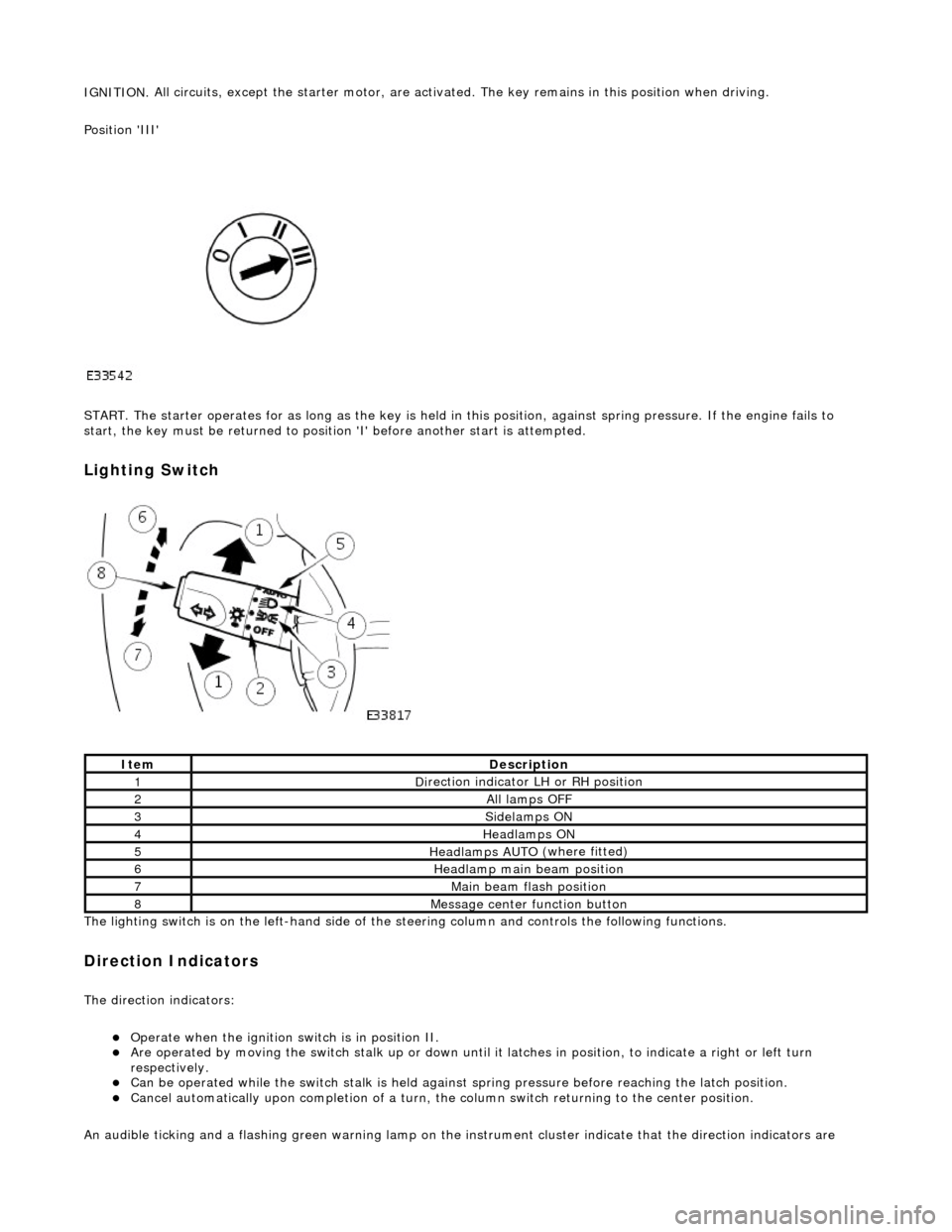
IGNITION.
All circuits, except the star
ter motor, are activated. The key rema ins in this position when driving.
Position 'III'
START. The starter operates for as long as the key is held in this position, ag ainst spring pressure. If the engine fails to
start, the key must be returned to position 'I' befo re another start is attempted.
Lighting Switch
The li
ghting switch is on the left-h
and side of the steering column and controls the following functions.
Direction Indicators
The direction in
dicators:
Operate
when the ignition switch is in position II.
Are operat
ed by movi
ng the switch stalk up or down until it latches in position, to in
dicate a right or left turn
respectively.
Can be o p
erated while the switch stalk is held against
spring pressure before reaching the latch position.
Cancel
automatically upon completion of a turn, the
column switch returning to the center position.
An audible ticking and a flashing green warning lamp on the in strument cluster indicate that the direction indicators are
Ite
m
De
scr
iption
1D
i
rection indicator LH or RH position
2All lamps OFF
3Side
lamps ON
4Headlamps ON
5Headlamps AUT O
(where fitted)
6He
adlam
p main beam position
7Mai
n
beam flash position
8M
e
ssage center function button
Page 517 of 2490
o
perating. If an indicator bulb fails, the warning
lamp and ticking operate at twice the normal rate.
Sidelam
ps and Headlamps
Thes
e are controlled by rotating the end of the column switch as follows.
In the OFF position:
All
exterior lamps are switched OFF.
In the sidelamp position:
The front
sidelamps, tail, license plate and any other la
mps required by local legislation are switched ON.
The
sidelamps tell-tale lamp illuminates.
In the headlamp position, with the ignition switch in position II:
The h
eadlamps are switched ON in addition to the lamps switched on in the sidelamp position.
If the ignition is switched to the OFF position with the column switch in the headlamp position, the sidelamps, tail and
license plate lamps will stay ON, but the headlamps will switch OFF.
In the AUTO position (where fitted), with the ignition switch in position II:
Th
e sensor mounted on the back of the interior rear view
mirror monitors exterior light levels and automatically
switches the sidelamps and di pped headlamps ON and OFF.
The sensitivity level can be adjusted by turn ing the sensor control knob on the back of the interior mirror, left to decrease or
right to increase. The sensor must not be covered and the windscreen must be kept clean.
Headlamp Main Bea
m Position
Wi
th the column switch in
the headlamp position:
Movin
g the switch stalk away fro
m the steering wheel switches the headlamps to main beam.
Movin
g the switch stalk towards the steering wheel switches the headlamps to dipped beam.
The main beam tell-tale lamp illuminates when the headlamps are switched to main beam.
Ma
in Beam Flash
Wi
th the ignition switch and column switch in any position:
Pulling the
switch stalk agains
t spring pressure towards th e steering wheel illuminates the headlamps on main beam
for as long as the switch is held.
The main beam tell-tale lamp illuminates while the headlamps are illuminated.
M
essage Center Functions
T
he message center functions:
Are se
lected by the button located at the end of the lighting switch stalk.
Are se
lected in turn, by repeatedly pressing the button,
from the odometer reading, through the trip computer data
in sequence, and back to th e odometer reading again.
Page 550 of 2490
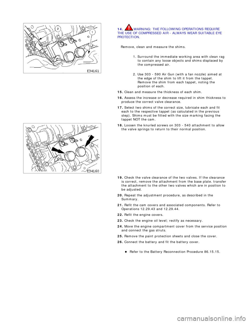
14
. WARNING: TH
E FOLLOWING OPERATIONS REQUIRE
THE USE OF COMPRESSED AIR - ALWAYS WEAR SUITABLE EYE
PROTECTION.
Remove, clean and measure the shims.
1. Surround the immediate wo rking area with clean rag
to contain any loose objects and shims displaced by
the compressed air.
2. Use 303 - 590 Air Gun (with a fan nozzle) aimed at the edge of the shim to lift it from the tappet.
Remove the shim from each tappet, noting the
position of each.
15 . Cl
ean and measure the thickness of each shim.
16. Assess the increase or decrease required in shim thickness to
produce the correct valve clearance.
17. Select two shims of the correct size, lubricate each and fit
each to the respective tappet (as calculated in the previous
step). Shims must be fitted with the size marking facing the
tappet NOT the cam.
18 . Loos
en the knurled screws on 303 - 540 attachment to allow
the valve springs to return to their normal position.
19. Check the valve clearance of the two valves. If the clearance
is correct, remove the attachment from the base plate. transfer
the attachment to the other two valves which are in position to
be adjusted.
20. Repeat the adjustment procedure, as described in the
Summary.
21. Refit the cam covers and associated components. Refer to
Operations 12.29.43 and 12.29.44.
22. Refit the engine covers.
23. Check the engine oil level; rectify as necessary.
24. Move the engine compartment cover from the service position
and connect the gas struts.
25. Remove the paint protection sheets and close the cover.
26. Connect the battery and fit the battery cover.
Refe
r to the Battery Reconnection Procedure 86.15.15.
Page 704 of 2490
Engine - Intake Manifol
d
In-v
ehic
le Repair
Remov
a
l
W
A
RNING: BEFORE PROCEEDING, IT IS ESSENTIAL THAT
THE WARNINGS GIVEN IN SECTION 100-00 (UNDER THE
HEADING 'SAFETY PRECAUTIONS') ARE READ AND UNDERSTOOD.
S p
ecial Tool(s)
Qu
ic
k Fit Connector Release Tool
310-044
Qu ic
k Fit Connector Release Tool
310-054
Inject or Remov
al Tools
303-539
F u
el Injection Pressu
re Test Equipment
310-058
1. Open the engine compartment and fit paintwork protection
sheets.
2. Carefully remove the en gine covers, taking care not to damage
the plastic fixings or the rubber inserts.
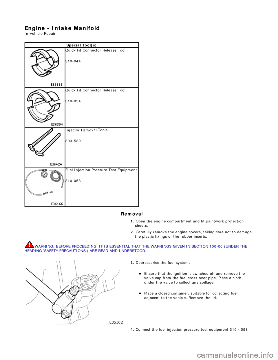
3. Depress
urise the fuel system.
E
n
sure that the ignition is
switched off and remove the
valve cap from the fuel cross-over pipe. Place a cloth
under the valve to collect any spillage.
Pla c
e a closed container, su
itable for collecting fuel,
adjacent to the vehicle. Remove the lid.
4. Connect the fuel injection pres sure test equipment 310 - 058
Page 718 of 2490
Engine - Intake Manifold Gaskets
In-vehicle Repair
Removal
WARNING: BEFORE PROCEEDING, IT IS ESSENTIAL THAT THE WARNINGS GIVEN IN SECTION 100-00 (UNDER THE
HEADING 'SAFETY PRECAUTIONS') ARE READ AND UNDERSTOOD.
Special Tool(s)
Quick Fit Connector Release Tool
310-044
Quick Fit Connector Release Tool
310-054
Fuel Injection Pressu re Test Equipment
310-058
1. Open the engine compartment and fit paintwork protection
sheets.
2. Carefully remove the en gine covers, taking care not to damage
the plastic fixings or the rubber inserts.
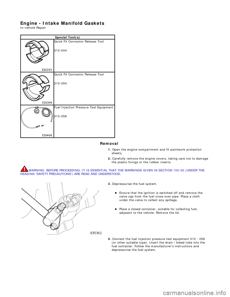
3. Depressurise the fuel system.
Ensure that the ignition is switched off and remove the
valve cap from the fuel cross-over pipe. Place a cloth
under the valve to collect any spillage.
Place a closed container, su itable for collecting fuel,
adjacent to the vehicle. Remove the lid.
4. Connect the fuel injection pres sure test equipment 310 - 058
(or other suitable type). Insert the drain / bleed tube into the
fuel container. Follow the ma nufacturer's instructions and
depressurise the fuel system.
Page 729 of 2490
Engine - Intake Manifold LH
In-vehicle Repair
Removal
WARNING: BEFORE PROCEEDING, IT IS ESSENTIAL THAT THE WARNINGS GIVEN IN SECTION 100-00 (UNDER THE
HEADING 'SAFETY PRECAUTIONS') ARE READ AND UNDERSTOOD. 1.
Open the engine compartment and fit paintwork protection
sheets.
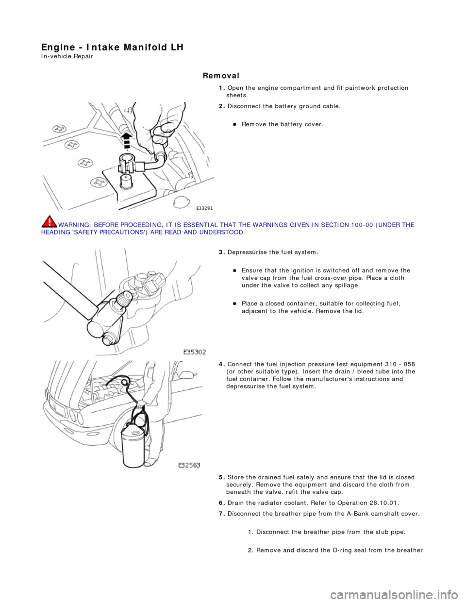
2. Disconnect the batt ery ground cable.
Remove the battery cover.
3. Depressurise the fuel system.
Ensure that the ignition is switched off and remove the
valve cap from the fuel cross-over pipe. Place a cloth
under the valve to collect any spillage.
Place a closed container, su itable for collecting fuel,
adjacent to the vehicle. Remove the lid.
4. Connect the fuel injection pres sure test equipment 310 - 058
(or other suitable type). Insert the drain / bleed tube into the
fuel container. Follow the ma nufacturer's instructions and
depressurise the fuel system.
5. Store the drained fuel safely and ensure that the lid is closed
securely. Remove the equipmen t and discard the cloth from
beneath the valve. refit the valve cap.
6. Drain the radiator coolant. Refer to Operation 26.10.01.
7. Disconnect the breather pipe fro m the A-Bank camshaft cover.
1. Disconnect the breather pipe from the stub pipe.
2. Remove and discard the O-ring seal from the breather