warning JAGUAR X308 1998 2.G Service Manual
[x] Cancel search | Manufacturer: JAGUAR, Model Year: 1998, Model line: X308, Model: JAGUAR X308 1998 2.GPages: 2490, PDF Size: 69.81 MB
Page 397 of 2490

I
nstallation
Re
move bolts.
R
emove lever.
10
.
Remove gasket.
11
.
Remove warning-light switch from lever.
R
emove screws.
Re
move switch.
1. Inst
all warning-light switch to hand lever.
Install and tigh
ten
screws to 3 Nm.
2. Install gasket to handbrake lever.
Page 401 of 2490

I
nstallation
1
. Remove upper return spring.
2. Remove lower return spring.
9. Remove brake dust and clean components, see WARNING
above.
10. Repeat procedure to remove pa rking brake shoes on opposite
side of vehicle.
1. I
nstall brake shoes to vehicle.
Install brake shoes to parkin
g brake lever-me
chanism in
the arrangement shown.
2. N
OTE: Make sure retaining pin is seated correctly in backing
plate.
Install rear shoe retaining pin.
Align hu
b access hole.
Inst
all retaining pin.
3. Inst
all adjuster assembly.
Lubricate adjuster
mechanism
with appropriate grease.
Move
front shoe forwards.
Inst
all adjuster assembly.
4. NOTE: Make sure retaining pin is seated correctly in backing
Page 406 of 2490
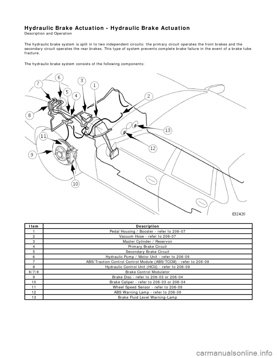
Hydraulic Br
ake Actuation -
Hydraulic Brake Actuation
Description and Operation
The hydraulic brake system is split in to two independent circuits: the primary ci rcuit operates the front brakes and the
secondary circuit operates the re ar brakes. This type of system prevents comple te brake failure in the event of a brake tube
fracture.
The hydraulic brake system consists of the following components:
Ite
m
Descr
iption
1Pedal Housi
ng / Booster - refer to 206-07
2Vacu
um Hose - refer to 206-07
3Mast
er Cyl
inder / Reservoir
4Primary Brake Circu
i
t
5Secon
dary Brake Circuit
6Hydrauli c
Pump / Motor Unit - refer to 206-09
7ABS/Traction
Control Control Modu
le (ABS/TCCM) - refer to 206-09
8Hydraulic Cont
rol Unit (HCU) - refer to 206-09
6/
7/
8
Br
ak
e Control Modulator
9Brake
Di
sc - refer to 206-03 or 206-04
10Brake
Cali
per - refer to 206-03 or 206-04
11W
h
eel Speed Sensor - refer to 206-09
12ABS Warning Lamp -
refer to 206
-09
13Brake F
l
uid Level Warning-Lamp
Page 407 of 2490

The t
andem master cylinder contains two in
dependent pistons, fluid pressure to each brake circuit is controlled by its own
individual piston. Brake fluid is supplied to the master cylinder by the reservoir, which is divided into two sections to preve nt
total fluid loss should one of the circuits fail. A port situated at the bottom of each section of the reservoir supplies the f luid
to each piston.
The fluid reservoir has a fluid-le vel indicator switch installed, which operates when the fluid level is low, causing the brake
fluid level warning-lamp to illuminate.
Bra
ke Caliper
The brake
calipers are of the single piston
type. The caliper carrier, which is secured to the vertical link by two bolts, carr ies
the single-piston caliper housing. The cali per housing is secured to the caliper carrier by two guide-pins and an anti-rattle
spring. When the brakes are applied, the caliper-housing piston pushes the brake pad in front of it, to wards the brake disc.
This movement forces the calipe r housing to move along the guid e-pins, in the opposite direction of the piston, to apply the
second brake pad.
Br
embo Brake Caliper
The four
cylinder brake caliper is rigidly attached to the vert
ical link via an anchor bracket. The caliper is a split assembly
with each side of the caliper, housing two pistons. The two-pairs of opposed pistons act direct ly on the brake pads mounted
one each side of the disc.
Mast
er Cylinder and Reservoir
Page 415 of 2490
2
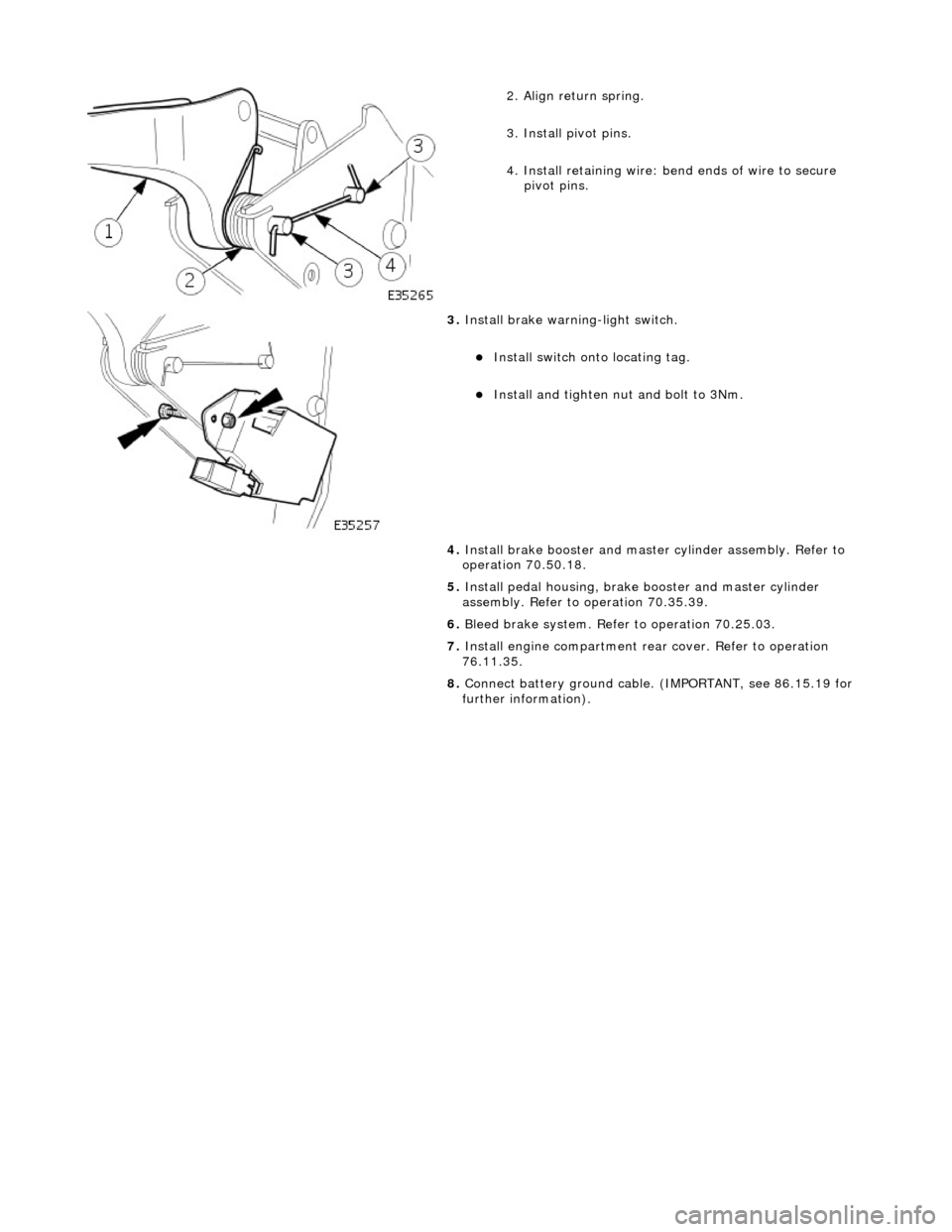
. Align return spring.
3. Install pivot pins.
4. Install retaining wire: bend ends of wire to secure
pivot pins.
3. Inst
all brake warning-light switch.
Inst
all switch onto locating tag.
Install and tigh
ten nut and bolt to 3Nm.
4. Install brake booster and master cylinder assembly. Refer to
operation 70.50.18.
5. Install pedal housing, brake booster and master cylinder
assembly. Refer to operation 70.35.39.
6. Bleed brake system. Refer to operation 70.25.03.
7. Install engine compartment rear cover. Refer to operation
76.11.35.
8. Connect battery ground cable. (IMPORTANT, see 86.15.19 for
further information).
Page 416 of 2490
Hydrau
lic Brake Actuation - Brake Pedal and Bracket, Brake Booster and
Brake Master Cylinder
Re mo
val and Installation
Remova
l
• C
A
UTIONS:
Replacement of nuts and bolts: Various thread-locking de vices are used on nuts and bolts throughout the vehicle.
These devices restrict the number of times a nut or bolt can be used. See section 100-00 for information.
Remove brake fluid spilla ge immediately from paint work, with clean water.
1. Position vehi cl
e on a four-post lift.
2. Open engine compartment and fit paint work protection covers
to fenders.
3. Disconnect battery ground cable (IMPORTANT, refer to
operation 86.15.19 for fu rther information).
4. Remove engine compartment rear cover. Refer to operation
76.11.35.
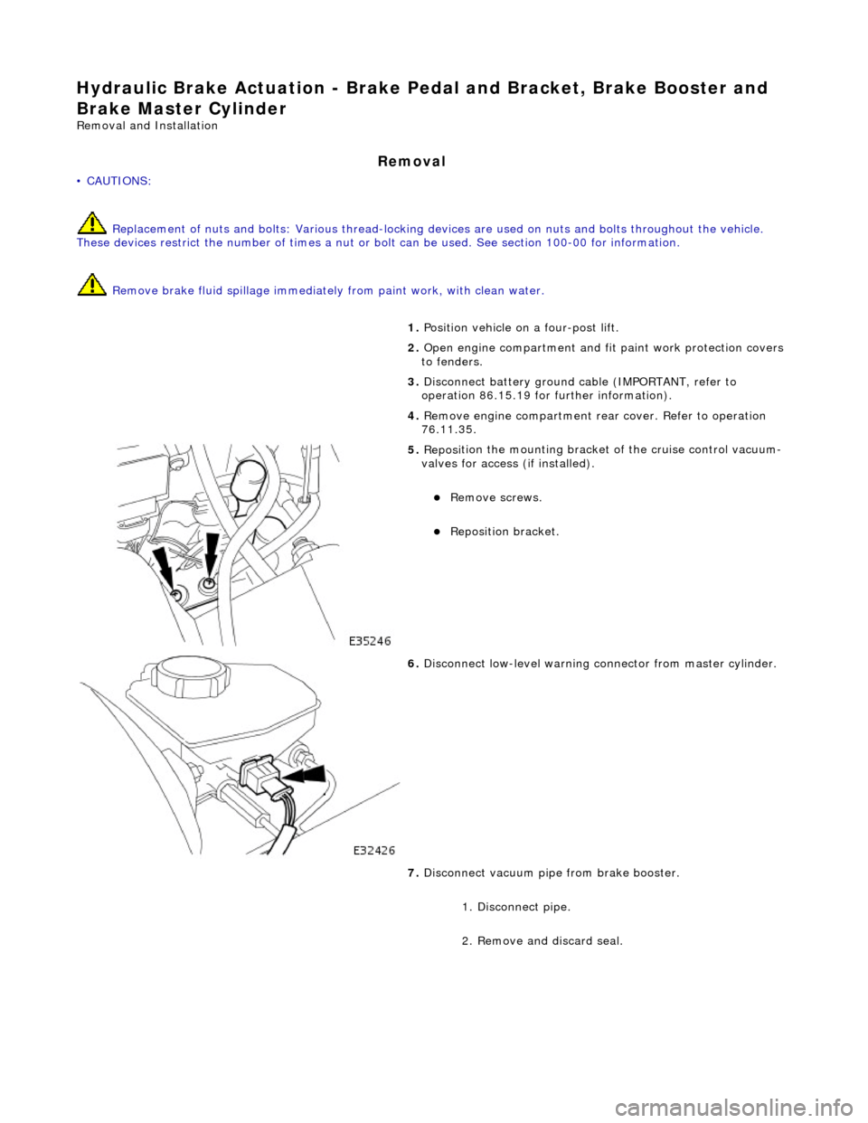
5. Reposi
tion the mounting bracket of the cruise control vacuum-
valves for access (if installed).
R e
move screws.
Reposition bracket.
6. Disc
onnect low-level warning connector from master cylinder.
7. Disconnect vacuum pipe from brake booster.
1. Disconnect pipe.
2. Remove and discard seal.
Page 420 of 2490
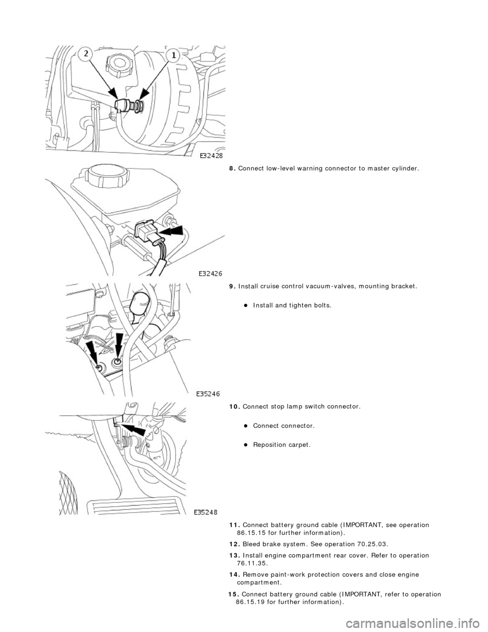
8. Conne ct
low-level warning connector to master cylinder.
9. Inst al
l cruise control vacuum-valves, mounting bracket.
Install and tigh
ten bolts.
10 . Conne
ct stop lamp switch connector.
Conne
ct
connector.
Re
posi
tion carpet.
11. Connect battery ground cable (IMPORTANT, see operation
86.15.15 for further information).
12. Bleed brake system. See operation 70.25.03.
13. Install engine compartment rear cover. Refer to operation
76.11.35.
14. Remove paint-work protection covers and close engine
compartment.
15 . Conne
ct battery ground cable (I
MPORTANT, refer to operation
86.15.19 for further information).
Page 430 of 2490
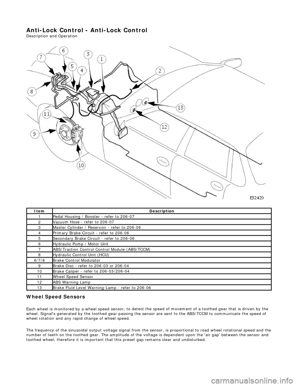
Anti-Lock Control - Anti-Lock Control
Description and Operation
Wheel Spe
ed Sensors
Each
wheel is monitored by a wheel speed se n
sor, to detect the speed of movement of
a toothed gear that is driven by the
wheel. Signal's generate d by the toothed gear passing th e sensor are sent to the ABS/TCCM to communicate the speed of
wheel rotation and any rapid change of wheel speed.
The frequency of the sinusoidal output voltag e signal from the sensor, is proportional to road wheel rotational speed and the
number of teeth on the toothed gear. The amplitude of the volt age is dependent upon the 'air gap' between the sensor and
toothed wheel, therefore it is important that this preset gap remains clear and undisturbed.
Ite
m
De
scr
iption
1Pe
dal Housi
ng / Booster - refer to 206-07
2Vac
u
um Hose - refer to 206-07
3Mas
t
er Cylinder / Reservoir - refer to 206-06
4Pri
m
ary Brake Circuit - refer to 206-06
5Sec
ondary Brake Circuit - refer to 206-06
6Hydraulic
Pump / Motor Unit
7ABS/Traction
Control Control Module (ABS/TCCM)
8Hydraulic Cont
rol Unit (HCU)
6/
7/
8
Br
ak
e Control Modulator
9Brake
Di
sc - refer to 206-03 or 206-04
10Brake
Cali
per - refer to 206-03/206-04
11Wh
ee
l Speed Sensor
12ABS Warning Lamp
13Brake
Fl
uid Level Warning-Lamp - refer to 206-06
Page 432 of 2490
It is a reciprocating two
-circuit pu
mp in which one brake circuit is as signed to each pump circuit.
It supplies th
e fluid pressure and vo
lume to supply the brake circuits under ABS and Traction control.
The pump is driven by an electri
c motor, with the pump
housing incorporating two lo w pressure accumulators and
damping chambers for each brake circuit.
The ac cu
mulator stores the pressure and smooths out the output pu
lses from the pump.
ABS Warning Lamp
The sys
tem will be set in a fail-safe mode if a problem is de
tected; a warning lamp on the instrument panel will notify the
driver there is a problem.
Anti-Lock Braking Sy
stem (ABS)
The AB
S components are combined with
an hydraulic booster and a tandem master cylinder to provide a two circuit braking
system. The system comprises, four wheel speed sensor s, a brake control modulator and an ABS warning lamp.
Should a wheel start to lock-up during braking a signal tr ansmitted from the wheel speed sensor to the brake control
modulator will start the hydraulic pump. The brake control modula tor will close the input valve of the line connected to the
locked-wheel to stop any increase in fluid pressure to the br ake caliper. If this fails to prevent the wheel locking, the
pressure in the caliper will be decreased by opening the return valve until th e wheel starts accelerating again. The fluid
pressure from the return va lve is directed into the low pressure accumulator, housed in the pump.
From the low pressure accumulator, fl uid is pumped through the damping cham ber to the brake master cylinder. The
pressure to the brake caliper will then be increased in small steps to maintain maximum adhesion between the tire and road
surface. This is achieved by closing the return valve, and opening the input valve and using the hydraulic pump to increase
the pressure.
Although the system senses all four wheels independently, the rear wheels are regulated as a pair. If a sensor on a rear
wheel detects a wheel decelerating rapidly, then the fluid pressure to both wheels is reduced. The fluid pressure is then
dictated by the wheel having the lowe st adhesion with the road surface.
The ABS system will be set in a fail-safe mode if a problem is detected; a warn ing lamp on the instrument panel will notify
the driver there is a problem. The brake system will still operate conventionally and with the same standard of performance
as a vehicle not equipped with ABS.
Automa tic Stability Control (ASC)
Th
e ASC utilizes the ABS sensing arrangement to provide the maximum traction force to propel the vehicle.
The ASC is switched on when the engine is started. The system can be switched off by pressing the 'ASC OFF' (the switched
is marked 'TRAC OFF' on vehicles fitted with traction control). The switch, which is situated in the center console switchpack,
lights up to warn that the system is sw itched off. An 'ASC' amber warning light flashes on the instrument panel when the
system detects a spinning wheel.
The ASC system uses engine intervention to reduce the torque delivered to the drive wheels to prevent them spinning.
Engine torque is re duced in three ways:
The
throttle is moved towards the closed position.
The ignition is retarded. F
u
el is cut-off at the cylinder injectors.
Wheel spin is detected by the wheel sp eed sensors and communicated to the AB S/TCCM. The ABS/TCCM uses information
from the controller area network (CAN) to calculate the torque that the engine should produce to stop the wheel spinning.
Torque reductions are then requested from the engine control module (ECM ) through the CAN. The throttle is then
positioned to provide the target torque, which has been calculated to prevent wheel spin. During the transient phase of
torque reduction the fuel is cut-off and th e ignition retarded Both the fuel cut-off an d ignition retard will be restored to
normal when the throttle is set to its new position.
The ASC uses a brake control modulator with six solenoid va lves: three normally open inlet valves and three normally
Page 433 of 2490
clos
ed outlet valves.
Traction Control
Trac
tion control has the same capabilities as ASC but with th
e added ability to actuate the brakes of the spinning wheel.
This enhances ASC by improving acceleration particularly on surfaces with uneven friction , e.g. one wheel on ice the other
on tarmac.
When wheelspin occurs, brake line pressure to the slipping wheel is generated, to operate that wheel's brake. The BCM
achieves this by closing the cut-off solenoid valve and oper ating the hydraulic pump. Brake fluid is then drawn from the
reservoir through the non-actuated mast er cylinder to the brake caliper.
A 'TRAC' amber warning light flashes on the instrument panel when the system detects a spinning wheel.
The traction control system uses a brake control modulator with nine solenoid valv es: four normally open inlet valves and
four normally closed outlet valves and one special isolating va lve. The outlet valves control the brakes of each each rear
wheel individually on the traction control system.
Rear Wheel Speed Senso
rs and ABS/TCCM Circuit Diagram