warning JAGUAR X308 1998 2.G Owner's Manual
[x] Cancel search | Manufacturer: JAGUAR, Model Year: 1998, Model line: X308, Model: JAGUAR X308 1998 2.GPages: 2490, PDF Size: 69.81 MB
Page 318 of 2490
Comp
onent Tests
Bra
k
e Booster
1.
1. Chec k all
hoses and connections. All unused vacuum connectors should be capped. Hoses and their connections
should be correctly secured and in good condition with no holes and no collapsed areas. Inspect the valve on the
brake booster for damage.
2. 2. Check the hydraulic brake system for leaks or low fluid.
3. 3. With the transmission in PARK, stop the engine and apply the parking brake. Pump the brake pedal several times
to exhaust all vacuum in the system.
4. 4. With the engine switched off and all vacuum in the system exhausted, appl y the brake pedal and hold it down.
Start the engine. If the vacuum system is operating, the brake pedal will tend to move downward under constant
foot pressure. If no motion is felt, the vacuum booster system is not functioning.
5. 5. Remove the vacuum hose from the brake booster. Manifold vacuum should be available at the brake booster end
of the hose with the engine at idle speed and the transm ission in PARK or NEUTRAL. Make sure that all unused
vacuum outlets are correctly capped, hose connectors are correctly secured and vacuum hoses are in good
condition. When it is established that manifold vacuum is available to the brake booster, connect the vacuum hose
to the brake booster and repeat Step 3. If no downward movement of the brake pedal is felt, install a new brake
booster.
6. 6. Operate the engine for a minimum of 10 seconds at a fast idle. Stop the engine and allow the vehicle to stand for
10 minutes. Then, apply th e brake pedal with approximately 89 N ( 20lb) of force. The pedal feel (brake
application) should be the same as that noted with the engine running. If the brake pedal feels hard (no power
assist), install a new valve and then re peat the test. If the brake pedal still feels hard, in stall a new brake booster.
If the brake pedal movement feels spongy, bleed the brak e system. For additional information, refer to General
Procedures in this section.
Bra k
e Master Cylinder
Usual
l
y, the first and strongest
indicator of anything wrong in the brake syst em is a feeling through the brake pedal. In
diagnosing the condition of the brake master cylinder, check pedal feel as evidence of a brake concern. Check for brake
warning lamp illumination and the brake fluid le vel in the brake master cylinder reservoir.
Normal Conditio
ns
The fo
llowing conditions are considered norm
al and are not indications that the brake master cylinder is in need of repair.
New bra
ke systems are designed to produc
e a pedal effort that is not as hard as in the past. Complaints of light
pedal efforts should be compared to the pedal effort s of another vehicle of the same model and year.
The fl
uid level will fall with brake pad wear.
Abnormal Conditions
•
NOTE: Prior to carrying out any diag
nosis, make sure the brake system warning indicator is functional.
Changes in the brake pedal feel or brake pedal travel are in dicators that something could be wrong in the brake system. The
diagnostic procedure and techniques use brake pedal feel, warning indicator illu mination and low brake fluid level as
indicators to diagnosing brake system co ncerns. The following conditions are cons idered abnormal and indicate that the
brake master cylinder is in need of repair:
Brake ped a
l goes down fast. Th
is could be caused by an ex ternal or internal leak.
Brake pedal goes down slowly
. This could be
caused by an internal or external leak.
Brak
e pedal is low or feels spongy. This condition may be ca
used by no fluid in the brake master cylinder, reservoir
Page 319 of 2490
cap ven
t holes clogged or air in the hydraulic system.
Brake ped
al effort is excessive. This ma
y be caused by a bind or obstruction in the pedal/linkage, a faulty non return
valve, booster or insuffi cient booster vacuum.
R
ear brakes lock up during light pedal force. This may
be caused by damaged brake pads, an incorrectly adjusted
parking brake, a partially applied parking brake, a damaged ABS sensor or bearing failure.
Brake ped
al effort erratic. This condition could be caused by the brake booste
r or incorrectly installed brake pads.
Brake warning indicator i
s on. This may be caused
by low fluid level or float assembly damaged.
No
n Pressure Leaks
Any reduced fluid v
olume in the brake ma
ster cylinder reservoir condition may be caused by two types of none pressure
external leaks.
Type 1: An external leak may be occur at the master cylinder reservoir cap because of incorre ct positioning of gasket and
cap. Reposition cap and gasket.
Type 2: An external leak may occur at th e reservoir mounting seals. Repair such a leak by installing new seals and make
sure that the reservoir retainin g bolt is correctly installed.
Page 320 of 2490

Brake Sys
tem - General Informatio
n - Brake System BleedingVehicles
With: Standard Brakes
Gen e
ral Procedures
WARNING: WASH HANDS AFTER HANDLING BRAKE FLUID. IF BRAKE FLUID COMES INTO CONTACT WITH THE EYES,
FLUSH EYES WITH COLD RUNNING WATER. IF IRRITATION PERSISTS SEEK MEDICAL ATTENTION. IF BRAKE FLUID IS
TAKEN INTERNALLY, DRINK WATER AND INDUCE VO MITING. GET MEDICAL ATTENTION IMMEDIATELY.
CAUTION: Remove brake fluid spillage imme diately from paint work with clean water.
1. Position vehi cl
e on a four-post lift.
2. Open engine compartment and fit paint work protection covers
to fenders.
3. NO
TE: Make sure the
brake-fluid level does not fall below the
fluid reservoir 'MIN' (minimum) mark when bleeding the brake
system.
Fill fluid reservoir to the 'MAX' (maximum) mark.
4. Prepare l e
ft-hand front, br
ake-caliper for bleeding.
Remove du
st cap.
Connect b
l
eed pipe
and fluid container to bleed nipple.
5. Bleed the brake.
1. Apply pressure to brake pedal
2. Open bleed nipple.
3. Fully depres s brake pedal.
4. Close bleed nipple.
5. Release brake pedal.
6. Wait two seconds to allow system to prime.
7. Repeat procedure until air- free brake fluid is expelled
from the caliper.
6. Tighten bleed nipple, see torque settings below.
Page 322 of 2490

Brake Sys
tem - General Informatio
n - Brake System BleedingVehicles
With: High Performance Brakes
Gen e
ral Procedures
1. WARNINGS:
IF BRAKE FLUID IS TAKEN INTERNALLY, DRINK WATER
AND INDUCE VOMITING. GET MEDICAL ATTENTION
IMMEDIATELY.
WASH HANDS AFTER HANDLING BRAKE FLUID. IF BRAKE
FLUID COMES INTO CONTACT WITH THE EYES, FLUSH EYES
WITH COLD RUNNING WATER. IF IRRITATION PERSISTS SEEK
MEDICAL ATTENTION.
CAUTION: Remove brake flui d spillage immediately from
paint work with clean water.
Position vehicle on a four-post lift.
2. Op
en engine compartment and fit
paint work protection covers
to fenders.
3. NO
TE: Make sure the
brake-fluid level does not fall below the
fluid reservoir 'MIN' (minimum) mark when bleeding the brake
system.
Fill fluid reservoir to the 'MAX' (maximum) mark.
4. Pr
epare the left-hand front,
brake-caliper for bleeding.
Connect b
leed pipes an
d fluid containers to bleed nipples.
5. Bleed the brake.
1. Apply pressure to brake pedal.
2. Open caliper's outer bleed nipple.
3. Fully depres s brake pedal.
Page 345 of 2490
I
nstallation
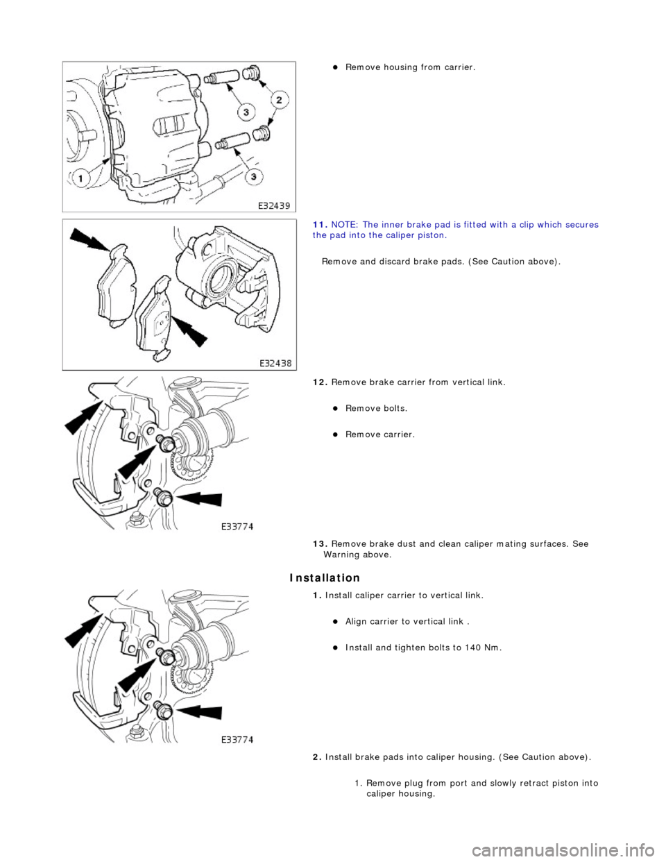
R
emove housing from carrier.
11
.
NOTE: The inner brake pad is fitt ed with a clip which secures
the pad into the caliper piston.
Remove and discard brake pa ds. (See Caution above).
12
.
Remove brake carrier from vertical link.
Re
move bolts.
R
emove carrier.
13. Remove brake dust and clean caliper mating surfaces. See
Warning above.
1. Install
caliper carrier to vertical link.
Al
ign carrier to vertical link .
Install and tigh
ten bolts to 140 Nm.
2. Install brake pads in to caliper housing. (See Caution above).
1. Remove plug from port and slowly retract piston into caliper housing.
Page 347 of 2490

Front Disc Brake - Brake CaliperVehicles With: High Performance Brakes
Re
moval and Installation
Remov
al
S
pecial Tool(s)
Brake Pedal
Hold Tool
JDS 9013
1. WARNING: BRAKE DUST, IF INHALED CAN DAMAGE
YOUR HEALTH. ALWAYS REMOVE BRAKE DUST USING A VACUUM
BRUSH. DO NOT USE A COMPRE SSED-AIR LINE TO DISPERSE
BRAKE DUST INTO THE ATMOSPHERE.
• CAUTIONS:
Replacement of nuts and bolts: Various thread-locking
devices are used on nuts and bolts throughout the vehicle. These
devices restrict the number of ti mes a nut or bolt can be used.
See section 100-00 for information.
Remove brake fluid spillage immediately from paint work,
with clean water.
The Brembo caliper is aligned to the brake disc when it is
first installed to the vehicle, therefore, care must be taken not to
disturb this alignment. When removing the caliper; remove the
bolts that secure the anchor bracket to the vertical link only. DO
NOT loosen any other caliper bolts.
Open engine compartment and fit paint work protection covers
to fenders.
2. R
aise vehicle on a four-post lift.
3. Raise front of vehicle and support on stands. Refer to Section
100-02.
4. Remove front wheels. Refe r to operation 74.20.05.
5. NOTE
: The following three pictorial procedures must be
carried-out to minimize brake fl uid loss when disconnecting the
brake hose.
Open Left-Hand-Front and Left-H and-Rear caliper bleed nipples.
Connect
a bleed tube and co
ntainer to the calipers.
O
pen bleed nipples.
6. Depress and hold down brak e pedal at the specified
measurement using the special tool.
Page 349 of 2490

I
nstallation
4
. Remove brake pads.
11
.
CAUTION: Only remove the bolts securing the caliper
anchor bracket to the vertical link. Refer to caution above for
more information.
Remove caliper from vertical link.
Re
move bolts.
12
.
Remove brake dust and clean mating surfaces. See Warning
above.
1. Install
caliper to vertical link.
Install and tigh
ten bolts to 180 Nm.
2. CAUTI
ONS:
Retracting the caliper piston may cause the fluid reservoir
to over-flow. Remove brake flui d spillage immediately from paint
work, with clean water.
Note the condition of pins and 'R' clips and replace if
necessary.
Install brake pads into caliper.
Sl
owly retract caliper pistons.
1. Install pads.
Page 352 of 2490
In
stallation
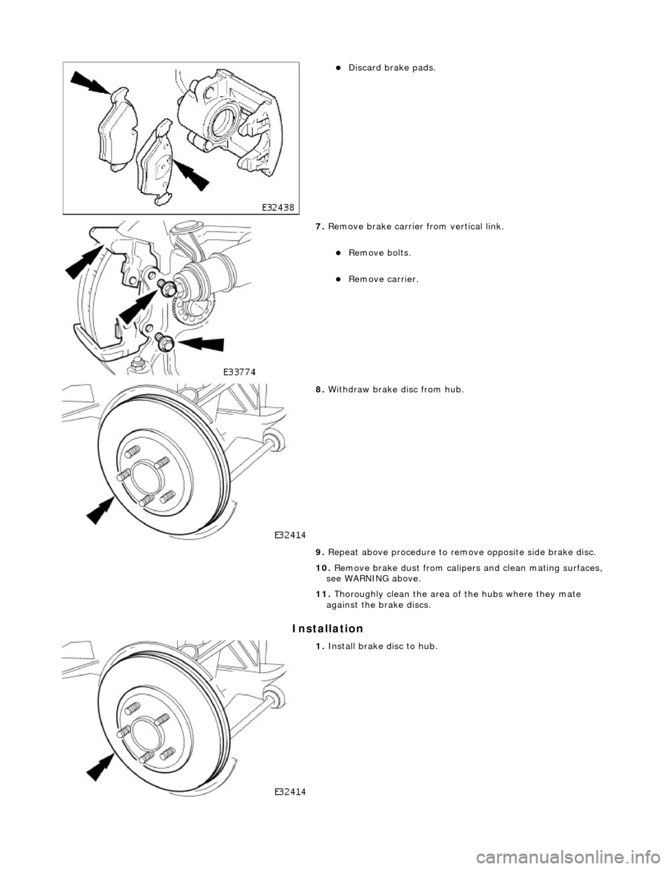
Discard b
rake pads.
7. Re
move brake carrier from vertical link.
Re
mo
ve bolts.
R
e
move carrier.
8. With draw brake disc from
hub.
9. Repeat above procedure to remo ve opposite side brake disc.
10. Remove brake dust from calipers and clean mating surfaces,
see WARNING above.
11. Thoroughly clean the area of the hubs where they mate
against the br ake discs.
1. Install brake disc to hu
b.
Page 356 of 2490
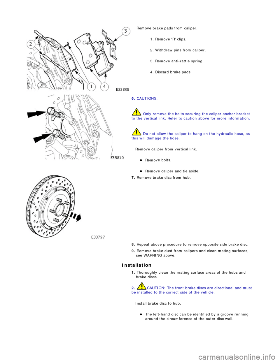
In
stallation
Remove brake pa
ds from caliper.
1. Remove 'R' clips.
2. Withdraw pins from caliper.
3. Remove anti-rattle spring.
4. Discard brake pads.
6. CAUTI O
NS:
Only remove the bolts securi ng the caliper anchor bracket
to the vertical link. Refer to ca ution above for more information.
Do not allow the caliper to hang on the hydraulic hose, as
this will damage the hose.
Remove caliper from vertical link.
Re mo
ve bolts.
Remove caliper and
tie aside.
7.
Remove brake disc from hu
b.
8. Repeat above procedure to remo ve opposite side brake disc.
9. Remove brake dust from calipers and clean mating surfaces,
see WARNING above.
1. Thoroughly clean the mating surface areas of the hubs and
brake discs.
2. CAUTION: The front brake disc s are directional and must
be installed to the correct side of the vehicle.
Install brake di sc to hub.
The left-hand disc can be iden tified by a groo
ve running
around the circumference of the outer disc wall.
Page 359 of 2490
Front Dis
c Brake - Brake PadsVe
hicles With: Standard Brakes
Re
moval and Installation
Remov
al
W
ARNING: BRAKE DUST, IF INHALED CAN DAMAGE YOUR
HEALTH. ALWAYS REMOVE BRAKE DUST USING A VACUUM
BRUSH. DO NOT USE A COMPRESSED-AIR LINE TO DISPERSE BRAKE DUST INTO THE ATMOSPHERE.
CAUTION: Replacement of nuts and bolts: Various thread-locking devices are used on nuts and bolts throughout the
vehicle. These devices restrict the number of times a nut or bolt can be used. See section 100-00 for information.
1. O
pen engine compartment and fit
paint work protection covers
to fenders.
2. Raise front of vehicle and suppo rt on stands. See Section 100-
02.
3. Remove front wheels. See Section 204-04.
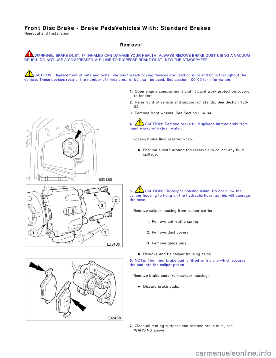
4. CAUTI
ON: Remove brake flui
d spillage immediately from
paint work, with clean water.
Loosen brake fluid reservoir-cap.
Position a cloth around the
reservoir to collect any fluid
spillage.
5. CAU
TION: Tie caliper housing aside. Do not allow the
caliper housing to hang on the hydraulic hose, as this will damage
the hose.
Remove caliper housing from caliper carrier.
1. Remove anti-rattle spring.
2. Remove dust covers.
3. Remove guide pins.
Re
move and tie caliper housing aside.
6.
NO
TE: The inner brake pad is fitt
ed with a clip which secures
the pad into the caliper piston.
Remove brake pads from caliper housing.
Discard
brake pads.
7. Clean all mating surfaces and remove brake dust, see
WARNING above.