panel JAGUAR X308 1998 2.G Workshop Manual
[x] Cancel search | Manufacturer: JAGUAR, Model Year: 1998, Model line: X308, Model: JAGUAR X308 1998 2.GPages: 2490, PDF Size: 69.81 MB
Page 2231 of 2490

In
strument Panel and Console - Floor Console Finish Panel Bracket
Rem
oval and Installation
Remov
al
Installation
1.
Remove 'J' gate finisher. Refer to 76.25.24.
2.
Slacken and remove the two front nuts and two rear screws
securing the retaining panel.
3.
Position retaining panel for access, disconnect SPORT mode and
cruise control ON/OFF switch multiplugs and remove retaining
panel complete with switches.
4. Remove switches from retaining panel.
5.
Remove and discard bushes from retaining panel.
1. Fit and fully seat new bushes in retaining panel.
2. Fit and fully seat SPORT mode and cruise control ON/OFF
switches in retaining panel.
3. Position retaining panel for access and connect SPORT mode and
cruise control ON/OFF switch multiplugs.
4. Fully seat retaining panel and fit and tighten securing nuts and
screws.
5. Fit 'J' gate surround finisher. Refer to 76.25.24.
Page 2232 of 2490

Instrument Panel and Console - Floor Console Stowage Compartment
Removal and Installation
Removal
Installation
1.
Open console gl ove box lid.
2. Slacken and remove the glove box lid stay securing screw and
remove lid stay.
3. Slacken and remove glove box latch securing screws and
remove latch assembly.
4. Slacken and remove glovebox liner rear securing screws.
5. Remove glovebox liner from vehicle.
1. Position glovebox liner in console.
2. Fit and tighten liner rear securing screws.
3. Position latch assembly on line r and fit and tighten securing
screws.
4. Fit and tighten check arm to lid securing screw.
5. Position lid to stay and fit and tighten securing screw.
6. Close glovebox lid.
Page 2233 of 2490

Instrument Panel and Console - Floor Console Stowage Compartment Lid
Removal and Installation
Removal
1. Open glovebox lid.
2. Slacken and remove lid stay se curing screw and remove stay from lid.
3. Slacken and remove glovebox latch securing screws and
remove latch from glovebox.
4. Slacken and remove glovebox li ner rear securing screws and
remove liner for access.
5. Slacken and remove remaining gl ovebox hinge securing screw.
Page 2235 of 2490

Instrument Panel and Console - Glove Compartment
Removal and Installation
Removal
Installation
1.
Open glovebox.
2. Supporting the glovebox, slac ken and remove the four top
securing screws.
3. Slacken and remove the two glovebox lower outer securing
screws.
4. Withdraw glovebox for access and disconnect the two
illumination harness connectors.
5. Remove glovebox from vehicle.
1. Position glovebox for access and connect illumination harness.
2. Position and fully seat glovebox.
3. Fit but do not tighten the lower securing screws.
4. Fit and fully tighten the upper securing screws.
5. Close glovebox lid.
6. Fully tighten the lower securing screws.
Page 2236 of 2490

Instrument Panel and Console - Glove Compartment Lid
Removal and Installation
Removal
Installation
1.
Remove glovebox. Refer to 76.52.03.
2. Open glovebox lid and lift barbed hook to release damper
cord loop from lid..
3. Slacken and remove the two lid hinge securing nuts.
4. Remove glovebox lid.
1. Fit glovebox lid to liner.
2. Position lid on hinges and fi t but do not tighten securing
screws.
3. Fit damper cord loop to lid.
4. Position and fit glovebox. Refer to 76.52.03.
5. Adjust lid position to achieve satisfactory all-round clearance
and catch operation.
6. Fully tighten hinge securing screws.
Page 2237 of 2490

Instrument Panel and Console - Glove Compartment Lid Damper
Removal and Installation
Removal
Installation
1.
remove glovebox assembly. Refer to 76.52.03.
2. Disconnect glovebox damper cord end loop from damper and
route cord through the liner guide.
3. Slacken and remove the two damp er securing nuts and remove damper from liner.
1. Position damper on liner
2. Fit and tighten damper securing nuts.
3. Route damper cord through liner guide and connect end loop to
damper.
Page 2238 of 2490

Instrument Panel and Console - Glove Compartment Liner
Removal and Installation
Removal
Installation
1.
Remove glovebox refer to 76.52.03.
2. Remove glovebox lid. Tefer to 76.52.02.
3. Remove glovebox damper. Refer to 76.52.22.
4. Release damper cord guide retaining tangs and remove guide
from bracket.
5. Position liner for access and ca refully remove switch assembly
from housing.
1. Route illumination switch harness into switch housing.
2. Connect switch to harness mult iplugs and fit and fully seat
switch in housing.
3. Secure harness in liner clips.
4. Fit lid damper to liner. Refer to 76.52.22.
5. Fit damper cord guide to bracket.
6. Route damper cord through guide and connect to damper.
7. Fit glovebox lid. refer to 76.52.02.
8. Fit glovebox. Refer to 76.52.03.
Page 2239 of 2490

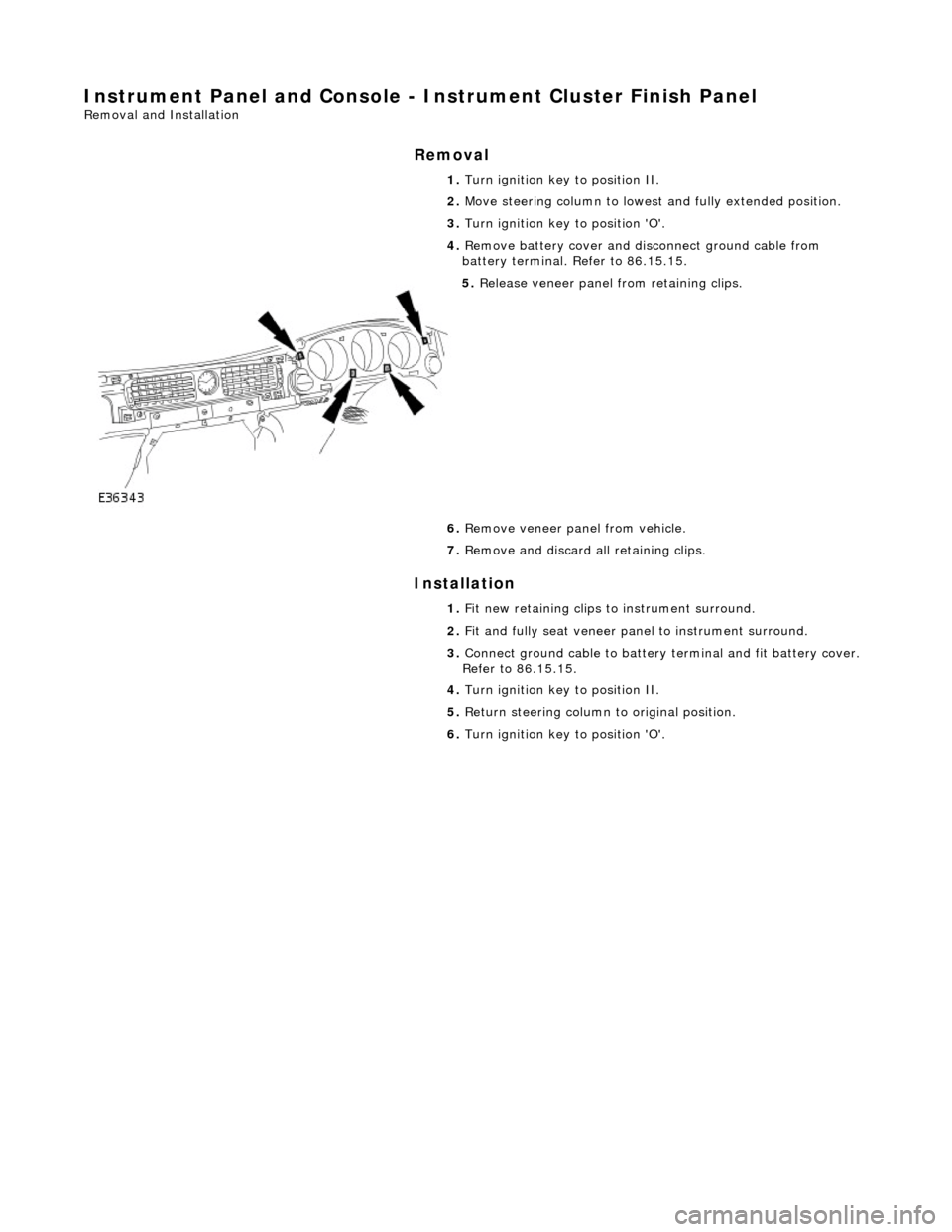
Instrument Panel and Console - Instrument Cluster Finish Panel
Removal and Installation
Removal
Installation
1.
Turn ignition key to position II.
2. Move steering column to lowest and fully extended position.
3. Turn ignition key to position 'O'.
4. Remove battery cover and disc onnect ground cable from
battery terminal. Refer to 86.15.15.
5. Release veneer panel from retaining clips.
6. Remove veneer panel from vehicle.
7. Remove and discard all retaining clips.
1. Fit new retaining clips to instrument surround.
2. Fit and fully seat veneer pa nel to instrument surround.
3. Connect ground cable to battery terminal and fit battery cover.
Refer to 86.15.15.
4. Turn ignition key to position II.
5. Return steering column to original position.
6. Turn ignition key to position 'O'.
Page 2240 of 2490

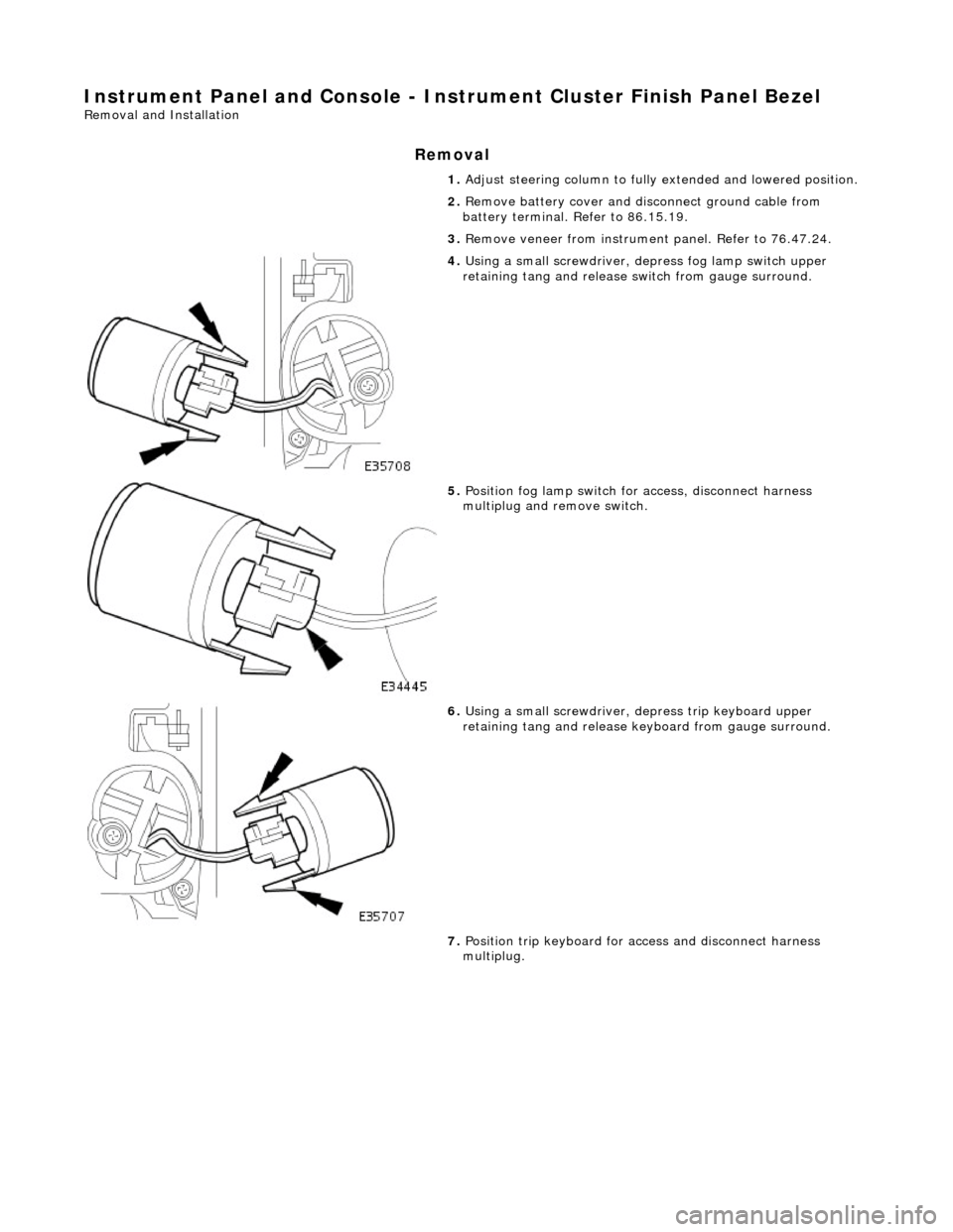
Instrument Panel and Console - Instrument Cluster Finish Panel Bezel
Removal and Installation
Removal
1. Adjust steering column to full y extended and lowered position.
2. Remove battery cover and disc onnect ground cable from
battery terminal. Refer to 86.15.19.
3. Remove veneer from instrument panel. Refer to 76.47.24.
4. Using a small screwdriver, de press fog lamp switch upper
retaining tang and release sw itch from gauge surround.
5. Position fog lamp switch fo r access, disconnect harness
multiplug and remove switch.
6. Using a small screwdriver, depress trip keyboard upper
retaining tang and release ke yboard from gauge surround.
7. Position trip keyboard for ac cess and disconnect harness
multiplug.
Page 2241 of 2490

Installation
8. Slacken and remove four screws securing major gauge
module/surround to fascia and withdraw surround.
1. Position major gauge surround on panel, routing harness
multiplugs through apertures.
2. Fit and tighten screws securing major gauge module/surround
to fascia.
3. Connect harness multiplug to tr ip keyboard and fit and fully
seat keyboard in gauge surround, ensuring correct location of
retaining tangs
4. Connect harness multiplug to fog lamp switch and fit and fully
seat switch in gaug e surround, ensuring correct location of
tangs.
5. Fit veneer panel. Refer to 76.47.24.
6. Connect ground cable to battery terminal and fit battery cover.
Refer to 86.15.15.
7. Return steering column to original position.