panel JAGUAR X308 1998 2.G Workshop Manual
[x] Cancel search | Manufacturer: JAGUAR, Model Year: 1998, Model line: X308, Model: JAGUAR X308 1998 2.GPages: 2490, PDF Size: 69.81 MB
Page 2090 of 2490

Interior Trim and Ornamentation - Rear Door Trim Panel Finish Panel
Removal and Installation
Removal
Installation
1. Remove interior door handle escutcheon.
Remove cover from door ha ndle escutcheon securing
screw and slacken and remove screw.
Pull door handle inwards and exercising care to avoid
damaging tweeter, remove escutcheon from casing.
2. Remove veneer panel from casing.
1. Using a thin plastic leve r, carefully ease rear of
veneer panel inwards to release the two rear
securing tangs.
2. Slide veneer panel re arwards to release front
retainers.
1. Position veneer panel on casing and slide forward to engage
front retainers.
2. Using a soft pad or cloth, press re ar of panel firmly to seat the
securing tangs.
3. Position door handle escutche on on casing, fit and tighten
securing screw and fit cover over screw.
Page 2091 of 2490

Interior Trim and Ornamentation - Rear Door Trim Panel
Removal and Installation
Removal
1. Remove interior door handle escutcheon.
1. Remove cover from door handle escutcheon securing screw and slac ken and remove screw.
2. Pull door handle inwards and exercising care to avoid damaging tweeter, remove escutcheon from
casing.
2. Remove door casing veneer panel. Refer to 76.47.12.
3. Slacken and remove the armres t centre securing screw.
4. Carefully release the six fastener s (seven on long wheelbase)
securing lower section of casing to door.
5. Lift rear edge of door casing to release retaining clip housing
from door panel.
Page 2094 of 2490

primary water shedder is undamag
ed and correctly attached to
door inner panel.
Align and fit inner waist seal.
8. Check that armrest tang locater and screw insert are correctly
positioned in door panel.
9. Position casing for access and connect speaker, puddle lamp
and switchpack harnesses.
10. Finally position casing locating fold over waist flange and
firmly press armrest to locate retaining tang in door panel.
11. Commencing at front , press and firmly seat casing lower
fasteners in door inserts
12. Fit and tighten armrest centre se curing screw in door insert.
13. Fit door veneer panel. Refer to 76.47.12.
14. Position door handle escutche on on casing, fit and tighten
securing screw and fit cover over screw.
Page 2096 of 2490

Interior Trim and Ornamentation - Rear Door Window Control Switch
Finish Panel
Removal and Installation
Removal
Installation
1.
Remove door casing veneer panel. Refer to 76.47.12.
2. Remove door casing. Refer to 76.34.04.
3. Remove door armrest and remo ve switch/ashtray assembly
from armrest. Refer to 76.34.23.
4. Slacken and remove screws securing veneer panels to door
glass switch/ashtray assembly.
5. Remove veneer panels from switch/ashtray assembly.
1. Position veneer panel over switch/ashtray assembly and fit and
tighten securing screws.
2. Position switch/ashtray assembly on armrest and fit and
tighten the two securing screws.
3. Fit armrest to door casing. Refer to 76.34.23.
4. Fit casing to door. Refer to 76.34.04.
Page 2097 of 2490

Interior Trim and Ornamentation - Scuff Plate Trim Panel
Removal and Installation
Removal
Installation
1. NOTE: The finisher can be easily damaged, care must therefore be exercised during removal.
Using a thin plastic lever and starting at one end, carefully
remove the treadplate finisher and place face uppermost on
sheet of clean dry polythene.
2. Remove treadplate securing sc rews and remove treadplate.
1. Ensure that draught welt is correctly positioned and fully
seated on aperture flange.
2. Position sill tread plate and install three securing screws.
3. Ensure that sill contact area is clean and dry.
4. Install treadplate finisher, pressing firmly into place. If finisher
has been renewe d, remove protective film.
Page 2103 of 2490

Exterior Trim and Ornamentation - Door Moulding
Removal and Installation
Removal
Installation
1.
Apply suitable protecti ve tape to immediately adjacent areas of
paintwork.
2. Using a hand-held heat gun, appply heat uniformly along
moulding length.
3. Applying local heat at one end and using a suitable thin lever
to avoid damaging paintwork, progressively ease moulding
away from door panel.
4. Discard moulding and remove protective tape.
5. Remove any residual adhesive and thoroughly clean area using
white spirit.
1. NOTE: Optimum adhesion is achi eved by warming body panel
and moulding to 65deg C.
Using white spirit ensure that mounting area is clean, dry and
de-greased.
2. Remove protective backing tape from moulding.
3. NOTE: Do not allow moulding to contact the body panel until it
is correctly aligned.
Heat moulding and moun ting area to 65degC.)
4. Aligning with adjacent mouldings or to match opposite side of
vehicle, press new moulding firmly onto body panel.
5. Apply hand pressure along moulding length to ensure
satisfactory adhesion.
6. Allow moulding and door panel to cool , then thoroughly clean
both using white spirit.
7. Apply a coat of suitab le polish to moulding and body panel.
Page 2104 of 2490

Exterior Trim and Ornamentation - Front Fender Moulding
Removal and Installation
Removal
Installation
1.
Apply suitable protecti ve tape to immediately adjacent areas of
paintwork.
2. Using a hand-held heat gun, appply heat uniformly along
moulding length.
3. Applying local heat at one end and using a suitable thin lever
to avoid damaging paintwork, progressively ease moulding
away from fender.
4. Discard moulding and remove protective tape.
5. Remove any residual adhesive and thoroughly clean area using
white spirit.
1. NOTE: Optimum adhesion is achi eved by warming body panel
and moulding to 65deg C.
Using white spirit ensure that mounting area is clean, dry and
de-greased.
2. Remove protective backing tape from moulding.
3. NOTE: Do not allow moulding to contact the fender until it is
correctly aligned.
Heat moulding and mounting area to 65deg C.
4. Aligning with adjacent mouldings or to match opposite side of
vehicle, press new mouldi ng firmly onto fender.
5. Apply hand pressure along moulding length to ensure
satisfactory adhesion.
6. Allow moulding and fender to cool , then thoroughly clean both
using white spirit.
7. Apply a coat of suitable poli sh to moulding and fender.
Page 2121 of 2490

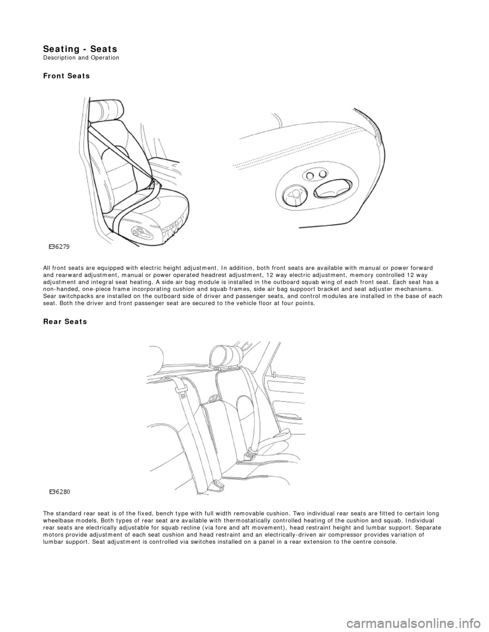
Seating - Seats Description and Operation
Front Seats
All front seats are equipped with electric height adjustment. In addition, both front seats are available with manual or power forward
and rearward adjustment, manual or powe r operated headrest adjustment, 12 way elec tric adjustment, memory controlled 12 way
adjustment and integral seat heating. A side air bag module is installed in the outboard squab wing of each front seat. Each se at has a
non-handed, one-piece frame incorporating cushion and squab frames , side air bag suppoort bracket and seat adjuster mechanisms.
Sear switchpacks are installed on the outboa rd side of driver and passenger seats, and control modules are installed in the bas e of each
seat. Both the driver and front passenger seat ar e secured to the vehicle floor at four points.
Rear Seats
The standard rear seat is of the fixed, bench type with full wi dth removable cushion. Two individual rear seats are fitted to certain long
wheelbase models. Both types of rear seat are available with thermostatically controlled heating of the cushion and squab. Indi vidual
rear seats are electrically adjustable for squab recline (via fore and aft moveme nt), head restraint height and lumbar support. Separate
motors provide adjustment of each seat cushion and head restraint and an electrica lly-driven air compressor provides variation of
lumbar support. Seat adjustment is controll ed via switches installed on a panel in a rear extension to the centre console.
Page 2131 of 2490

Seating - Front Seat Backrest Trim Panel
Removal and Installation
Removal
Installation
1. Slacken and remove the two ba ck finisher lower securing
screws.
2. Release back finisher from the side securing clips.
3. Release back finisher upper fir tree fasteners and remove back
finisher from seat.
1. Fit and align back finisher to seat.
2. Fully seat back finisher upper securing studs.
3. Position and fully seat fini sher side securing clips.
4. Fit and tighten the two back finisher lower securing screws.
Page 2157 of 2490

Installation
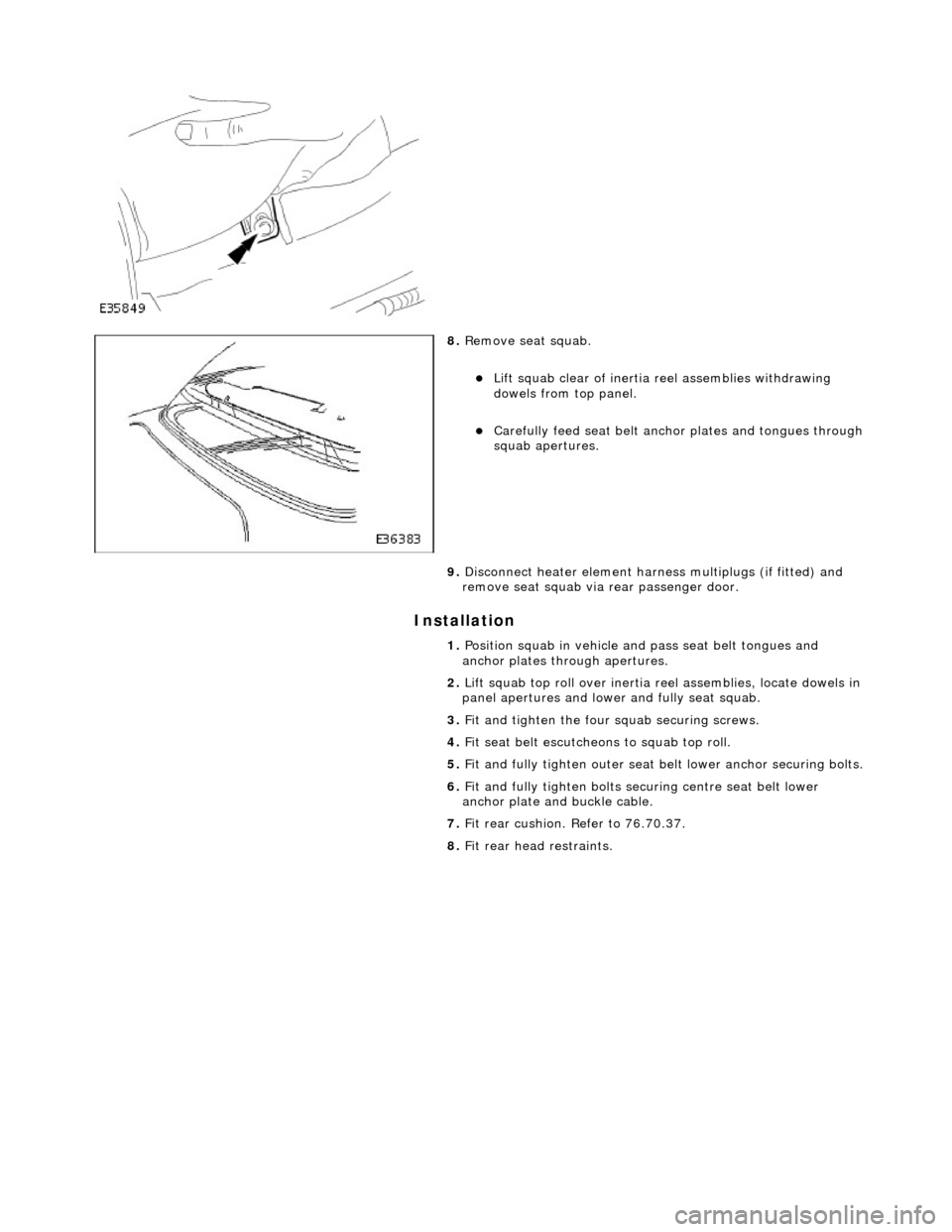
8. Remove seat squab.
Lift squab clear of inertia reel assemblies withdrawing
dowels from top panel.
Carefully feed seat belt anch or plates and tongues through squab apertures.
9. Disconnect heater element harness multiplugs (if fitted) and
remove seat squab via rear passenger door.
1. Position squab in vehicle and pass seat belt tongues and
anchor plates through apertures.
2. Lift squab top roll over inertia reel assemblies, locate dowels in
panel apertures and lower and fully seat squab.
3. Fit and tighten the four squab securing screws.
4. Fit seat belt escutcheons to squab top roll.
5. Fit and fully tighten outer seat be lt lower anchor securing bolts.
6. Fit and fully tighten bolts securing centre seat belt lower
anchor plate and buckle cable.
7. Fit rear cushion. Refer to 76.70.37.
8. Fit rear head restraints.