vi number JAGUAR X308 1998 2.G Workshop Manual
[x] Cancel search | Manufacturer: JAGUAR, Model Year: 1998, Model line: X308, Model: JAGUAR X308 1998 2.GPages: 2490, PDF Size: 69.81 MB
Page 1910 of 2490

Speakers - Speakers
Description and Operation
Speaker Location
Parts List
ItemPart NumberDescription
1—Door Speaker
2—Front Door Tweeter (Base System)
3—Rear Door Tweeter
4—CD Autochanger (P remium System)
5—Amplifier (Premium System)
6—Sub-woofer (Premium System)
7—'A' Post Tweeter (Premium System)
Page 1919 of 2490
Exterior Lighting - Exterior Lighting
Description and Operation
A multi-function switch located on the left stalk of the steering column switch assembly permits selection of either parking
(side), headlamps, auto-headlamp or off. Selection of a particular mode provides the appropriate input to the body
processor module (BPM).
Where the auto headlamp function is incorporated, a light sensor in the interior rear view mirror monitors ambient light and
provides an input to the BPM. The BPM responds by switching the low beam headlamps on or off as appropriate for the
prevailing light conditions.
The front and rear fog lamp switch is located on the fascia outboard of the steering column.
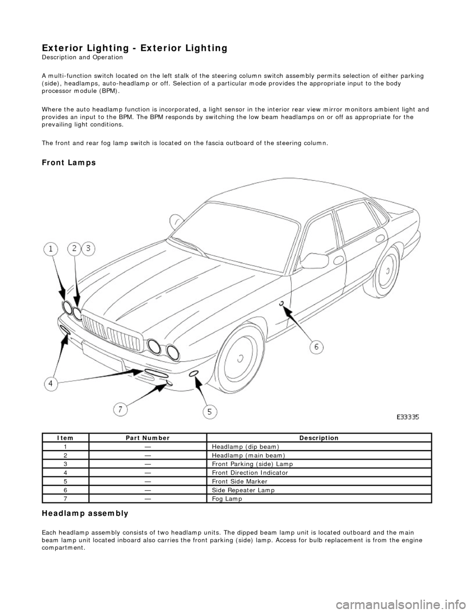
Front Lamps
Headlamp assembly
Each headlamp assembly consists of tw o headlamp units. The dipped beam lamp unit is located outboard and the main
beam lamp unit located inboard also carries the front parking (side) lamp. Access for bulb replacement is from the engine
compartment.
ItemPart NumberDescription
1—Headlamp (dip beam)
2—Headlamp (main beam)
3—Front Parking (side) Lamp
4—Front Direction Indicator
5—Front Side Marker
6—Side Repeater Lamp
7—Fog Lamp
Page 1920 of 2490
Direction indicator and side marker lamps
Each front direction indicator and side marker lamp is retained in the bumper cover by a lug at one end and a spring clip at
the other end. The side marker lamps are not electrically connected for certain markets.
The side repeater lamps are secured by sp ring clips on the lower edge of the lamp unit. In certain markets Jaguar leaper
badges are substituted for side repeater lamps.
Fog lamps
The fog lamps are located in recesses in the front bump er and secured by three screws. The la mps which are not
interchangeable left to right, are accessed from the rear of the bumper.
Operation
All lamps are controlled by the BPM which provides an appropriate output in response to an input received when a selected
switch is operated.
All lamps receive an input direct from th e BPM with the exception of the main be am, dip beam and front fog lamps which
receive an input from the BPM vi a the respective relays and fuses; refer to section 418-01.
Fault analysis must be undertaken using the PDU. Refer to Diagnosis and Testing.
Consult the relevant Electrical Guid e for details of circuit operation.
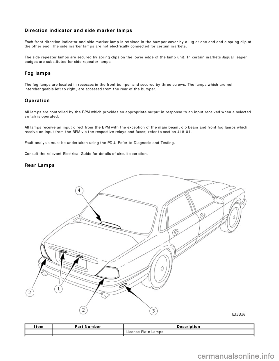
Rear Lamps
ItemPart NumberDescription
1—License Plate Lamps
Page 1945 of 2490

Exterior
Lighting - License Plate Lamp
Rem
oval and Installation
Remov
al
Installation
1.
Remove battery cover and disconnect ground cable from battery
terminal. Refer to 86.15.19.
2. Remove trunk lamp assemblies. Refer to 86.45.16
3. Remove trunk lid upper trim finisher. Refer to 76.43.79.
4.
From inside trunk lid, press tang at each side of lamp and push
lamp outwards.
5.
Withdraw number plate lamp from trunk lid for access and
disconnect lamp harness multiplug.
6.
Remove and discard foam seal from lamp.
1. Install new foam seal to number plate lamp.
2. Position number plate lamp at trunk lid and connect harness
multiplug.
3. Install number plate lamp in trunk lid aperture ensuring that seal
seats correctly.
4. Install trunk upper trim finisher. Refer to 76.43.79.
5. Install trunk lamp assemb lies. Refer to 86.45.16.
6. Connect ground cable to battery terminal and fit battery cover.
Refer to 86.15.15.
Page 1946 of 2490

Exterior Lighting - License Plate Lamp Bulb
Removal and Installation
Removal
Installation
1. Remove the two number plate lamp lens securing screws.
2. Remove lens from lamp assembly and discard gasket.
3. Remove bulb from lamp assembly.
1. Install bulb in lamp assembly.
2. Install new lens gasket to lamp assembly.
3. Ensuring that gasket is correctly positioned, install lens on
lamp assembly.
4. Install lens securing screws.
Page 1962 of 2490
Interior Lighting - Interior Lighting
Description and Operation
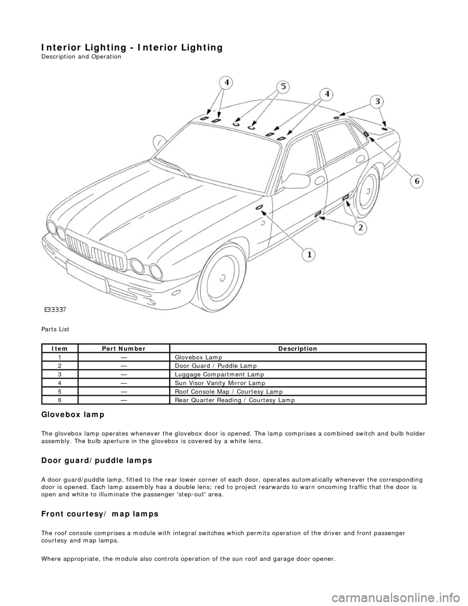
Parts List
Glovebox lamp
The glovebox lamp operates whenever the glovebox door is opened. The lamp comprises a combined switch and bulb holder assembly. The bulb aperture in the glovebox is covered by a white lens.
Door guard/puddle lamps
A door guard/puddle lamp, fitted to the rear lower corner of each door, operates automatically whenever the corresponding
door is opened. Each lamp assembly has a double lens; red to project rearwards to warn oncoming traffic that the door is
open and white to illuminate the passenger 'step-out' area.
Front courtesy/ map lamps
The roof console comprises a module with integral switches which permits operation of the dr iver and front passenger
courtesy and map lamps.
Where appropriate, the module also controls operation of the su n roof and garage door opener.
ItemPart NumberDescription
1—Glovebox Lamp
2—Door Guard / Puddle Lamp
3—Luggage Compartment Lamp
4—Sun Visor Vanity Mirror Lamp
5—Roof Console Map / Courtesy Lamp
6—Rear Quarter Reading / Courtesy Lamp
Page 1964 of 2490

Interior Lighting - Interior Lighting
Diagnosis and Testing
Tests Using the Portable Diagnostic Unit
Refer to PDU User Guide
The complexity of the electronics involved with the various Electronic Control Modules and the multiplexed communication
networks, preclude the use of workshop general electrical test equipment. Therefore, reference should be made to the PDU
User Guide for detailed inst ructions on testing the interior lamps and circuits.
The PDU systematically tests and analyses the lamp assemblies, the bulbs and the electrical connections to them. It should
be noted that the lamps are not wired directly to the switches.
The lamps are controlled directly by the Bo dy Processor (it has a sufficient number of high power output stages to drive the
lamps / relays compared to other module s) except for the door guard / puddle lamps and the rear passenger reading lamps.
The Body Processor Module receives messages on the SCP network from the door modules relating to door ajar / closed /
locked status, sensed by the door courtesy switch(es).
Where a fault involving a lamp is indicated by the PDU, be fore replacing suspect components, some basic diagnostic
methods may be necessary to confirm that connecti ons are good and that wiring is not damaged.
Page 1972 of 2490
Daytime Running Lamps (DRL) - Daytime Running Lamps (DRL)
Diagnosis and Testing
Tests Using the Portable Diagnostic Unit
Refer to PDU User Guide
The complexity of the electronics involved with the Body Pr ocessor and the multiplexed communication networks which are
associated with it, preclude the use of wo rkshop general electrical test equipment. Therefore, reference should be made to
the PDU User Guide for detail ed instructions on testing the Daytime Running Function.
The Daytime Running function is exactly the same as for the normal operation of the side lamps (or dipped beam, where
specified) in as much as the body processor drives the same lamps from the same outputs.
The body processor has been programmed to respond to an alternative set of cond itions in order to operate the lamps,
instead of waiting for a signal from the normal light switch.
The conditions which have to be set are; ignition switch se t to position II or III and sidelight switch set to OFF. The
sidelights, side marker lamps (if fitted and enabled), tail lights and number plate lights will all be switched ON.
The PDU systematically tests and analyses all functions of the daytime running lamps.
Where a fault is indicated, before replac ing a component, some basic diagnostic methods may be necessary to confirm that
connections are good and that wiring is not damaged.
Page 1973 of 2490
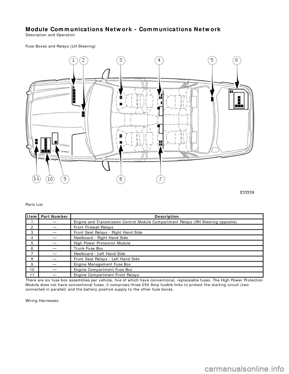
Module Communications Network - Communications Network
Description and Operation
Fuse Boxes and Relays (LH Steering)
Parts List
There are six fuse box assemblies per vehicle, five of which have conventional, replaceable fuses. The High Power Protection
Module does not have conventional fuses, it comprises three 250 Amp fusible links to protect the starting circuit (two
connected in parallel) and the battery positive supply to the other fuse boxes.
Wiring Harnesses
ItemPart NumberDescription
1—Engine and Transmission Cont rol Module Compartment Relays (RH Steering opposite)
2—Front Firewall Relays
3—Front Seat Relays - Right Hand Side
4—Heelboard - Right Hand Side
5—High Power Protection Module
6—Trunk Fuse Box
7—Heelboard - Left Hand Side
8—Front Seat Relays - Left Hand Side
9—Engine Management Fuse Box
10—Engine Compartment Fuse Box
11—Engine Compartment Front Relays
Page 1974 of 2490

Parts List
ItemPart NumberDescription
1—Bumper