body JAGUAR X308 1998 2.G Workshop Manual
[x] Cancel search | Manufacturer: JAGUAR, Model Year: 1998, Model line: X308, Model: JAGUAR X308 1998 2.GPages: 2490, PDF Size: 69.81 MB
Page 1371 of 2490

Automatic Transmission/Transaxle - 4.0L NA V8 - AJ27/3.2L NA V8 - AJ26
- Transmission Support Insulator
In-vehicle Repair
Removal
Installation
1. Raise the vehicle on a ramp to a suitable height for working on
the rear mounting.
2. Remove the bolt which secure s the engine rear mounting
rubber to the transmission.
3. Position a transmission jack under the transmission casing.
Take the weight of the transmission on the jack.
4. Remove the rear mounting rubber.
1. Slacken the four bolt s which secure the rear
crossmember to the vehicle floor.
2. Remove the two bolts which secure the mounting rubber to the crossmember.
3. Remove the mounting rubber.
1. Fit the mounting rubber assembly to position and tighten the
centre bolt to 30-40 Nm .
2. Tighten the crossmember to body bolts and the mounting
rubber to crossmember bolts to 22-28 Nm.
Page 1377 of 2490

16. Remove the engine rear mounting bracket.
1. Remove the engine rear mounting to bracket bolt.
2. Remove the mounting bracket to body bolts.
17. Detach the driveshaft from th e transmission drive flange.
If the transmission is to be refitted, mark the position of
the coupling to drive flange.
17. CAUTION: Under no circ umstances remove the
driveshaft to flexible coupling fixings.
Remove the transmission drive flange to flexible coupling
three fixings.
18. Lower the transmission unit by carefully releasing the engine
support beam and by loweri ng the transmission jack.
19. Detach the gear selector cable from the transmission unit.
1. Remove the selector cable ball pin to selector lever nut.
2. Remove the selector cable to transmission casing bolts.
20. Disconnect the transmission harness multiplug.
1. Rotate the locking lever to release.
2. Disconnect the multiplug.
Page 1388 of 2490

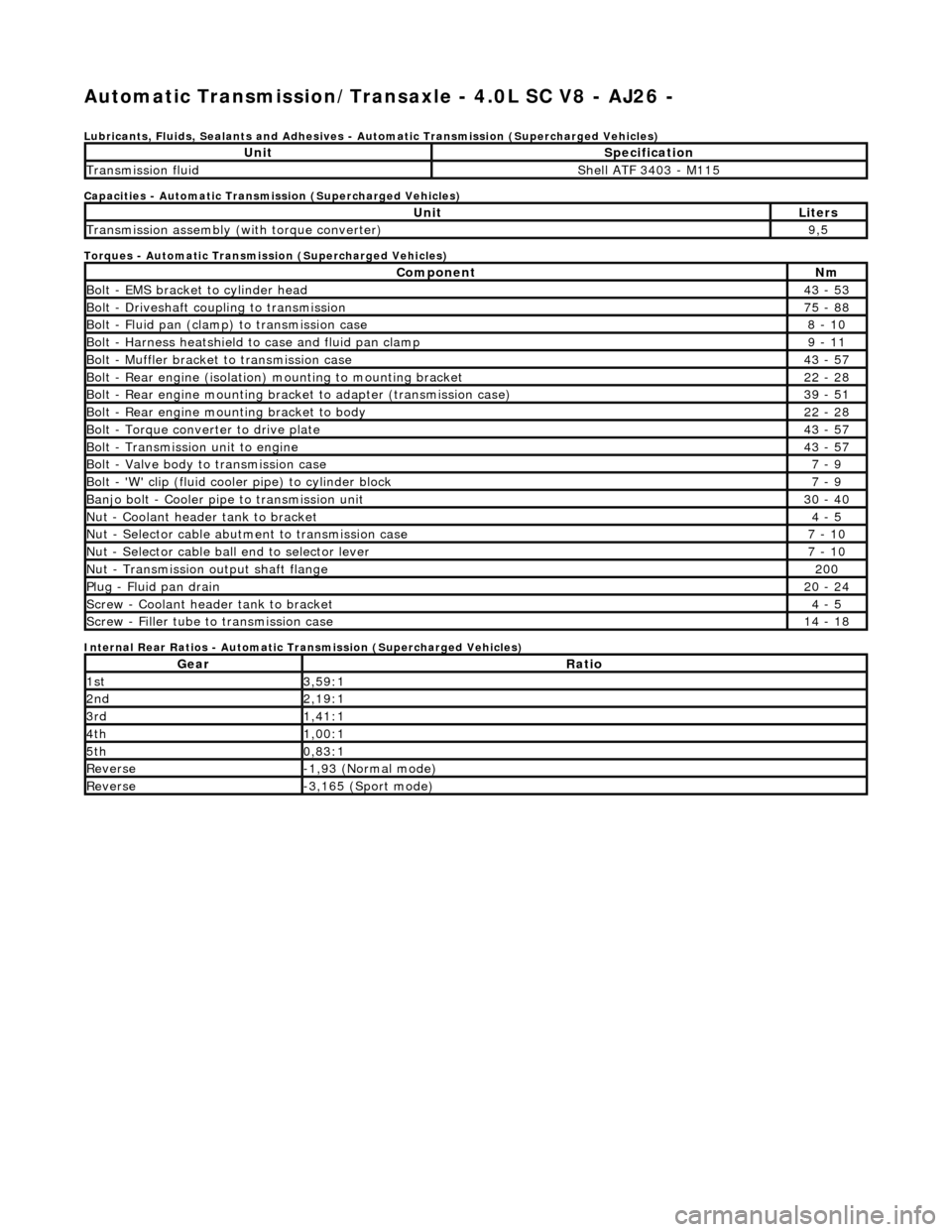
Automatic Transmission/Transaxle - 4.0L SC V8 - AJ26 -
Lubricants, Fluids, Sealants and Adhesives - Automatic Transmission (Supercharged Vehicles)
Capacities - Automatic Transmission (Supercharged Vehicles)
Torques - Automatic Transmission (Supercharged Vehicles)
Internal Rear Ratios - Automatic Transmission (Supercharged Vehicles)
UnitSpecification
Transmission fluidShell ATF 3403 - M115
UnitLiters
Transmission assembly (with torque converter)9,5
ComponentNm
Bolt - EMS bracket to cylinder head43 - 53
Bolt - Driveshaft coupling to transmission75 - 88
Bolt - Fluid pan (clamp) to transmission case8 - 10
Bolt - Harness heatshield to case and fluid pan clamp9 - 11
Bolt - Muffler bracket to transmission case43 - 57
Bolt - Rear engine (isolation) mounting to mounting bracket22 - 28
Bolt - Rear engine mounting brac ket to adapter (transmission case)39 - 51
Bolt - Rear engine mounting bracket to body22 - 28
Bolt - Torque converter to drive plate43 - 57
Bolt - Transmission unit to engine43 - 57
Bolt - Valve body to transmission case7 - 9
Bolt - 'W' clip (fluid cooler pipe) to cylinder block7 - 9
Banjo bolt - Cooler pipe to transmission unit30 - 40
Nut - Coolant header tank to bracket4 - 5
Nut - Selector cable abutment to transmission case7 - 10
Nut - Selector cable ball end to selector lever7 - 10
Nut - Transmission output shaft flange200
Plug - Fluid pan drain20 - 24
Screw - Coolant header tank to bracket4 - 5
Screw - Filler tube to transmission case14 - 18
GearRatio
1st3,59:1
2nd2,19:1
3rd1,41:1
4th1,00:1
5th0,83:1
Reverse-1,93 (Normal mode)
Reverse-3,165 (Sport mode)
Page 1401 of 2490

Pinpoint test A: P0740
DTC P0730 Incorrect gear ratioEngaged gear implausible / transmission
slipping Oil level low
Valve body assembly faulty
Transmission faulty
*
*
*
*GO to Pinpoint Test H *
DTC P0780 Shift malfunctionValve body assembly faulty
Transmission faulty
*
*GO to Pinpoint Test H *
PINPOINT TEST A : P0740
TEST CONDITIONSDETAILS/RESULTS/ACTIONS
A1: RETRIEVE DTCS
• NOTE: Battery and or ECM disconnection prior to scanning wi
ll erase all data, ensure that the correct DTC is present.
Connect the scan tool 1
Have the DTC(s) and freeze frame data been recorded?
Yes GO to A2
A2: CHECK TORQUE CONVERTER CLUTCH SOLENOID RESISTANCE
With, EM062 disconnected, measure the resistance between 1
Page 1412 of 2490

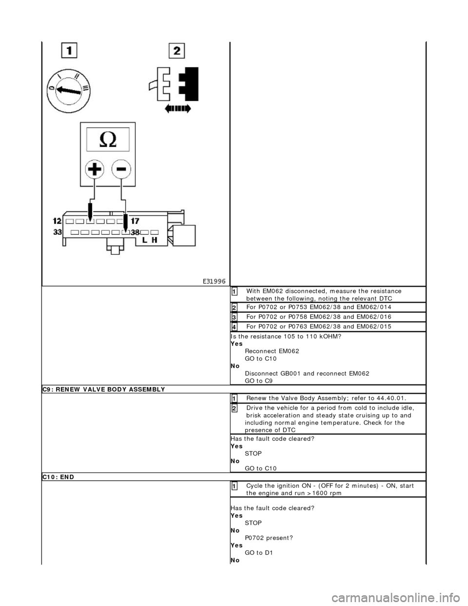
With EM062 disconnected, measure the resistance
between the following, noting the relevant DTC 1
For P0702 or P0753 EM062/38 and EM062/014 2
For P0702 or P0758 EM062/38 and EM062/016 3
For P0702 or P0763 EM062/38 and EM062/015 4
Is the resistance 105 to 110 kOHM?
Yes Reconnect EM062
GO to C10
No Disconnect GB001 and reconnect EM062
GO to C9
C9: RENEW VALVE BODY ASSEMBLY
Renew the Valve Body Assembly; refer to 44.40.01. 1
Drive the vehicle for a period from cold to include idle,
brisk acceleration and steady state cruising up to and
including normal engine temperature. Check for the
presence of DTC 2
Has the fault code cleared?
Yes STOP
No GO to C10
C10: END
Cycle the ignition ON - (OFF for 2 minutes) - ON, start
the engine and run >1600 rpm 1
Has the fault code cleared?
Yes STOP
No P0702 present?
Yes GO to D1
No
Page 1419 of 2490

Pinpoint test E: P0702
With EM062 disconnected, measure the resistance
between the following, noting the relevant DTC 1
For P0702 or P0748 EM062/38 and EM062/036 2
For P0702 or P1748 EM062/38 and EM062/037 3
Is the resistance 16 to 18 kOHM?
Yes Reconnect EM062
GO to D9
No Renew the Valve Body Assembly; refer to 44.40.01.
Drive the vehicle for a period from cold to include idle,
brisk acceleration and steady state cruising up to and
including normal engine temperature.
GO to D9
D9: END
Cycle the ignition ON - (OFF for 2 minutes) - ON, start
the engine and run >1600 rpm 1
Has the fault code cleared?
Yes STOP
No Contact Jaguar Service
PINPOINT TEST E : P0702
TEST CONDITIONSDETAILS/RESULTS/ACTIONS
E1: RETRIEVE DTCS
• NOTE: Battery and or ECM disconnection prior to scanning wi ll erase all data, ensure that the correct DTC is present.
Page 1427 of 2490

Pinpoint test H: P0730, P0780
Connect the scan tool 1
Have the DTC(s) and freeze frame data been recorded?
Yes GO to G2
G2: RENEW TCM
Renew the TCM 1
Has the TCM been renewed?
Yes GO to G3
G3: END
• NOTE: The following step must be carried out in order that sy stem adaptions can take place.
Drive the vehicle for a period from cold to include idle, brisk
acceleration and steady state cruising up to and including
normal engine temperature. Check for the presence of DTC 1
Has the fault code cleared?
Yes STOP
No Contact Jaguar Service
PINPOINT TEST H : P0730, P0780
TEST CONDITIONSDETAILS/RESULTS/ACTIONS
H1: RETRIEVE DTCS
• NOTE: Battery and or ECM disconnection prior to scanning wi ll erase all data, ensure that the correct DTC is present.
Connect the scan tool 1
Have the DTC(s) and freeze frame data been recorded?
Yes GO to H2
H2: RENEW VALVE BODY ASSEMBLY
Renew the valve body assembly 1
Drive the vehicle for a period from cold to include idle, brisk
acceleration and steady state cruising up to and including
normal engine temperature. Check for the presence of DTC 2
Has the fault code cleared?
Page 1433 of 2490

Automatic Transmission/Transaxle - 4.0L SC V8 - AJ26 - Extension
Housing Seal
In-vehicle Repair
Removal
Special Tool(s)
Oil seal replacer
307-378
Driveshaft wrench
205-053
1. Disconnect the battery ground lead.
2. Select N and choc the road wheels.
3. Remove the front muffler, re fer to Operation 30.10.18.
4. Remove the engine rear mounting bracket.
1. Support the transmission.
2. Remove the bolt, engine rear mounting to transmission.
3. Remove the four bolts which secure the mounting
cross member to the body.
5. Detach the driveshaft from th e transmission drive flange.
1. If the transmission is to be refitted, mark the position of the coupling relative to the drive flange.
5. CAUTION: Under no circ umstances remove the
driveshaft to flexible coupling fixings.
2. Remove the three bolts, tr ansmission drive flange to
flexible coupling.
6. Secure the driveshaft wrench 205 - 053 to the output shaft
flange.
Page 1436 of 2490

Automatic Transmission/Transaxle - 4.0L SC V8 - AJ26 - Main Control
Valve Body
In-vehicle Repair
Removal
• NOTE: This procedure will not remove re sidual fluid from the torque converter.
1. Disconnect the battery ground lead.
2. Raise the vehicle for access.
3. Remove the RH catalytic converter; refer to Operation
17.50.10.
4. Remove the harness heatshield lower fixing.
Remove the screw heatshield / fluid pan clamp.
5. Remove the harness heatshield.
Pull the heatshield from under the clip.
6. Disconnect the transmission link harness connector.
1. Release the locking lever.
7. Release the (transmission case mounted) female connector.
Remove the (center) retaining bolt.
Page 1437 of 2490

8. Drain the transmission fluid.
8. WARNING: TRANSMISSION FLUID MAY CAUSE
SEVERE BURNS, ENSURE THAT ALL SAFETY PROCEDURES
ARE OBSERVED AND THAT THE RECEPTACLE FOR WASTE
HAS SUFFICIENT CAPACITY.
Carefully remove the drain pl ug and discard the sealing
washer.
9. Remove the fluid pan; refer to Operation 44.24.05,
10. Remove the fluid filter.
Pull the filter squarely to disengage the pick-up 'O' ring
and location tang - there is NO mechanical retention.
11. Remove the selector detent leaf spring.
Remove the screw.
12. Remove the dowel - leaf spring to valve body.