body JAGUAR X308 1998 2.G Workshop Manual
[x] Cancel search | Manufacturer: JAGUAR, Model Year: 1998, Model line: X308, Model: JAGUAR X308 1998 2.GPages: 2490, PDF Size: 69.81 MB
Page 1922 of 2490

Exterior Lighting - Exterior Lighting
Diagnosis and Testing
Tests Using the Portable Diagnostic Unit
Refer to PDU User Guide
The complexity of the electronics involved with the various Electronic Control Modules and the multiplexed communication
networks, preclude the use of workshop general electrical test equipment. Therefore, reference should be made to the PDU
User Guide for detailed inst ructions on testing the exterior lamps and circuits.
The PDU systematically tests and analyses the lamp assemblies, the bulbs and the electrical connections to them. It should
be noted that the lamps are not wired direct ly to the switches. Actuation of a switch provides an input signal to the Body
Processor which interpre ts the signal as a request to switch output from the Bo dy Processor, either directly or indirectly to a
specific lamp.
Where a fault involving a lamp is indicated by the PDU, befo re replacing the component, some basic diagnostic methods
may be necessary to confirm that connections are good and that wiring is not damaged.
Page 1933 of 2490

Exterior Lighting - Headlamp Assembly
Removal and Installation
Removal
1. Remove radiator grill. Refer to 76.55.03.
2. Remove radiator grill surro und. Refer to 76.55.15.
3. Remove headlamp trim panel. Refer to 76.11.23.
4. Disconnect headlamp levelling actuator if fitted.
5. Disconnect headlamp assembly harness connector.
6. Remove headlamp assembly to body lower nuts.
7. Remove headlamp to body upper nuts.
Page 1934 of 2490

Installation
8. Remove headlamp assembly from vehicle.
1. Position headlamp assembly on body and install upper nuts.
2. Install headlamp to body lower nuts.
3. Connect headlamp assembly harness connector.
4. Connect headlamp levelling actuator harness connector if
fitted.
Page 1964 of 2490
Interior Lighting - Interior Lighting
Diagnosis and Testing
Tests Using the Portable Diagnostic Unit
Refer to PDU User Guide
The complexity of the electronics involved with the various Electronic Control Modules and the multiplexed communication
networks, preclude the use of workshop general electrical test equipment. Therefore, reference should be made to the PDU
User Guide for detailed inst ructions on testing the interior lamps and circuits.
The PDU systematically tests and analyses the lamp assemblies, the bulbs and the electrical connections to them. It should
be noted that the lamps are not wired directly to the switches.
The lamps are controlled directly by the Bo dy Processor (it has a sufficient number of high power output stages to drive the
lamps / relays compared to other module s) except for the door guard / puddle lamps and the rear passenger reading lamps.
The Body Processor Module receives messages on the SCP network from the door modules relating to door ajar / closed /
locked status, sensed by the door courtesy switch(es).
Where a fault involving a lamp is indicated by the PDU, be fore replacing suspect components, some basic diagnostic
methods may be necessary to confirm that connecti ons are good and that wiring is not damaged.
Page 1972 of 2490
Daytime Running Lamps (DRL) - Daytime Running Lamps (DRL)
Diagnosis and Testing
Tests Using the Portable Diagnostic Unit
Refer to PDU User Guide
The complexity of the electronics involved with the Body Pr ocessor and the multiplexed communication networks which are
associated with it, preclude the use of wo rkshop general electrical test equipment. Therefore, reference should be made to
the PDU User Guide for detail ed instructions on testing the Daytime Running Function.
The Daytime Running function is exactly the same as for the normal operation of the side lamps (or dipped beam, where
specified) in as much as the body processor drives the same lamps from the same outputs.
The body processor has been programmed to respond to an alternative set of cond itions in order to operate the lamps,
instead of waiting for a signal from the normal light switch.
The conditions which have to be set are; ignition switch se t to position II or III and sidelight switch set to OFF. The
sidelights, side marker lamps (if fitted and enabled), tail lights and number plate lights will all be switched ON.
The PDU systematically tests and analyses all functions of the daytime running lamps.
Where a fault is indicated, before replac ing a component, some basic diagnostic methods may be necessary to confirm that
connections are good and that wiring is not damaged.
Page 1976 of 2490
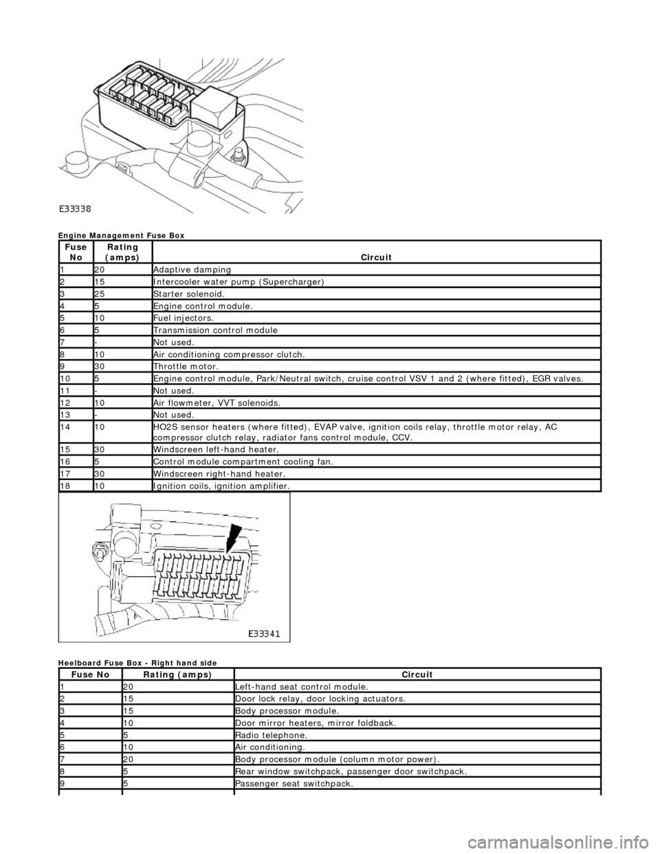
Engine Management Fuse Box
Heelboard Fuse Box - Right hand side
Fuse NoRating
(amps)Circuit
120Adaptive damping
215Intercooler water pump (Supercharger)
325Starter solenoid.
45Engine control module.
510Fuel injectors.
65Transmission control module
7-Not used.
810Air conditioning compressor clutch.
930Throttle motor.
105Engine control module, Park/Neutr al switch, cruise control VSV 1 and 2 (where fitted), EGR valves.
11-Not used.
1210Air flowmeter, VVT solenoids.
13-Not used.
1410HO2S sensor heaters (where fitted ), EVAP valve, ignition coils relay, throttle motor relay, AC
compressor clutch relay, radi ator fans control module, CCV.
1530Windscreen left-hand heater.
165Control module compartment cooling fan.
1730Windscreen right-hand heater.
1810Ignition coils, ignition amplifier.
Fuse NoRating (amps)Circuit
120Left-hand seat control module.
215Door lock relay, door locking actuators.
315Body processor module.
410Door mirror heaters, mirror foldback.
55Radio telephone.
610Air conditioning.
720Body processor module (column motor power).
85Rear window switchpack, passenger door switchpack.
95Passenger seat switchpack.
Page 1977 of 2490
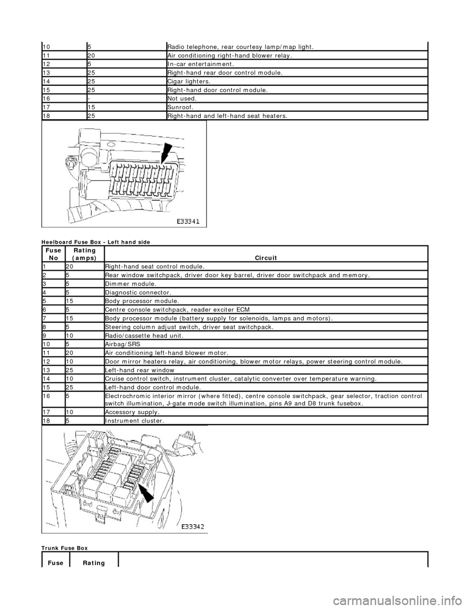
Heelboard Fuse Box - Left hand side
Trunk Fuse Box
105Radio telephone, rear courtesy lamp/map light.
1120Air conditioning right-hand blower relay.
125In-car entertainment.
1325Right-hand rear door control module.
1425Cigar lighters.
1525Right-hand door control module.
16-Not used.
1715Sunroof.
1825Right-hand and left-hand seat heaters.
Fuse NoRating
(amps)Circuit
120Right-hand seat control module.
25Rear window switchpack, driver door key ba rrel, driver door switchpack and memory.
35Dimmer module.
45Diagnostic connector.
515Body processor module.
65Centre console switchpack, reader exciter ECM
715Body processor module (battery supply for solenoids, lamps and motors).
85Steering column adjust switch, driver seat switchpack.
910Radio/cassette head unit.
105Airbag/SRS
1120Air conditioning left-hand blower motor.
1210Door mirror heaters relay, air conditioning, blow er motor relays, power steering control module.
1325Left-hand rear window
1410Cruise control switch, instrument cluster, catalytic converter over temperature warning.
1525Left-hand door control module.
165Electrochromic interior mirror (where fitted), centre console switchpack, gear selector, traction control
switch illumination, J-gate mode switch illumination, pins A9 and D8 trunk fusebox.
1710Accessory supply.
185Instrument cluster.
Fuse Rating
Page 1985 of 2490
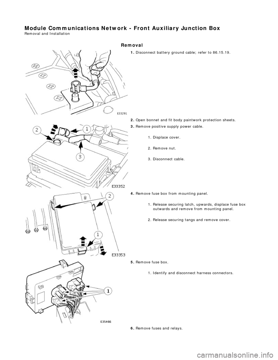
Module Communications Network - Front Auxiliary Junction Box
Removal and Installation
Removal
1. Disconnect battery ground cable; refer to 86.15.19.
2. Open bonnet and fit body pa intwork protection sheets.
3. Remove positive supply power cable.
1. Displace cover.
2. Remove nut.
3. Disconnect cable.
4. Remove fuse box fro m mounting panel.
1. Release securing latch, upwards, displace fuse box
outwards and remove from mounting panel.
2. Release securing tangs and remove cover.
5. Remove fuse box.
1. Identify and disconne ct harness connectors.
6. Remove fuses and relays.
Page 1987 of 2490
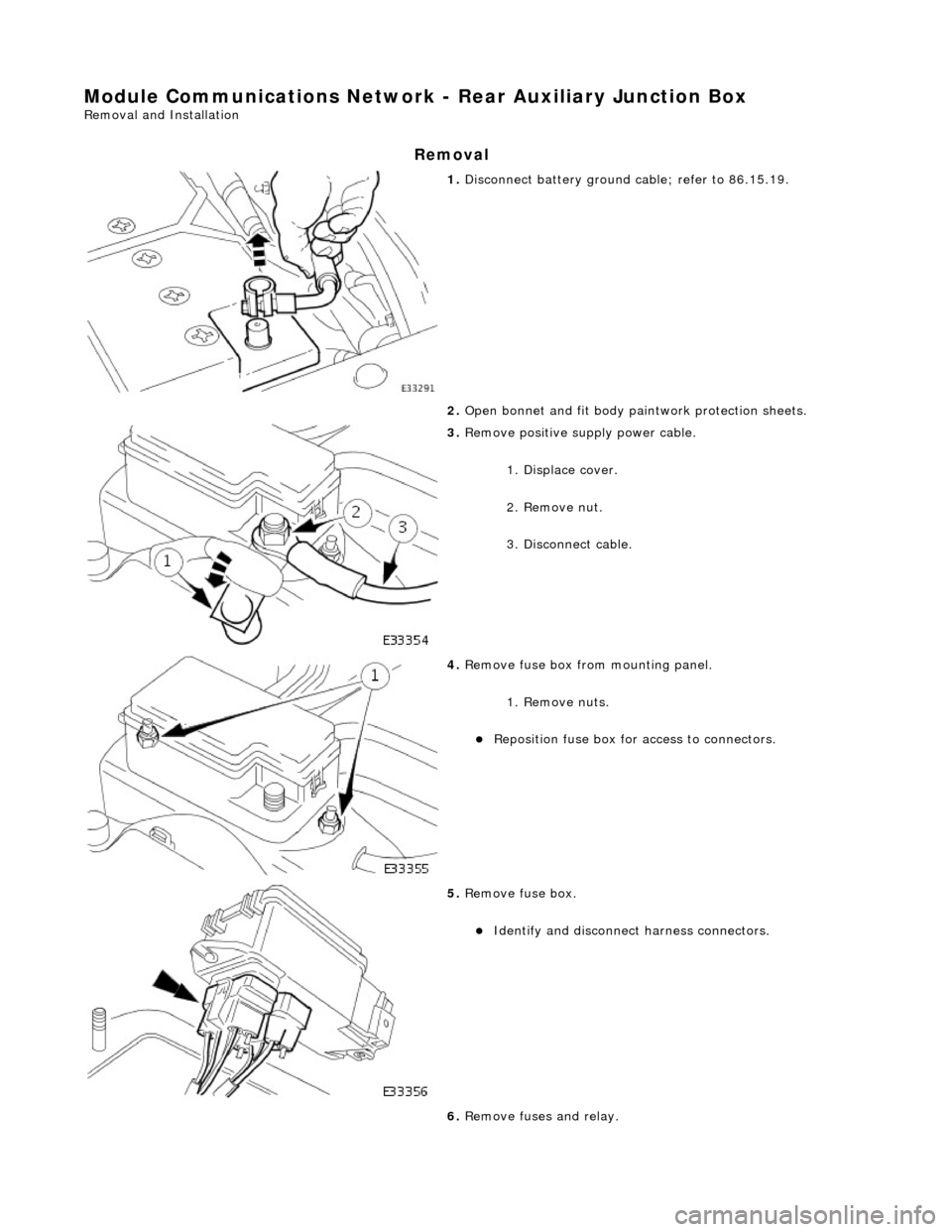
Module Communications Network - Rear Auxiliary Junction Box
Removal and Installation
Removal
1. Disconnect battery ground cable; refer to 86.15.19.
2. Open bonnet and fit body pa intwork protection sheets.
3. Remove positive supply power cable.
1. Displace cover.
2. Remove nut.
3. Disconnect cable.
4. Remove fuse box fro m mounting panel.
1. Remove nuts.
Reposition fuse box for access to connectors.
5. Remove fuse box.
Identify and disconnect harness connectors.
6. Remove fuses and relay.
Page 2006 of 2490

Multifunction Electronic Modules - Module Controlled Functions
Description and Operation
Body Processor Module (BPM)
ItemPart NumberDescription
1—Body Processor Module
2—Front Door Control Module
3—Rear Door Control Module
4—Roof Console Switch Module
5—Center Console Switch Module