body JAGUAR X308 1998 2.G Workshop Manual
[x] Cancel search | Manufacturer: JAGUAR, Model Year: 1998, Model line: X308, Model: JAGUAR X308 1998 2.GPages: 2490, PDF Size: 69.81 MB
Page 1161 of 2490
E
vaporative Emissions - Evaporative Emissions
D
iagnosis and Testing
Prelim
inary Inspection
1.
1. Vis
ually inspect for obvious signs of mechanical or electrical damage.
V
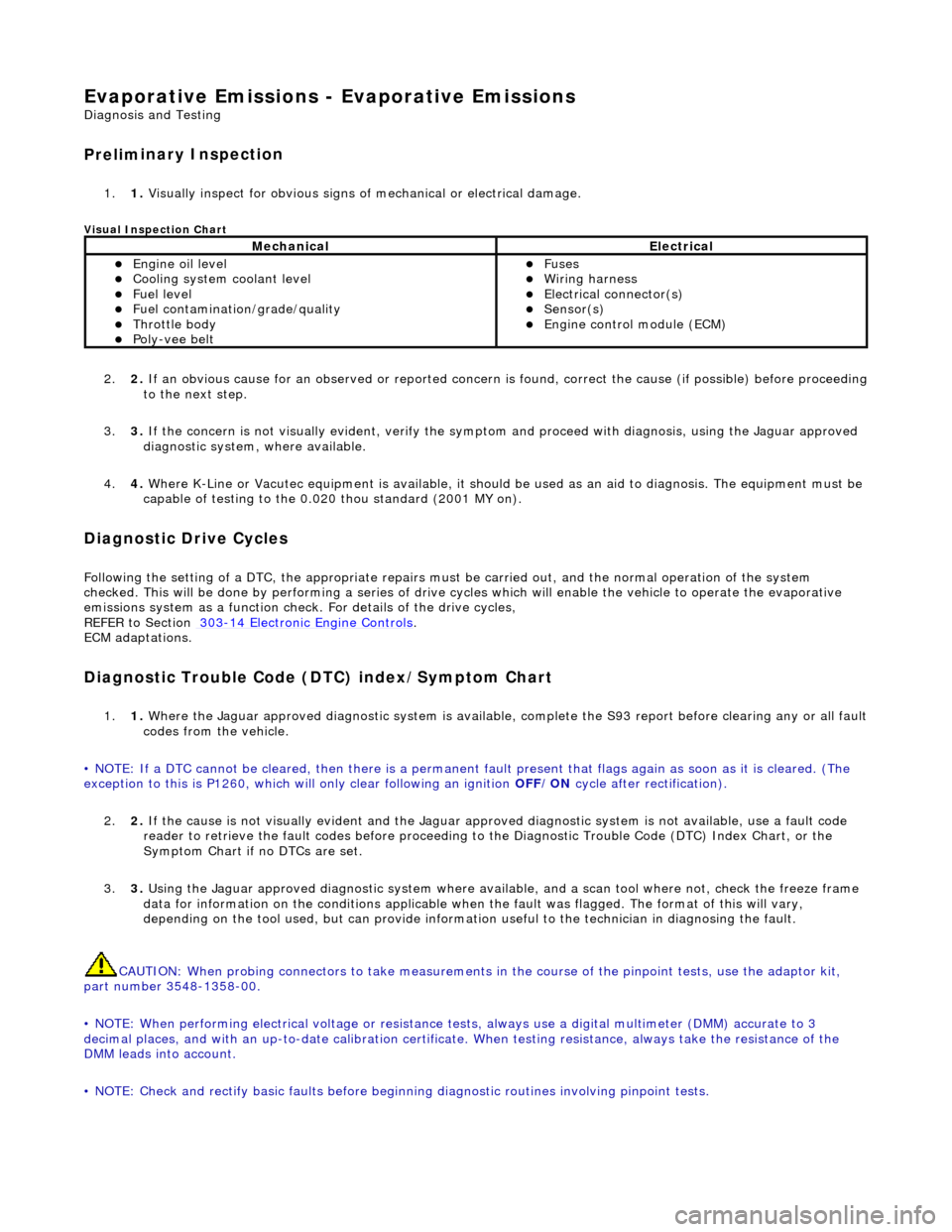
isual Inspection Chart
2.
2. If
an obvious cause for an observed or
reported concern is found, correct th e cause (if possible) before proceeding
to the next step.
3. 3. If the concern is not visually evident, verify the symptom and proceed with diagnosis, using the Jaguar approved
diagnostic system, where available.
4. 4. Where K-Line or Vacutec equipment is available, it should be used as an aid to diagnosis. The equipment must be
capable of testing to the 0.020 thou standard (2001 MY on).
Diagnostic Drive Cycles
Following th
e setting of a DTC, the appropriate repairs must
be carried out, and the normal operation of the system
checked. This will be done by performing a series of drive cycles which will enable the vehicle to operate the evaporative
emissions system as a function check. For details of the drive cycles,
REFER to Section 303
-1
4 Electronic Engine Controls
.
ECM adapt
ations.
Diagnostic Trouble Code
(D
TC) index/Symptom Chart
1.
1. Wh
ere the Jaguar approved diagnostic sy
stem is available, complete the S93 report before clearing any or all fault
codes from the vehicle.
• NOTE: If a DTC cannot be cleared, then there is a permanent fault present that flag s again as soon as it is cleared. (The
exception to this is P1260, which will only clear following an ignition OFF/ON cycle after rectification).
2. 2. If the cause is not visually evident and the Jaguar approv ed diagnostic system is not available, use a fault code
reader to retrieve the fault codes be fore proceeding to the Diagnostic Trou ble Code (DTC) Index Chart, or the
Symptom Chart if no DTCs are set.
3. 3. Using the Jaguar approved diagnostic system where available, and a scan tool where not, check the freeze frame
data for information on the conditions applicable when the fault was flagged. The format of this will vary,
depending on the tool used, but can pr ovide information useful to the technician in diagnosing the fault.
CAUTION: When probing connectors to take measurements in the course of the pinpoint tests, use the adaptor kit,
part number 3548-1358-00.
• NOTE: When performing electrical voltag e or resistance tests, always use a digital multimeter (DMM) accurate to 3
decimal places, and with an up-t o-date calibration certificate. When testing resistance, always take the resistance of the
DMM leads into account.
• NOTE: Check and rectify basic faults before beginning diagnostic ro utines involving pinpoint tests.
MechanicalElectrical
Engi
ne oil level
Coo
ling system coolant level
Fue
l level
Fuel contaminatio
n
/grade/quality
Throttle body Poly
-vee belt
F
uses
W
iring harness
E
lectrical connector(s)
Sens
or(s)
Engine
control module (ECM)
Page 1167 of 2490
E
vaporative Emissions - Evap
orative Emission Canister
Re
moval and Installation
Remov
al
WARNING: B
EFORE PROCEEDING, IT IS ESSENTIAL THAT
THE WARNING NOTES GIVEN IN SECTION 100-00 (UNDER
THE HEADING 'SAFETY PRECAUTION S') ARE READ AND UNDERSTOOD.
I
nstallation
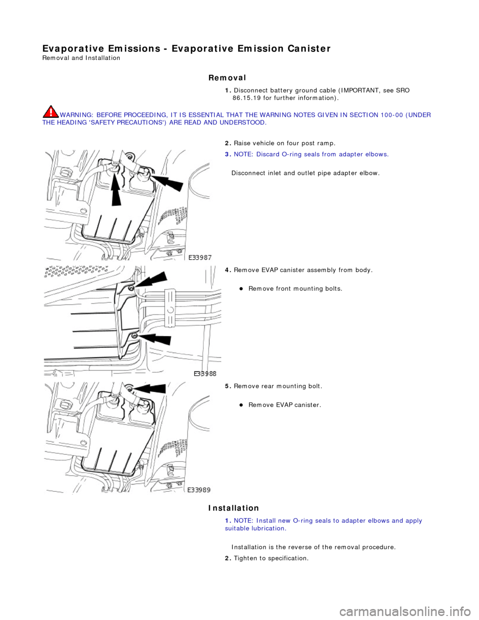
1.
Disc
onnect battery ground cable (IMPORTANT, see SRO
86.15.19 for further information).
2. R
aise vehicle on four post ramp.
3. N
OTE: Discard O-ring se
als from adapter elbows.
Disconnect inlet and outl et pipe adapter elbow.
4. R
emove EVAP canister assembly from body.
R
emove front mounting bolts.
5. Re
move rear mounting bolt.
Re
move EVAP canister.
1. NOTE: Install new O-ring seals to adapter elbows and apply
suitable lubrication.
Installation is th e reverse of the removal procedure.
2. Tighten to specification.
Page 1178 of 2490

Throttle Position (TP) Sensor
Location
P
arts List
sen
d
s the ECM a signal indica
ting throttle plate angle
is
the main input to the ECM from the driver
i
s
a dual Hall effect devi
ce mounted on the motor en d of the throttle body
Two additional sensors are attached to the throttle body to provide additional feedback to the ECM: a mechanical guard
position sensor and an accelerator pedal position sensor.
Cam s
haft Position (CMP) Sensor
sen
d
s the ECM a signal indicating camshaft po
sition for fuel synchronization purposes
is
a variable reluctance device mounted on bank 2 cylinder side face
generates a signal when the ri
ng
fitted to the bank 2 inlet
camshaft passes the sensor
Cranksha
ft Position (CKP) Sensor
i
s
a variable reluctance device
mounted on the engine oil pan
Ite
m
Par
t
Number
De
scr
iption
1—Acce
le
rator pedal and mechanic
al guard position sensors
2—Throttle
(blade)
position sensor
Page 1189 of 2490
E
lectronic Engine Controls -
Electronic Engine Controls
D
iagnosis and Testing
I
nspection and Verification
1.
1. Veri
fy the customer concern.
2. 2. Confirm which, if any, warning li ghts and/or messages were displayed on the instrument cluster.
• NOTE: If any warning lights and/or me ssages were displayed when the fault occurred, refer to the Driver Information
table for DTCs associated with the display, then to the DTC index table for possible sources and actions. Some warnings will
appear to clear when the ignition is cycl ed. This is often because the warning has flagged as a resu lt of one of the vehicle's
on-board diagnostic routines having run to detect the fault. If the same routine is not run when the ignition is switched ON,
the warning will not reflag until the routine does run. See the DTC summaries for drive cycle routines.
3. 3. Visually inspect for obvious signs of mechanical or electrical damage.
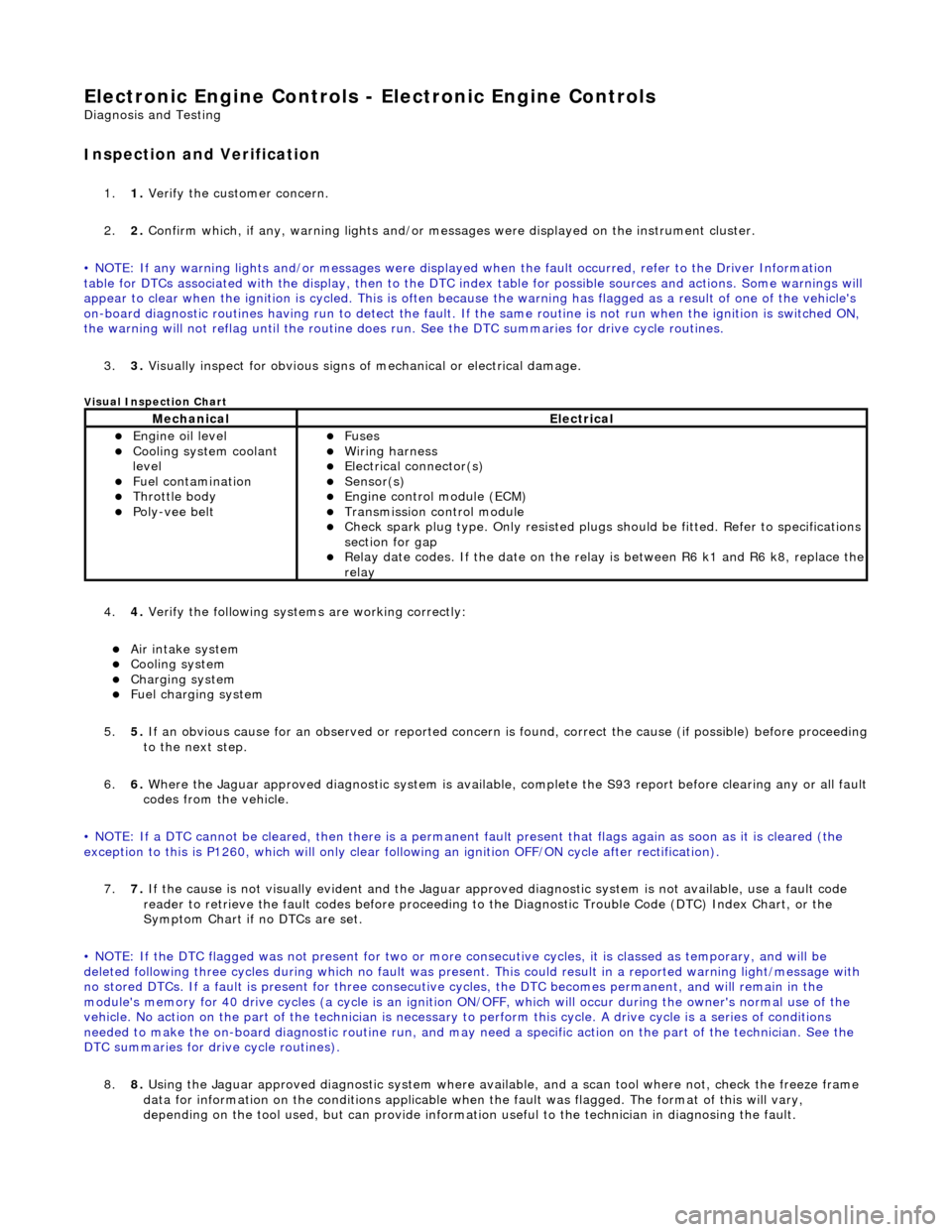
V
isual Inspection Chart
4.
4. Veri
fy the following syst
ems are working correctly:
Air in
take system
Coo
ling system
Charging system
F
uel charging system
5. 5. If an obvious cause for an observed or reported concern is found, correct the cause (if possible) before proceeding
to the next step.
6. 6. Where the Jaguar approved diagnostic sy stem is available, complete the S93 report before clearing any or all fault
codes from the vehicle.
• NOTE: If a DTC cannot be cleared, then there is a permanent fault present that flag s again as soon as it is cleared (the
exception to this is P1260, which will only clear following an ignition OFF/ON cycle after rectification).
7. 7. If the cause is not visually evident and the Jaguar approv ed diagnostic system is not available, use a fault code
reader to retrieve the fault codes be fore proceeding to the Diagnostic Trou ble Code (DTC) Index Chart, or the
Symptom Chart if no DTCs are set.
• NOTE: If the DTC flagged was not present for two or more co nsecutive cycles, it is classed as temporary, and will be
deleted following three cycl es during which no fault was present. This could result in a reported wa rning light/message with
no stored DTCs. If a fault is present for three consecutive cycles, the DTC becomes permanent, and will remain in the
module's memory for 40 drive cycles (a cy cle is an ignition ON/OFF, which will occur during the owner's normal use of the
vehicle. No action on the part of the technician is necessary to perform this cycle. A drive cycle is a series of conditions
needed to make the on-board diagnostic ro utine run, and may need a specific action on the part of the technician. See the
DTC summaries for driv e cycle routines).
8. 8. Using the Jaguar approved diagnostic system where available, and a scan tool where not, check the freeze frame
data for information on the conditions applicable when the fault was flagged. The format of this will vary,
dependin
g o
n the tool used, but can provide information useful to the technician in dia
gnos
in
g th
e fault.
MechanicalElectrical
Engi
ne oil level
Coo
ling system coolant
level
Fuel contamination
Throttle body Poly
-vee belt
F
uses
W
iring harness
E
lectrical connector(s)
Sens
or(s)
Engine
control module (ECM)
Tran
smission control module
Check spark plu
g type. Only re
sisted plugs should be fitted. Refer to specifications
section for gap
Relay date codes.
If the date on the rela
y is between R6 k1 and R6 k8, replace the
relay
Page 1201 of 2490

leak
/blockage
EVAP valve failure
P0444Evaporati
ve emissions system
(EVAP) valve circuit open circuit
EVAP t
o ECM drive circuit open
circuit or high resistance
EVAP failu
re
F
or evaporative emissions pinpoint
tests,
REFER to Section 303
-1
3 Evaporative
Emiss
ions
.
P0445Evaporati
ve emissions system
(EVAP) valve circuit short circuit
E
VAP to ECM drive circuit short
circuit to ground
EVAP failu
re
F
or evaporative emissions pinpoint
tests,
REFER to Section 303
-1
3 Evaporative
Emiss
ions
.
P0447Cani
ster close valve (CCV) circuit
open circuit
CCV to ECM
drive circuit open
circuit, high resi stance or short
circuit to ground
EVAP failu
re
F
or evaporative emissions pinpoint
tests,
REFER to Section 303
-1
3 Evaporative
Emiss
ions
.
P0448Cani
ster close valve (CCV) circuit
short circuit
CCV to
ECM drive circuit short
circuit to high voltage
CCV failure
F
or evaporative emissions pinpoint
tests,
REFER to Section 303
-1
3 Evaporative
Emiss
ions
.
P0452F
uel tank pressure (FTP) sensor
circuit low voltage
FTP
sensor disconnected
FTP
sensor to ECM sense circuit
open circuit or short circuit to
ground
FTP sen
sor to ECM power supply
circuit open circuit or short circuit
to ground
F
TP sensor failure
F
or evaporative emissions pinpoint
tests,
REFER to Section 303
-1
3 Evaporative
Emiss
ions
.
P0453F
uel tank pressure (FTP) sensor
circuit high voltage
FTP
sensor to ECM signal ground
circuit open circuit
F
TP sensor to ECM wiring (supply,
sense, signal, ground) short circuit
to each other
FTP
sensor to ECM sense circuit
short circuit to high voltage
F
TP sensor failure
F
or evaporative emissions pinpoint
tests,
REFER to Section 303
-1
3 Evaporative
Emiss
ions
.
P0460Fue
l level sense signal
performance
Fue
l level sensor
to instrument
cluster circuits in termittent short or
open circuit
F
uel level sensor failure
Instrument cluster
faul
t (incorrect
fuel level data)
F
or fuel level sensor
circuit tests,
REFER to Section 303
-04
Fuel
Charging and Con
trols
.
P0506Idl
e rpm lower than expected
Ai
r intake blockage
Acce
ssory drive overload
(defective/siezed component)
Thr
ottle valve stuck closed
Throttl
e assembly failure
Chec
k the air intake system.
REFER to Section 303
-1
2 Intake Air
Distribu
tion and Filtering
.
Check t
he accessory drive
components,
REFER to Section 303
-0
5 Accessory
Dr
ive
.
F
or throttle body information,
REFER to Section 303
-04
Fuel
Charging and Con
trols
.
P0507Idle rpm
higher than expected
Inta
ke air leak between MAF
sensor and throttle
Inta
ke air leak between throttle
and engine
Engine
breather leak
Cruis
e (speed) control vacuum
failure
Thr
ottle valve stuck open
Throttl
e assembly failure
Chec
k the air intake system.
REFER to Section 303
-1
2 Intake Air
Distribu
tion and Filtering
.
Chec
k the engine breather system,
REFER to Section 303
-08
Engine
Emissi
on Control
.
F
or cruise (speed) control information,
REFER to Section 310
-03
Speed
Control.
F
or throttle body information,
REFER to Section 303
-04
Fuel
Charging and Con
trols
.
P0560Vehicle voltage
malfunction
ECM battery
power supply open
circuit, high resistance
F
or ECM power supply circuit tests,
GO to Pinpoint Test AD.
.
P0566Cruise (speed) contr
ol
CANCEL
switch ON fault
Cru
ise (speed) control switches
internal steering wheel short circuit
to ground
For cru
ise (speed) control circuit tests,
REFER to Section 310
-03
Speed
Page 1203 of 2490

P1122Acce
lerator pedal position (APP)
sensor circuit 'A' low voltage
A
PP sensor to ECM sense circuit
'A' (sensor pin 5) open circuit or
high resistance
Sensor power su
pply fault
APP s
ensor failure
For APP
sensor circuit tests,GO to
Pinpoint Test R.
, andG
O to Pinpoint
Test S.
.
P1123Acce
lerator pedal position (APP)
sensor circuit 'A' high voltage
A
PP sensor to ECM sense circuit
'A' (sensor pin 5) short circuit to
high voltage
APP s
ensor failure
For APP
sensor circuit tests, GO to
Pinpoint Test R.
, and G
O to Pinpoint
Test S.
.
P1221Acce
lerator pedal position (APP)
sensor circuit 'B'
range/performance
A
PP sensor to ECM sense circuit
'B' (sensor pin 3) open circuit,
short circuit or high resistance
Sensor power su
pply fault
Sensor r
eference ground fault
APP s
ensor failure
For APP
sensor circuit tests,GO to
Pinpoint Test R.
, andG
O to Pinpoint
Test S.
.
P1222Acce
lerator pedal position (APP)
sensor circuit 'B' low voltage
A
PP sensor to ECM sense circuit
'B' (sensor pin 3) open circuit or
high resistance
Sensor power su
pply fault
APP s
ensor failure
For APP
sensor circuit tests,GO to
Pinpoint Test R.
, andG
O to Pinpoint
Test S.
.
P1223Acce
lerator pedal position (APP)
sensor circuit 'B' high voltage
A
PP sensor to ECM sense circuit
'B' (sensor pin 3) short circuit to
high voltage
APP s
ensor failure
For APP
sensor circuit tests,GO to
Pinpoint Test R.
, andG
O to Pinpoint
Test S.
.
P1224Throttl
e control position error
Thro
ttle position adaptations not
performed after ba ttery disconnect
TP se
nsor disconnected
TP se
nsor to ECM sense circuits
open circuit, hi gh resistance
Throttl
e motor power relay failure
Throttl
e motor power relay to ECM
circuit fault
Throttl
e motor power relay power
supply open circuit
ECM ground circuit faul
t (relay coil
drive)
Th
rottle motor to ECM drive circuits
open circuit, short circuit, high
resistance
Throttl
e motor failure
Throttl
e assembly failure
Carry
out throttle adaptation
procedure. For TP sensor circuit
tests,GO to Pinpoint Test D.
, andG
O
to Pinpoint Test K.
. F
or throttle motor
circuit tests,GO to Pinpoint Test T.
.
F
or throttle body information,
REFER to Section 303
-04
Fuel
Charging and Con
trols
.
P1226Mechanica
l guard sensor
range/performance
Mechanica
l guard sensor to ECM
sense circuit open circuit, short
circuit or high resistance
Sensor power su
pply fault
Sensor r
eference ground fault
Mechanica
l guard sensor failure
Mechanica
l guard actuator
seized/spring broken
For mech
anical guard circuit tests,GO
to Pinpoint Test U.
. F
or sensor power
supply circuit tests,GO to Pinpoint
Test V.
. F
or sensor ground circuit
tests,GO to Pinpoint Test W.
. For
throttle body i
nformation,
REFER to Section 303
-04
Fuel
Charging and Con
trols
.
P1227Mechanica
l guard sensor circuit
low voltage
Mechanica
l guard sensor to ECM
sense circuit open circuit or high
resistance
Sensor power su
pply fault
Mechanica
l guard sensor failure
For mech
anical guard circuit tests,GO
to Pinpoint Test U.
. F
or sensor power
supply circuit tests,GO to Pinpoint
Test V.
. F
or throttle body
information,
REFER to Section 303
-04
Fuel
Charging and Con
trols
.
P1228Mechanica
l guard sensor circuit
high voltage
Mechanica
l guard sensor to ECM
sense circuit short circuit to high
voltage
Mechanica
l guard sensor failure
For mech
anical guard circuit tests,GO
to Pinpoint Test U.
. F
or throttle body
information,
REFER to Section 303
-04
Fuel
Charging and Con
trols
.
P1229Throttl
e motor control circuit
mallfunction
Throttl
e motor disconnected
Th
rottle motor to ECM drive circuits
short circuit or open circuit
Throttl
e motor failure
Fo
r throttle motor circuit tests,GO to
Pinpoint Test T.
.
P1230Fue
l pump relay malfunction.
NOTE. This DTC covers the S/C
system fuel pump 1
F
uel pump relay failure
F
uel pump to ECM circuit fault
F
uel pump relay coil power supply
F
or fuel pump relay circuit tests,
REFER to Section 303
-04
Fuel
Charging and Con
trols
.
Page 1204 of 2490

op
en circuit
ECM ground circuit faul
t (relay coil
drive)
P1235Vacuu m
switching valve (VSV) 1
circuit range/ performance
(mechanical guard position)
Vac u
um leak/blockage between the
throttle elbow and the throttle
vacuum actuator
Vacuu m
actuator failure
Mechanica
l
guard actuator
seized/spring broken
Carr y out mechanical checks
for
vacuum leak/blockag e, failed vacuum
actuator, and broken /siezed actuator
spring.
P1236Vacuu m
switching valve (VSV) 1
(vacuum) circuit failure
VSV 1 disconne cted
VSV 1 to ECM drive circu
i
t high
resistance, open circuit or short
circuit
VSV 1 powe r supply open
circuit
VSV 1 failu
r
e
For VSV tests,
REF
ER to Section 310
-03
Sp
eed
Control.
P1237Vacuu
m
switching valve (VSV) 2
(atmosphere) circuit failure
VSV 2 disconne cted
VSV 2 to ECM drive circu
i
t high
resistance, open circuit or short
circuit
VSV 2 power supply open
circuit
VSV 2 failu
r
e
For VSV tests,
REF
ER to Section 310
-03
Sp
eed
Control.
P1238Vacuu
m
switching valve (VSV) 3
(release) circuit failure
VSV 3 disconne cted
VSV 3 to ECM drive circu
i
t high
resistance, open circuit or short
circuit
VSV 3 powe r supply open
circuit
VSV 3 failu
r
e
For VSV tests,
REF
ER to Section 310
-03
Sp
eed
Control.
P1240Sensor r
e
fere
nce voltage
malfunction (throttle sensors, fuel
tank pressure se nsor) (ECM pins
EM10-21; EM11-8)
ECM t o
sensors reference voltage
short circuit to ground, short circuit
to high voltage, op en circuit, high
resistance
TP sensor , pedal position and
mechan
ical guard sensor(s), fuel
tank pressure sens or failure(s)
Fo
r sensor reference voltage circuit
tests,GO to Pinpoint Test V.
.
P1241Sensor re
ferenc
e voltage low
(throttle sensors, fuel tank
pressure sensor) (ECM pins EM10-
21; EM11-8)
ECM t o
sensors reference voltage
short circuit to ground
TP sensor , APP
and mechanical
guard sensor(s), fuel tank pressure
sensor failure(s)
F o
r sensor reference voltage circuit
tests,GO to Pinpoint Test V.
.
P1242Sensor re
ferenc
e voltage high
(throttle sensors, fuel tank
pressure sensor) (ECM pins EM10-
21; EM11-8)
ECM t o
sensors reference voltage
circuit open circuit, high resistance,
short circuit to high voltage
TP sensor , APP
and mechanical
guard sensor(s), fuel tank pressure
sensor failure(s)
F o
r sensor reference voltage circuit
tests,GO to Pinpoint Test V.
.
P1243Sensor re
ference ground
malfunction (throttle sensors, fuel
tank pressure sensor, ECT sensor,
IAT sensor, IAT sensor 2) (ECM
pins EM10-20; EM11-12)
ECM t o
sensors reference ground
circuit open circuit, high resistance
Throttle sensors, fuel
tank pressure
sensor, ECT sensor, IAT sensor,
IAT sensor 2 failures
F o
r sensor reference ground circuit
tests,GO to Pinpoint Test W.
.
P1245Engine crank signal low voltage Starter relay coi
l to ECM/BPM
circuit open circuit
For en gin
e crank circuit tests,GO to
Pinpoint Test X.
.
P1246Engine crank signal high voltage Starter relay coi
l to ECM/BPM
circuit short circuit to B+ voltage
B P
M failure
For en
gin
e crank circuit tests,GO to
Pinpoint Test X.
.
P1250Engine load
malfunction
Air in
take leak
Engine breath
er leak
TP sens
or circuit fault (DTC P0121)
Throttle
valve spring failure
Check air i
ntake system for leaks,
REFER to Section 303
-12
Intake Air
Distribution and Filterin
g
.
Check engi
ne breather system for
leaks,
REFER to Section 303
-08 En
gine
Emissi
on Control.
Se e
pinpoint test for P0121. For
throttle body information,
REFER to Section 303
-04 Fu
el
Charging and Con
t
rols
.
P1251Thr
o
ttle position malfunction
(engine off)
TP sensor to ECM wiri
ng open
circuit or high resistance
F o
r TP sensor circ
uit tests,GO to
Pinpoint Test D.
, andGO to Pinpoint
Page 1205 of 2490
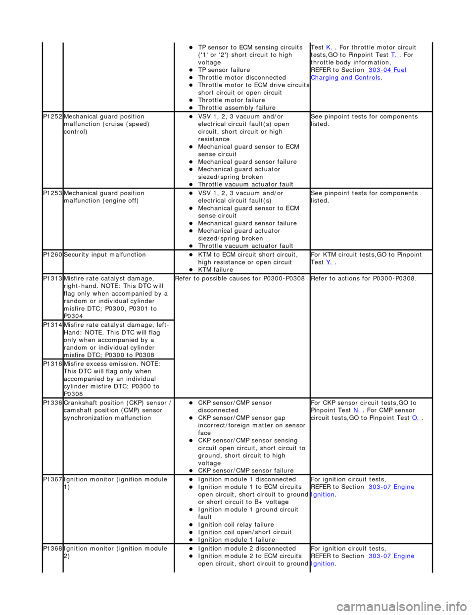
TP se
nsor to ECM sensing circuits
('1' or '2') short circuit to high
voltage
TP sensor
failure
Throttl
e motor disconnected
Th
rottle motor to ECM drive circuits
short circuit or open circuit
Throttl
e motor failure
Throttl
e assembly failure
Test
K. . F
or throttle motor circuit
tests,GO to Pinpoint Test T.
. For
throttle body i
nformation,
REFER to Section 303
-04
Fuel
Charging and Con
trols
.
P1252Mec
hanical gu
ard position
malfunction (cruise (speed)
control)
VSV 1, 2, 3 v
acuum and/or
electrical circuit fault(s) open
circuit, short circuit or high
resistance
Mechanica
l guard sensor to ECM
sense circuit
Mechanica
l guard sensor failure
Mechanica
l guard actuator
siezed/spring broken
Throttl
e vacuum actuator fault
Se
e pinpoint tests for components
listed.
P1253Mec
hanical gu
ard position
malfunction (engine off)
VSV 1, 2, 3 v
acuum and/or
electrical circuit fault(s)
Mechanica
l guard sensor to ECM
sense circuit
Mechanica
l guard sensor failure
Mechanica
l guard actuator
siezed/spring broken
Throttl
e vacuum actuator fault
Se
e pinpoint tests for components
listed.
P1260Se
curity input malfunction
K
TM to ECM circuit short circuit,
high resistance or open circuit
KTM failu
re
F
or KTM circuit tests,GO to Pinpoint
Test Y.
.
P1313M
isfire rate catalyst damage,
right-hand. NOTE: This DTC will
flag only when accompanied by a
random or individual cylinder
misfire DTC; P0300, P0301 to
P0304
R
efer to possible causes for P0300-P0308
R
efer to actions for P0300-P0308.
P1314Mi
sfire rate catalyst damage, left-
Hand: NOTE. This DTC will flag
only when accompanied by a
random or individual cylinder
misfire DTC; P0300 to P0308
P1316M
isfire excess emission. NOTE:
This DTC will flag only when
accompanied by an individual
cylinder misfire DTC; P0300 to
P0308
P1336Cranksh
aft position
(CKP) sensor /
camshaft position (CMP) sensor
synchronization malfunction
CKP s
ensor/CMP sensor
disconnected
CKP sensor/CM
P sensor gap
incorrect/foreign matter on sensor
face
CKP s
ensor/CMP sensor sensing
circuit open circuit, short circuit to
ground, short circuit to high
voltage
CKP s
ensor/CMP sensor failure
F
or CKP sensor circ
uit tests,GO to
Pinpoint Test N.
. For CM
P sensor
circuit tests,GO to Pinpoint Test O.
.
P1367Ignit
ion monitor (ignition module
1)
Ignition modu
le
1 disconnected
Ignition modul
e 1 to ECM circuits
open circuit, short circuit to ground
or short circuit to B+ voltage
Ignition modul
e 1 ground circuit
fault
Ignition coil
relay failure
Ignition coil
open/short circuit
Ignition modul
e 1 failure
F
or ignition circuit tests,
REFER to Section 303
-07
Engine
Ignition.
P1368Ignit
ion monitor (ignition module
2)
Ignition modu
le
2 disconnected
Ignition modul
e 2 to ECM circuits
open circuit, short circuit to ground
F
or ignition circuit tests,
REFER to Section 303
-07
Engine
Ignition.
Page 1207 of 2490
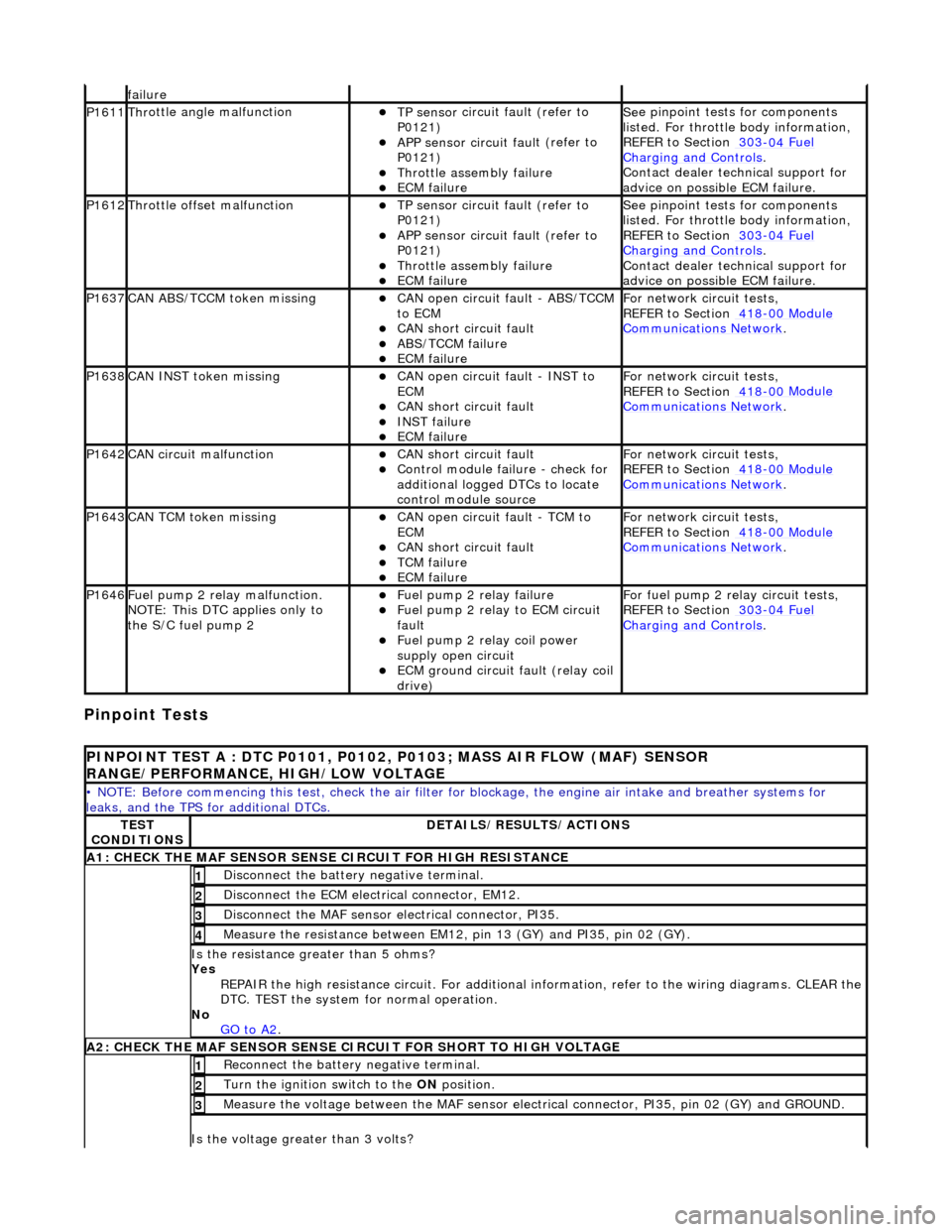
Pinpoint Tests
f
ailure
P1611Thr
ottle angle malfunction
TP sensor
circuit fault (refer to
P0121)
APP sensor circuit faul
t (refer to
P0121)
Throttl
e assembly failure
ECM failu
re
Se
e pinpoint tests for components
listed. For throttle body information,
REFER to Section 303
-04
Fuel
Charging and Con
trols
.
Contact deal
er technical support for
advice on possible ECM failure.
P1612Throttl
e offset malfunction
TP sensor
circuit fault (refer to
P0121)
APP sensor circuit faul
t (refer to
P0121)
Throttl
e assembly failure
ECM failu
re
Se
e pinpoint tests for components
listed. For throttle body information,
REFER to Section 303
-04
Fuel
Charging and Con
trols
.
Contact deal
er technical support for
advice on possible ECM failure.
P1637CAN AB
S/TCCM token missing
CAN
open circuit fault - ABS/TCCM
to ECM
CAN s
hort circuit fault
ABS/TCCM failu
re
ECM failu
re
F
or network circuit tests,
REFER to Section 418
-00
Module
Comm
unications Network
.
P1638CAN INST token missingCAN
open circuit fault - INST to
ECM
CAN s
hort circuit fault
INST
failure
ECM failu
re
F
or network circuit tests,
REFER to Section 418
-00
Module
Comm
unications Network
.
P1642CAN c
ircuit malfunction
CAN s
hort circuit fault
Control modul
e failure - check for
additional logged DTCs to locate
control module source
F
or network circuit tests,
REFER to Section 418
-00
Module
Comm
unications Network
.
P1643CAN TC
M token missing
CAN
open circuit fault - TCM to
ECM
CAN s
hort circuit fault
TCM failure
ECM failu
re
F
or network circuit tests,
REFER to Section 418
-00
Module
Comm
unications Network
.
P1646F
uel pump 2 relay malfunction.
NOTE: This DTC applies only to
the S/C fuel pump 2
F
uel pump 2 relay failure
F
uel pump 2 relay to ECM circuit
fault
F
uel pump 2 relay coil power
supply open circuit
ECM ground circuit faul
t (relay coil
drive)
F
or fuel pump 2 relay circuit tests,
REFER to Section 303
-04
Fuel
Charging and Con
trols
.
P
INPOINT TEST A : DTC P0101, P0102, P0103; MASS AIR FLOW (MAF) SENSOR
RANGE/PERFORMANCE, HIGH/LOW VOLTAGE
•
NOTE: Before commencing this
test, check the air filter for blockage, the engine air inta ke and breather systems for
leaks, and the TPS for additional DTCs.
TE
ST
CONDITIONS
D
ETAILS/RESULTS/ACTIONS
A1: CHECK
THE MAF SENSOR SENS
E CIRCUIT FOR HIGH RESISTANCE
Di
sconnect the battery negative terminal.
1
D
isconnect the ECM electrical connector, EM12.
2
Di
sconnect the MAF sensor electrical connector, PI35.
3
Meas
ure the resistance between EM12, pin 13 (GY) and PI35, pin 02 (GY).
4
Is th
e resistance greater than 5 ohms?
Yes REPAIR the high resistance circuit. For additional information, refer to the wiring diagrams. CLEAR the
DTC. TEST the system for normal operation.
No GO to A2
.
A2: CHECK
THE MAF SENSOR SENSE CI
RCUIT FOR SHORT TO HIGH VOLTAGE
R
econnect the battery negative terminal.
1
Turn the ignition swi
tch to the ON
position.
2
M
easure the voltage between the MAF sensor electrical connector, PI35, pin 02 (GY) and GROUND.
3
Is th
e voltage greater than 3 volts?
Page 1243 of 2490
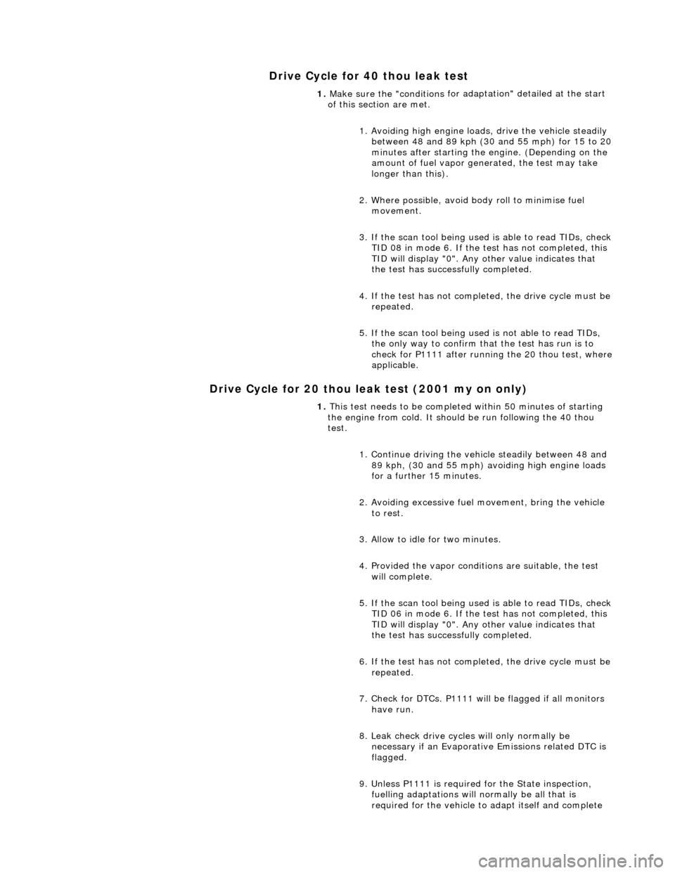
Drive Cycle for 40 thou leak test
Drive Cycle for 20 thou leak test (2001 my on only)
1. Make sure the "conditions
for ad
aptation" detailed at the start
of this section are met.
1. Avoiding high engine load s, drive the vehicle steadily
between 48 and 89 kph (30 and 55 mph) for 15 to 20
minutes after starting the engine. (Depending on the
amount of fuel vapor gene rated, the test may take
longer than this).
2. Where possible, avoid body roll to minimise fuel movement.
3. If the scan tool being used is able to read TIDs, check
TID 08 in mode 6. If the test has not completed, this
TID will display "0". Any other value indicates that
the test has successfully completed.
4. If the test has not completed, the drive cycle must be repeated.
5. If the scan tool being used is not able to read TIDs, the only way to confirm that the test has run is to
check for P1111 after running the 20 thou test, where
applicable.
1. This test needs to be completed within 50 minutes of starting
the engine from cold. It should be run following the 40 thou
test.
1. Continue driving the vehi cle steadily between 48 and
89 kph, (30 and 55 mph) avoiding high engine loads
for a further 15 minutes.
2. Avoiding excessive fuel movement, bring the vehicle to rest.
3. Allow to idle for two minutes.
4. Provided the vapor conditions are suitable, the test will complete.
5. If the scan tool being used is able to read TIDs, check
TID 06 in mode 6. If the test has not completed, this
TID will display "0". Any other value indicates that
the test has successfully completed.
6. If the test has not completed, the drive cycle must be repeated.
7. Check for DTCs. P1111 will be flagged if all monitors have run.
8. Leak check drive cycles will only normally be necessary if an Evaporative Emissions related DTC is
flagged.
9. Unless P1111 is required for the State inspection, fuelling adaptations will normally be all that is
required for the vehicle to adapt itself and complete