body JAGUAR X308 1998 2.G Workshop Manual
[x] Cancel search | Manufacturer: JAGUAR, Model Year: 1998, Model line: X308, Model: JAGUAR X308 1998 2.GPages: 2490, PDF Size: 69.81 MB
Page 1106 of 2490
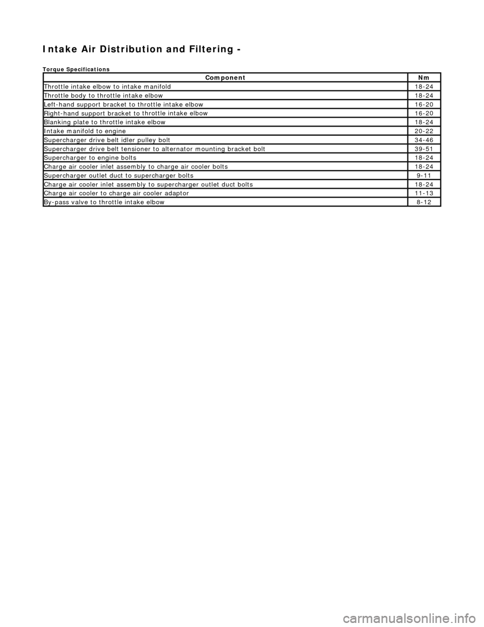
Intake Air Distribution and Filtering -
Torque Specificat
ions
Comp
onent
Nm
Thr
o
ttle intake elbow to intake manifold
18
-
24
Thro
tt
le body to throttle intake elbow
18
-
24
Left-hand support
bracket to
th
rottle intake elbow
16
-
20
Right-hand support
bracket to
throttle intake elbow
16
-
20
B
l
anking plate to throttle intake elbow
18
-
24
Inta
k
e manifold to engine
20
-
22
Supe
rcharger
drive belt idler pulley bolt
34
-
46
Supercharger
drive belt te
nsioner to alternator mounting bracket bolt
39
-
51
Supercharger
to eng
ine bolts
18
-
24
Charge air cooler in
let assembly to charge ai
r cooler bolts
18
-
24
Supercharger
outlet duct to supercharger bolts9-1
1
Charge air cooler in
let assembly to superchar
ger ou
tlet duct bolts
18-
24
Charge air cool
er to charge
air cooler adaptor
11
-
13
B
y
-pass valve to throttle intake elbow
8-
1
2
Page 1109 of 2490
P
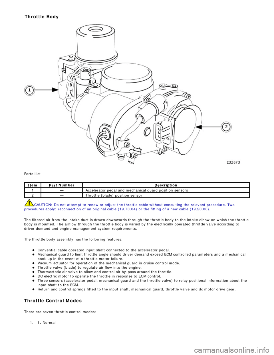
arts List
CAUTION: Do not attempt to renew or adjust the throttle cable without consulting the relevant procedure. Two
procedures apply: reconnection of an original cable (19.70.04) or the fitting of a new cable (19.20.06).
The filtered air from the intake duct is drawn downwards through the throttle body to the intake elbow on which the throttle
body is mounted. The airflow through the throttle body is vari ed by the electrically operated throttle valve according to
driver demand and engine mana gement system requirements.
The throttle body assembly has the following features:
Con
vential cable operated input shaft connected to the accelerator pedal.
M
echanical guard to limit throttle angl
e should driver demand exceed ECM co ntrolled parameters and a mechanical
back-up in the event of a throttle motor failure.
Vacuum actuator for operation of the mech anical guard in cru
ise control mode.
Thr
ottle valve (blade) to regula
te air flow into the engine.
Thermostatic air valve to allow and con
t
rol air by-pass around the throttle.
D
C electric motor to operate the thro
ttle in response to ECM control.
Three
sensors (accelerator pedal, mechan
ical guard and the throttle valve) to relay positional information about the
input shaft to the ECM.
R
eturn and control springs fitted to th
e input shaft, mechanical guard, thro ttle valve and dc motor drive gear.
Throttle Cont
rol Modes
There are seven throttle control
modes:
1. 1. Normal
It
em
Par
t Number
De
scription
1—Acce
lerator pedal and mechanic
al guard position sensors
2—Throttl
e (blade)
position sensor
Throttle Body
Page 1111 of 2490
the
intake elbow provide connections for vacuum actuators and are also used to redirect emissions into the engine.
On the right-hand side of the elbow a la rge diameter pipe connects to the brake servo. The smaller pipe provides a vacuum
feed to the fuel rail pressure regulator and throttle cruise control system. On the le ft-hand side of the elbow the front pipe
supplies vacuum control for the evaporative emissions system valves.
Emissions from the engine part load breather (bank 2) and pu rged fuel vapor from the EVAP valve are drawn via a common
T piece into the left-hand side of the intake elbow. Re-cir culated exhaust gas enters the intake elbow via the EGR valve
which is mounted directly on the rear of the elbow : where the EGR system is not used, a blanking plate is fitted.
The fuel system, throttle and emission control system s are described more fully in the relevant sections.
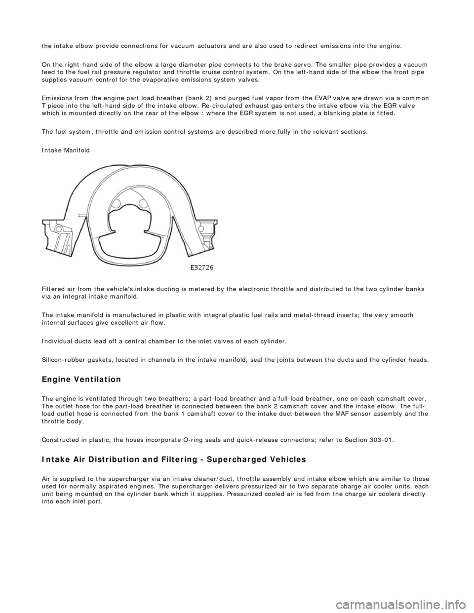
Intake Manifold
Filtered air from the vehicle's intake ducting is metered by th e electronic throttle and distributed to the two cylinder banks
via an integral intake manifold.
The intake manifold is manufactured in plastic with integral plastic fuel rails and metal-thread inserts; the very smooth
internal surfaces give excellent air flow.
Individual ducts lead off a central chamber to the inlet valves of each cylinder.
Silicon-rubber gaskets, loca ted in channels in the intake manifold, seal th e joints between the ducts and the cylinder heads.
Engine Ventilation
The e
ngine is ventilated through two brea
thers; a part-load breather and a full-load breather, one on each camshaft cover.
The outlet hose for the part-load breather is connected between the bank 2 camshaft cover and the intake elbow. The full-
load outlet hose is connected from the bank 1 camshaft cover to the intake duct between the MAF sensor assembly and the
throttle body.
Constructed in plastic, the hoses incorporate O-ring seal s and quick-release connectors; refer to Section 303-01.
I
ntake Air Distribution and Filtering - Supercharged Vehicles
Ai
r is supplied to the supercharger via an
intake cleaner/duct, throttle assembly and intake elbow which are similar to those
used for normally aspirated engines. The su percharger delivers pressurized air to two separate charge air cooler units, each
unit being mounted on the cy linder bank which it supplies. Pr essurized cooled air is fed from the charge air coolers directly
into each inlet port.
Page 1113 of 2490
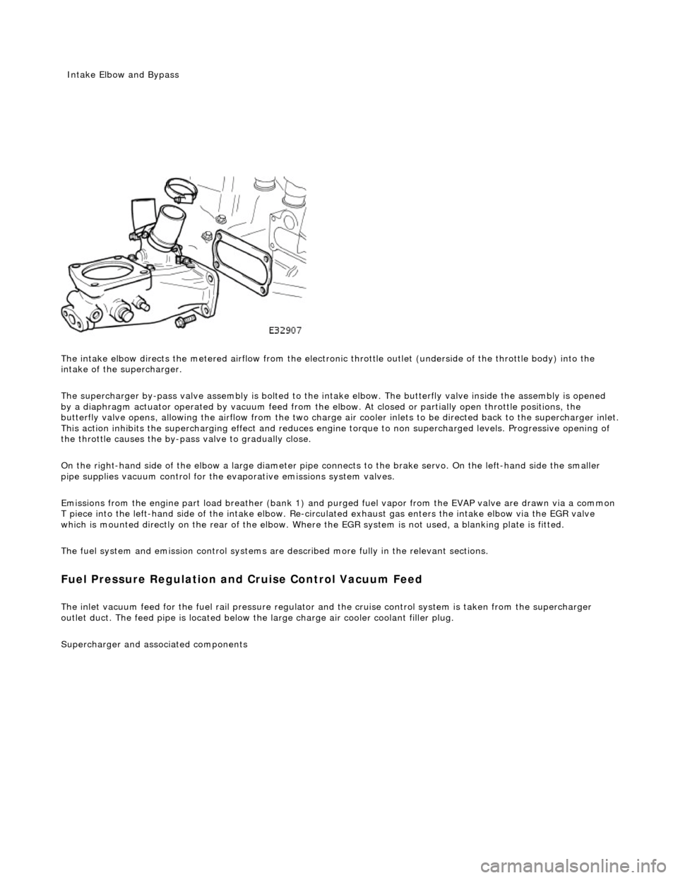
The intake elbow di
rects the metered airflow from the electronic throttle outlet (und
erside of the throttle body) into the
intake of the supercharger.
The supercharger by-pass valve assembly is bolted to the intake elbow. The butterfly valve inside the assembly is opened
by a diaphragm actuator operated by vacu um feed from the elbow. At closed or partially open throttle positions, the
butterfly valve opens, allowing th e airflow from the two charge air cooler inlets to be directed back to the supercharger inlet .
This action inhibits the supercharging e ffect and reduces engine torque to non supercharged levels. Progressive opening of
the throttle causes the by-pass valve to gradually close.
On the right-hand side of the elbow a la rge diameter pipe connects to the brake servo. On the left-hand side the smaller
pipe supplies vacuum control for the evaporative emissions system valves.
Emissions from the engine part load breather (bank 1) and pu rged fuel vapor from the EVAP valve are drawn via a common
T piece into the left-hand side of the intake elbow. Re-cir culated exhaust gas enters the intake elbow via the EGR valve
which is mounted directly on the rear of the elbow. Where the EGR system is not used, a blanking plate is fitted.
The fuel system and emission control systems are described more fully in the relevant sections.
Fuel Pressure Regula
tion and
Cruise Control Vacuum Feed
The inlet v
acuum feed fo
r the fuel rail pressure regula tor and the cruise control system is taken from the supercharger
outlet duct. The feed pipe is located below the large charge air cooler coolant filler plug.
Superchar
ger
and associated components
Inta
ke Elbow and Bypass
Page 1117 of 2490
I
nstallation
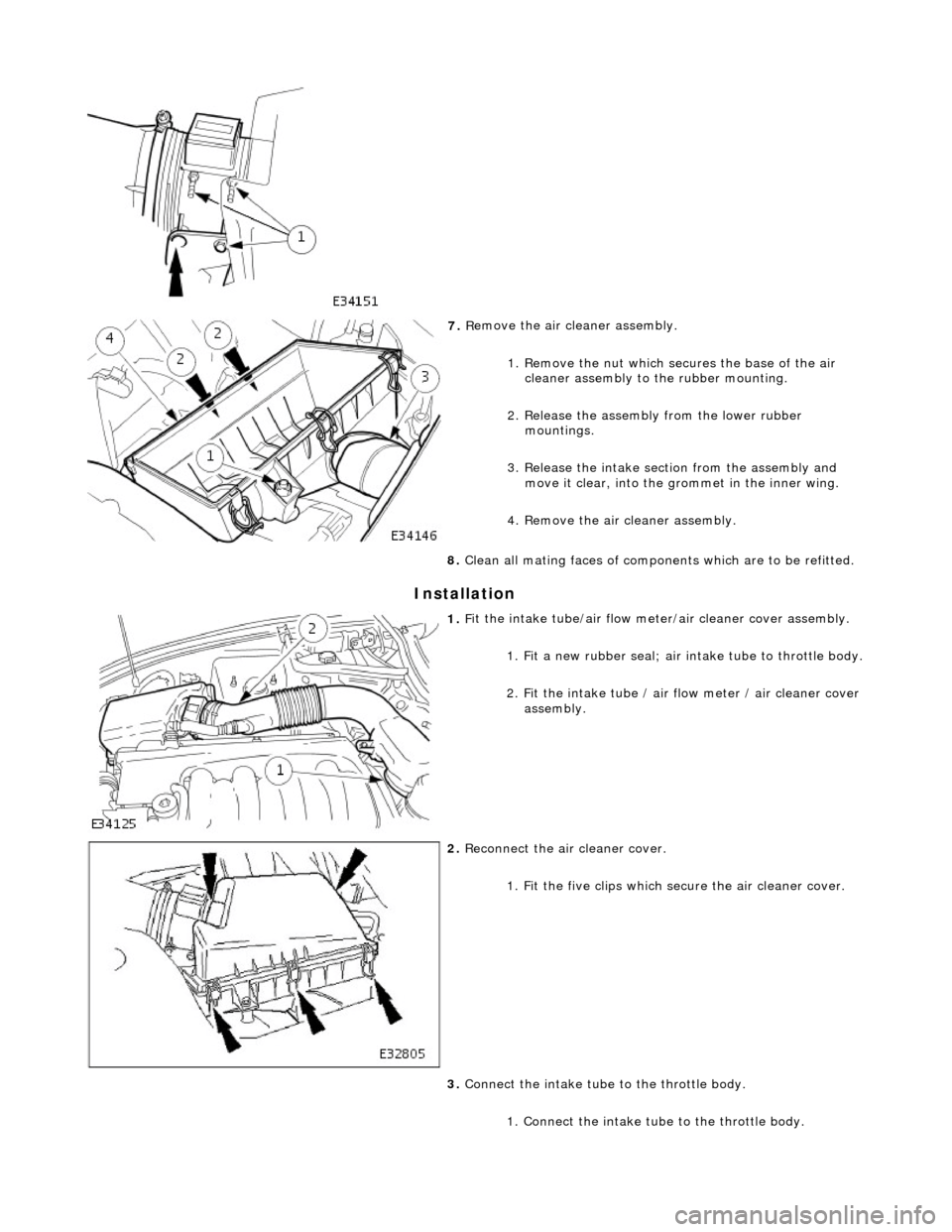
7.
R
emove the air cleaner assembly.
1. Remove the nut which se cures the base of the air
cleaner assembly to the rubber mounting.
2. Release the assembly from the lower rubber mountings.
3. Release the intake section from the assembly and move it clear, into the grommet in the inner wing.
4. Remove the air cleaner assembly.
8. Clean all mating faces of compon ents which are to be refitted.
1. F
it the intake tube/air flow meter/air cleaner cover assembly.
1. Fit a new rubber seal; air in take tube to throttle body.
2
. Fit the intake tube / air
flow meter / air cleaner cover
assembly.
2. R
econnect the air cleaner cover.
1. Fit the five clips which secure the air cleaner cover.
3. Connect the intake tube to the throttle body.
1. Connect the intake tube to the throttle body.
Page 1118 of 2490
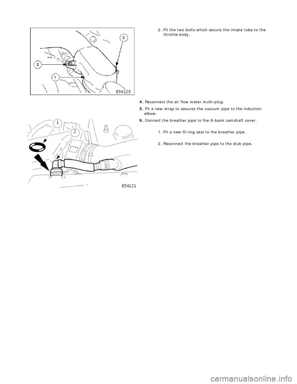
2. Fi
t the two bolts which secure the intake tube to the
throttle body.
4. Reconnect the air flow meter multi-plug.
5. Fit a new strap to secures the vacuum pipe to the induction
elbow.
6. Connect the breather pipe to
the A-bank camshaft cover.
1. Fit a new O-ring seal to the breather pipe.
2. Reconnect the breather pipe to the stub pipe.
Page 1119 of 2490
Intake Air Distribution and Filtering - Air Cleaner Element
Re
moval and Installation
Remov
al
Installation
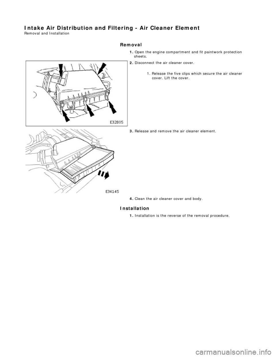
1.
O
pen the engine compartment and fit paintwork protection
sheets.
2. Di
sconnect the air cleaner cover.
1. Release the five clips which secure the air cleaner cover. Lift the cover.
3. R
elease and remove the air cleaner element.
4. Clean the air cleaner cover and body.
1. Installation is th e reverse of the re moval procedure.
Page 1120 of 2490
Intake Air Distribution and Filtering - Charge Air Cooler LH
Remo
val and Installation
Remov
a
l
Installation
1. Disc onne
ct battery ground cable (IMPORTANT, see SRO
86.15.19 for further information).
2. Drain radiator coolant; refer to 26.10.01.
3. Remove air cleaner cover / intake assembly; refer to 19.10.30.
4. Remove throttle body; refer to 19.70.04.
5. Remove exhaust gas re-circulation valve (EGR) if installed;
refer to 17.45.01.
6. Remove throttle intake elbo w; refer to (SC) 19.70.28.
7. Remove supercharger outlet duct; refer to 18.50.16.
8. Remove coolant outlet pipe; refe r to operation (SC) 26.31.08.
9. Remove supercharger drive belt; refer to 18.50.08.
10. Remove supercharger; refer to operation 18.50.15.
11. Detach engine harness retaining clip from rear of charge air
cooler.
12. Di
sconnect hoses from charge air cooler.
Pla
ce absorbent cloth in appropriate position.
Di
sc
onnect hoses.
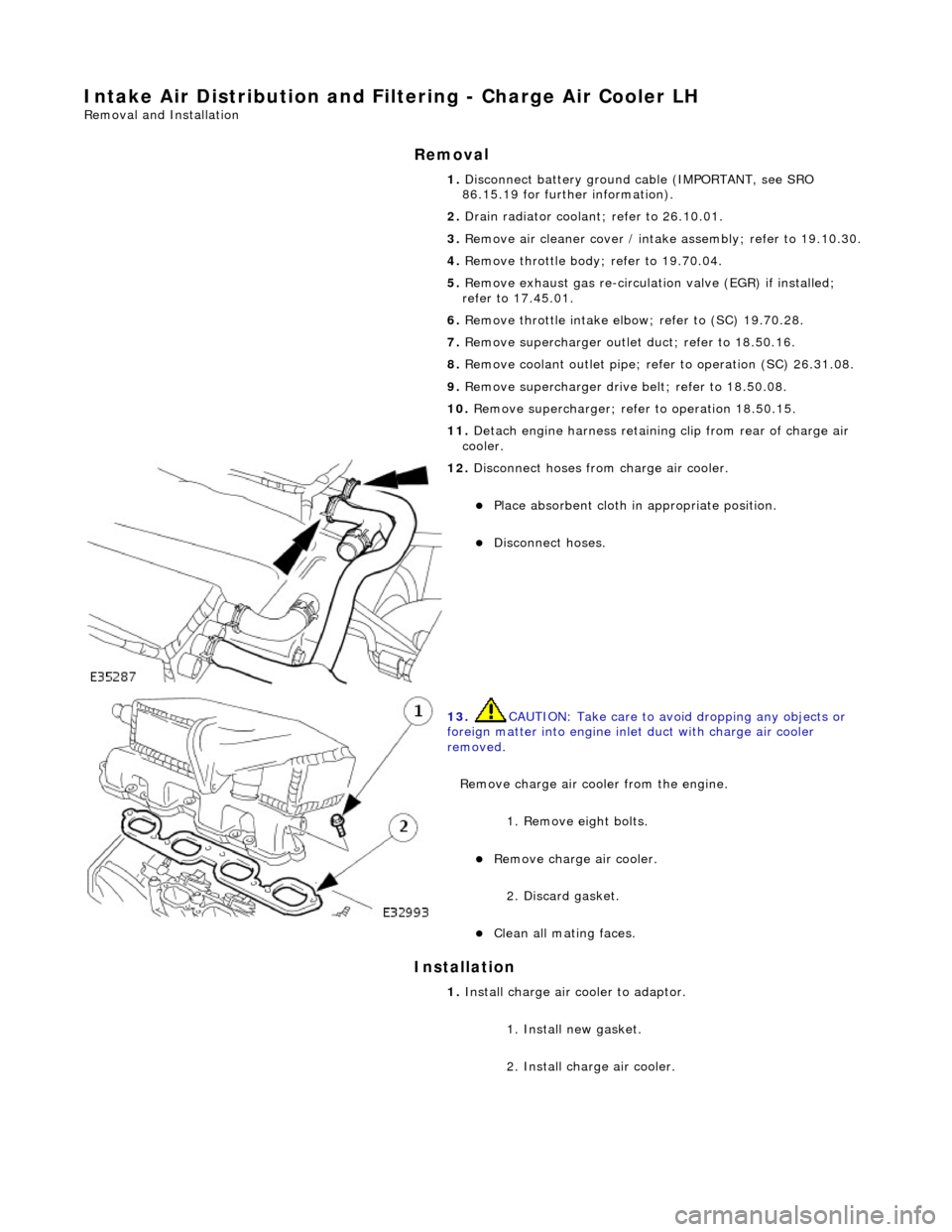
13 .
CAUTI
ON: Take care to avoi
d dropping any objects or
foreign matter into engine inle t duct with charge air cooler
removed.
Remove charge air cooler from the engine.
1. Remove eight bolts.
Remove charge air cooler.
2
. Discard gasket.
Cle
a
n all mating faces.
1.
Install ch
arge air
cooler to adaptor.
1. Install new gasket.
2. Install charge air cooler.
Page 1121 of 2490
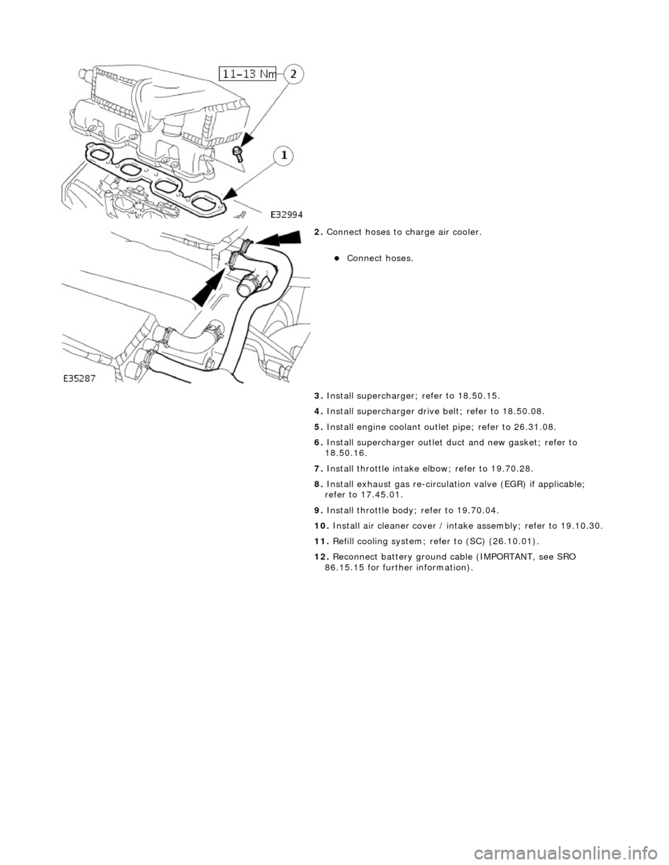
2.
Conne
ct hoses to charge air cooler.
Conne
ct hoses.
3. Install supercharger; refer to 18.50.15.
4. Install supercharger driv e belt; refer to 18.50.08.
5. Install engine coolant outlet pipe; refer to 26.31.08.
6. Install supercharger outlet du ct and new gasket; refer to
18.50.16.
7. Install throttle intake elbow; refer to 19.70.28.
8. Install exhaust gas re-circulation valve (EGR) if applicable;
refer to 17.45.01.
9. Install throttle body ; refer to 19.70.04.
10. Install air cleaner cover / intake assembly; re fer to 19.10.30.
11. Refill cooling system; refer to (SC) (26.10.01).
12. Reconnect battery ground cable (IMPORTANT, see SRO
86.15.15 for further information).
Page 1122 of 2490
Intake Air Distribution and Filtering - Charge Air Cooler RH
Remo
val and Installation
Remov
a
l
Installation
1. Disc onne
ct battery ground cable (IMPORTANT, see SRO
86.15.19 for further information).
2. Drain radiator coolant; refer to 26.10.01.
3. Remove air cleaner cover / intake assembly; refer to 19.10.30.
4. Remove throttle body; refer to 19.70.04.
5. Remove exhaust gas re-circulation valve (EGR) if installed;
refer to 17.45.01.
6. Remove throttle intake elbo w; refer to (SC) 19.70.28.
7. Remove supercharger outlet duct; refer to 18.50.16.
8. Remove coolant outlet pipe; refe r to operation (SC) 26.31.08.
9. Remove supercharger drive belt; refer to 18.50.08.
10. Remove supercharger; refer to operation 18.50.15.
11. Remove intake air temperatur e sensor 2 from charge air
cooler; refer to 18.30.52.
12. Detach engine harness retaining clip from rear of charge air
cooler.
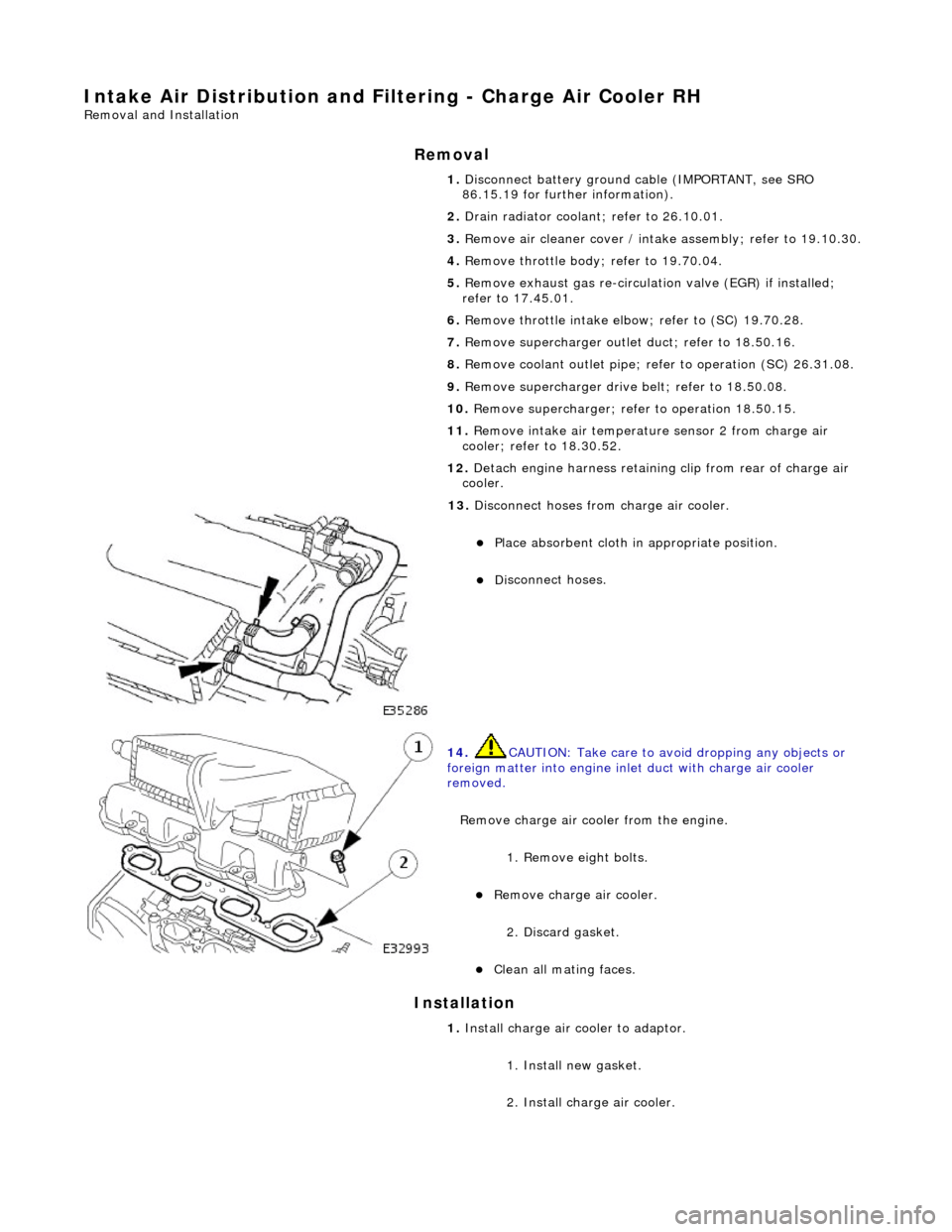
13. Di
sconnect hoses from charge air cooler.
Pla
ce absorbent cloth in appropriate position.
Di
sc
onnect hoses.
14 . CAUTI
ON: Take care to avoi
d dropping any objects or
foreign matter into engine inle t duct with charge air cooler
removed.
Remove charge air cooler from the engine. 1. Remove eight bolts.
Remove charge air cooler.
2
. Discard gasket.
Cle
a
n all mating faces.
1.
Install ch arge air
cooler to adaptor.
1. Install new gasket.
2. Install charge air cooler.