torque JAGUAR X308 1998 2.G Repair Manual
[x] Cancel search | Manufacturer: JAGUAR, Model Year: 1998, Model line: X308, Model: JAGUAR X308 1998 2.GPages: 2490, PDF Size: 69.81 MB
Page 658 of 2490
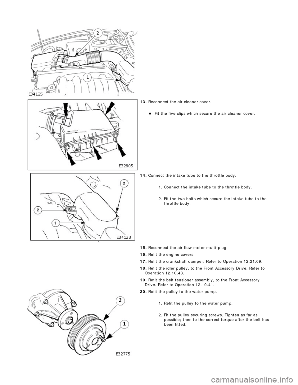
13. Reconnect the air cleaner cover.
пЃ¬Fit the five clips which secu re the air cleaner cover.
14. Connect the intake tube to the throttle body.
1. Connect the intake tube to the throttle body.
2. Fit the two bolts which secure the intake tube to the throttle body.
15. Reconnect the air flow meter multi-plug.
16. Refit the engine covers.
17. Refit the crankshaft damper. Refer to Operation 12.21.09.
18. Refit the idler pulley, to the Front Accessory Drive. Refer to
Operation 12.10.43.
19. Refit the belt tensioner assembly, to the Front Accessory
Drive. Refer to Operation 12.10.41.
20. Refit the pulley to the water pump.
1. Refit the pulley to the water pump.
2. Fit the pulley securing screws. Tighten as far as
possible; then to the correct torque after the belt has
been fitted.
Page 664 of 2490
Engine - Exhaust Camshaft Sprocket LH4.0L NA V8 - AJ27
In-vehicle Repair
Removal
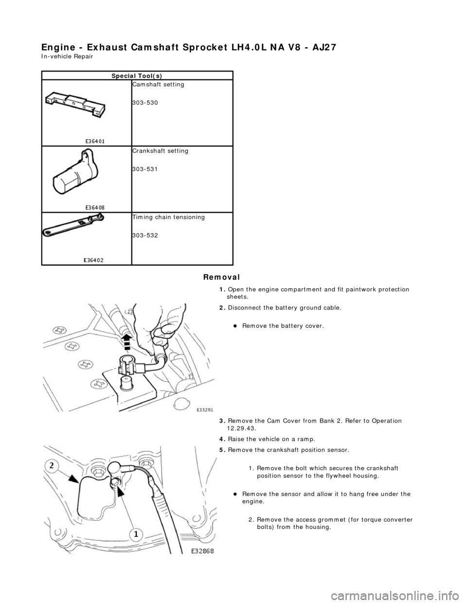
Special Tool(s)
Camshaft setting
303-530
Crankshaft setting
303-531
Timing chain tensioning
303-532
1. Open the engine compartment and fit paintwork protection
sheets.
2. Disconnect the batt ery ground cable.
пЃ¬Remove the battery cover.
3. Remove the Cam Cover from Ba nk 2. Refer to Operation
12.29.43.
4. Raise the vehicle on a ramp.
5. Remove the crankshaft position sensor.
1. Remove the bolt which secures the crankshaft position sensor to the flywheel housing.
пЃ¬Remove the sensor and allow it to hang free under the
engine.
2. Remove the access grommet (for torque converter bolts) from the housing.
Page 668 of 2490
Engine - Exhaust Camshaft Sprocket LH4.0L SC V8 - AJ26/3.2L NA V8 -
AJ26
In-vehicle Repair
Removal
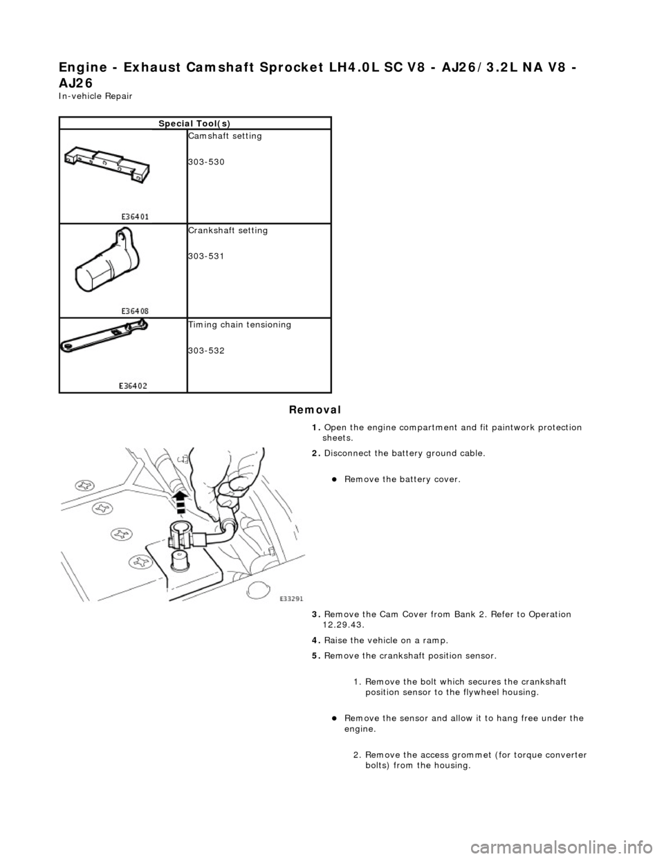
Special Tool(s)
Camshaft setting
303-530
Crankshaft setting
303-531
Timing chain tensioning
303-532
1. Open the engine compartment and fit paintwork protection
sheets.
2. Disconnect the batt ery ground cable.
пЃ¬Remove the battery cover.
3. Remove the Cam Cover from Ba nk 2. Refer to Operation
12.29.43.
4. Raise the vehicle on a ramp.
5. Remove the crankshaft position sensor.
1. Remove the bolt which secures the crankshaft position sensor to the flywheel housing.
пЃ¬Remove the sensor and allow it to hang free under the
engine.
2. Remove the access grommet (for torque converter bolts) from the housing.
Page 672 of 2490
Engine - Exhaust Camshaft Sprocket RH4.0L NA V8 - AJ27
In-vehicle Repair
Removal
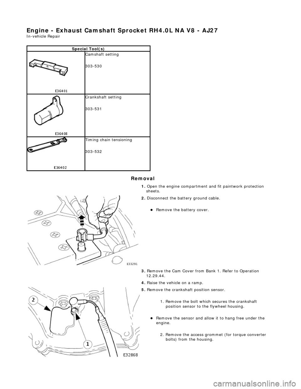
Special Tool(s)
Camshaft setting
303-530
Crankshaft setting
303-531
Timing chain tensioning
303-532
1. Open the engine compartment and fit paintwork protection
sheets.
2. Disconnect the batt ery ground cable.
пЃ¬Remove the battery cover.
3. Remove the Cam Cover from Ba nk 1. Refer to Operation
12.29.44.
4. Raise the vehicle on a ramp.
5. Remove the crankshaft position sensor.
1. Remove the bolt which secures the crankshaft position sensor to the flywheel housing.
пЃ¬Remove the sensor and allow it to hang free under the
engine.
2. Remove the access grommet (for torque converter bolts) from the housing.
Page 677 of 2490
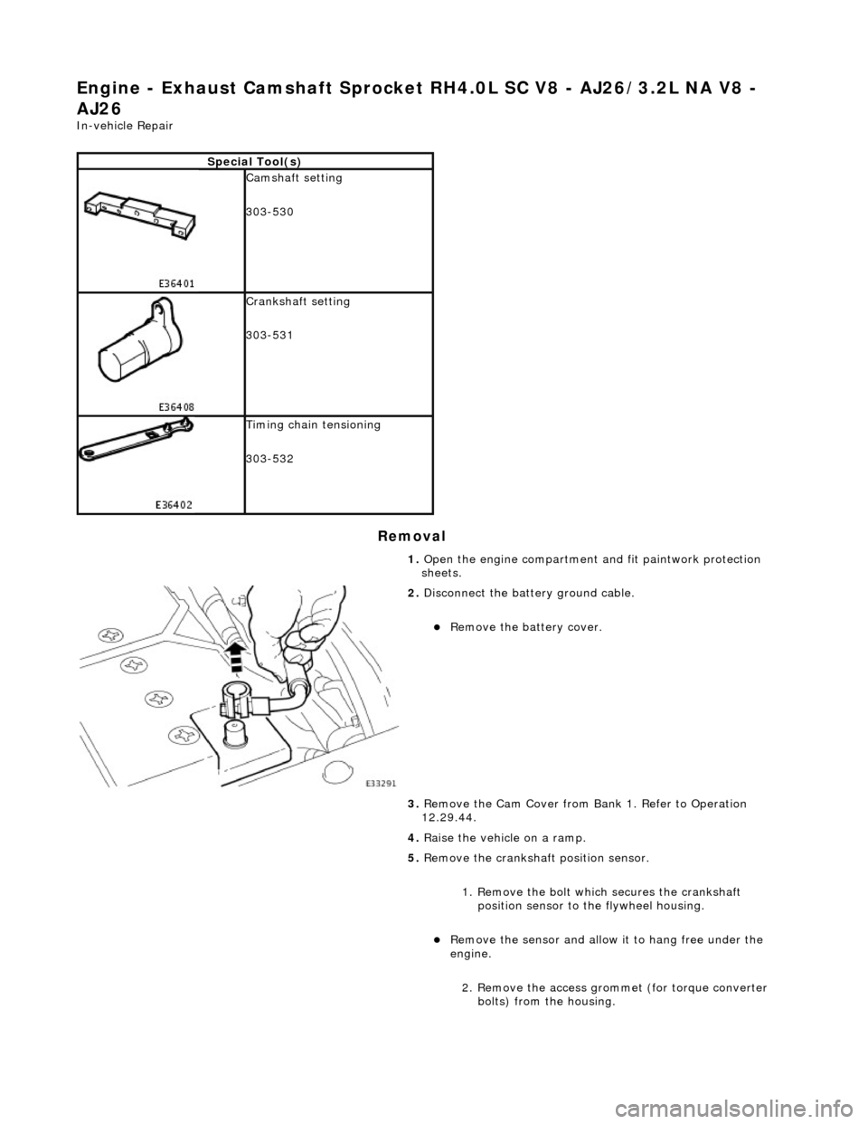
Engine - Exhaust Camshaft Sprocket RH4.0L SC V8 - AJ26/3.2L NA V8 -
AJ26
In-vehicle Repair
Removal
Special Tool(s)
Camshaft setting
303-530
Crankshaft setting
303-531
Timing chain tensioning
303-532
1. Open the engine compartment and fit paintwork protection
sheets.
2. Disconnect the batt ery ground cable.
пЃ¬Remove the battery cover.
3. Remove the Cam Cover from Ba nk 1. Refer to Operation
12.29.44.
4. Raise the vehicle on a ramp.
5. Remove the crankshaft position sensor.
1. Remove the bolt which secures the crankshaft position sensor to the flywheel housing.
пЃ¬Remove the sensor and allow it to hang free under the
engine.
2. Remove the access grommet (for torque converter bolts) from the housing.
Page 751 of 2490
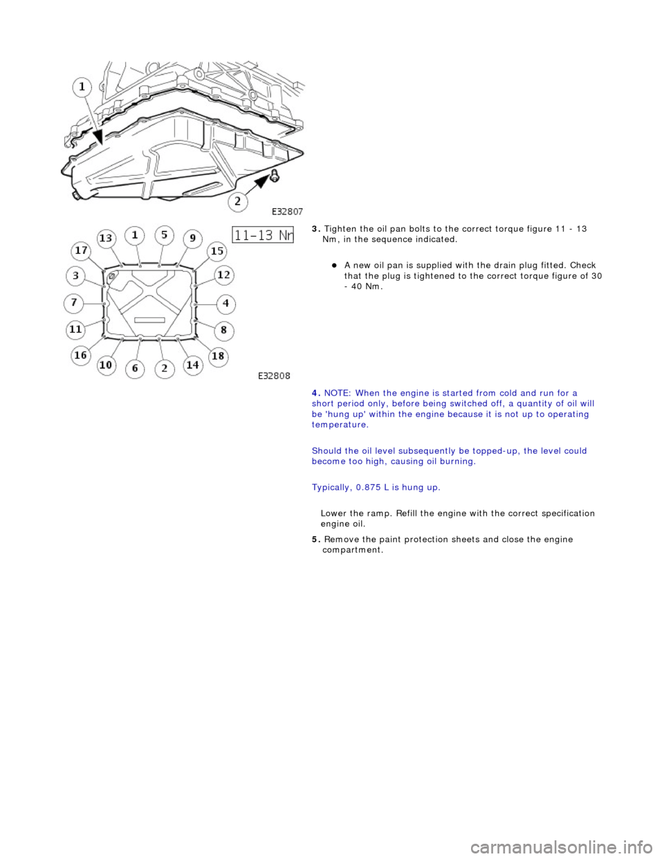
3. Tighten the oil pan bolts to the correct torque figure 11 - 13
Nm, in the sequence indicated.
пЃ¬A new oil pan is supplied with the drain plug fitted. Check
that the plug is tightened to the correct torque figure of 30 - 40 Nm.
4. NOTE: When the engine is star ted from cold and run for a
short period only, before being swit ched off, a quantity of oil will
be 'hung up' within the engine because it is not up to operating
temperature.
Should the oil level subsequently be topped-up, the level could
become too high, causing oil burning.
Typically, 0.875 L is hung up.
Lower the ramp. Refill the engine with the correct specification
engine oil.
5. Remove the paint protection sheets and close the engine
compartment.
Page 753 of 2490
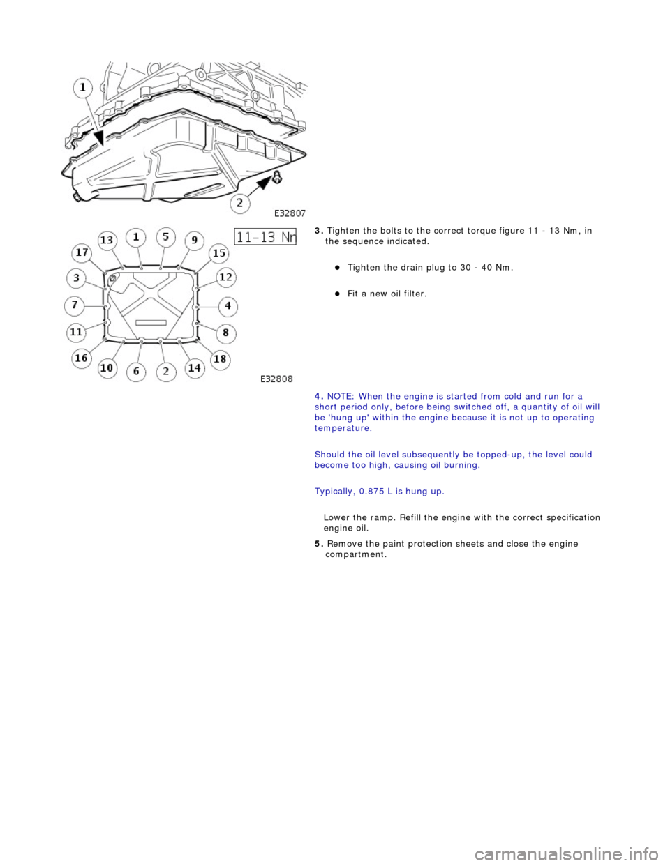
3. Tighten the bolts to the correct torque figure 11 - 13 Nm, in
the sequence indicated.
пЃ¬Tighten the drain plug to 30 - 40 Nm.
пЃ¬Fit a new oil filter.
4. NOTE: When the engine is star ted from cold and run for a
short period only, before being swit ched off, a quantity of oil will
be 'hung up' within the engine because it is not up to operating
temperature.
Should the oil level subsequently be topped-up, the level could
become too high, causing oil burning.
Typically, 0.875 L is hung up.
Lower the ramp. Refill the engine with the correct specification
engine oil.
5. Remove the paint protection sheets and close the engine
compartment.
Page 761 of 2490

2. Remove the access grommet (for torque converter bolts) from the housing.
11. Fit the damper securing bolt (old one) to the crankshaft,
hand-tight only.
12. Rotate the crankshaft until the triangular arrow indent on
the drive plate is visible thro ugh the access hole; confirm
that the timing flat on ea ch camshaft is uppermost.
13. Fit the crankshaft setting peg 303 - 531 to the crankshaft
position sensor location.
1. Fit the crankshaft setting peg 303 - 531.
1. Position the crankshaft so that the setting peg engages fully into the timing slot.
2. Fit and tighten the bolt to secure the setting peg.
14. Remove the damper securing bolt from the crankshaft.
15. Lower the vehicle on the ramp.
16. Fit the camshaft locking tool 303 - 530 to the A-Bank
camshafts, aligning the shafts slightly as necessary.
17. Loosen the bolt which secures the sprocket to the camshaft.
Page 771 of 2490

position sensor to the flywheel housing.
пЃ¬Remove the sensor and allow it to hang free under the
engine.
2. Remove the access grommet (for torque converter bolts) from the housing.
7. Install the damper securing bolt (old one) to the crankshaft,
hand-tight only.
8. Rotate the crankshaft until the triangular arrow indent on
the drive plate is visible thro ugh the access hole; confirm
that the timing flat on ea ch camshaft is uppermost.
9. Install the crankshaft setting peg 303-531 to the crankshaft
position sensor location.
1. Install the crankshaft setting peg 303-531.
пЃ¬Position the crankshaft so that the setting peg engages
fully into the timing slot.
2. Install and tighten the bolt to secure the setting peg.
10. Remove the damper securing bolt from the crankshaft.
11. Lower the vehicle on the ramp.
12. Install the camshaft locking tool 303-530 to Bank 1
camshafts, aligning the shafts slightly as necessary.
13. Loosen the bolt which secures the sprocket to the exhaust
camshaft.
Page 780 of 2490

2. Release the carrier from the two ring dowels and
remove it.
6. Remove the seals from the bush carrier.
1. Remove the sealing ring (scarf jointed) from the
carrier bush groove.
2. Remove the O-ring from the carrier oil-way recess.
7. Raise the vehicle on a ramp.
8. Remove the crankshaft position sensor.
1. Remove the bolt which secures the crankshaft position sensor to the flywheel housing.
пЃ¬Remove the sensor and allow it to hang free under the
engine.
2. Remove the access grommet (for torque converter bolts) from the housing.
9. Fit the damper securing bolt (old one) to the crankshaft, hand-
tight only.
10. Rotate the crankshaft until the triangular arrow indent on
the drive plate is visible thro ugh the access hole; confirm
that the timing flat on ea ch camshaft is uppermost.
11. Fit the crankshaft setting peg 303 - 531 to the crankshaft
position sensor location.