brake sensor JAGUAR X308 1998 2.G Owner's Guide
[x] Cancel search | Manufacturer: JAGUAR, Model Year: 1998, Model line: X308, Model: JAGUAR X308 1998 2.GPages: 2490, PDF Size: 69.81 MB
Page 1390 of 2490
Stator, intermediate and output shafts. Three epicyclic geartrains. Six multi-disc clutch/brake packs. Two freewheels (One-way clutches). Hydraulic pump. Parking lock assembly. Electro-hydraulic control unit. Internal harness and 13 pin connector with bayonet lock.
Hydraulic pump
This engine driven pump is located at the front of the transmission casing and provides pressure for the hydraulic
functions.
Supplies fluid under pressure to the torq ue converter, geartrain, electro-hydraulic control unit and the lubrication
circuit.
Draws fluid from the fluid pa n below the transmission casing, through a filter.
Parking lock
This component prevents movement of th e vehicle by engaging a fixed pawl with the parking lock gear located on the
output shaft. The pawl is engaged by movi ng the gear selector lever to the park (P) position.
Electro-hydraulic control unit
This unit, mounted in the transmission lower case, converts signals, mechanical from the J-gate and electrical from the
TCM, into hydraulic functions.
The following components ar e assembled to the unit:
Selector valve. Shift plate. Control valve - modulating pressure. Control valve - shift pressure. Solenoid valve 1 <-> 2 and 4 <-> 5 shift. Solenoid valve 3 <-> 4 shift. Solenoid valve 2 <-> 3 shift. Solenoid valve - converter lock-up. Speed sensors (2). Temperature sensor.
Speed sensors
There are two speed sensors within the transmission assembly which provide input to the TCM. These inputs, when used in
conjunction with CAN data relative to engine speed (from ECM) and road speed (from ABS), are used to electronically
control the transmission.
Temperature sensor
The output from this sensor allows the TCM to compensate for the affect of fluid temperature on shift time and quality
Control Systems
Hydraulic Control
The selector valve is operated directly by the J-gate and directs fluid flow for P R N D.
Of the four solenoid valves, 3 control shifts and 1 controls converter lock-up. One control valve controls modulating pressure
and the other shift pressure.
Regulating valves are used to maintain/control pressure for lu brication, normal operating functions, and the supply to the
control valves and shift valves.
Page 1989 of 2490
Wiring Harnesses - Wiring Harness
Description and Operation
Introduction
CAUTION: Do not use any other heat shrink sleeve other than the approved glue lined heat shrink sleeve mentioned
in the repair procedure.
The purpose of this document is to promote quick and efficient minor repair to harness connectors or cables using approved
methods and the wiring harness repair kit. Repairs may only be made to cables and connectors which have been
mechanically, not electrically damaged. It also applies wher e the whole extent of the damage can be clearly identified and
rectified.
Care and neatness are essential requir ements in making a perfect repair.
Caution:
At the time of this first issue of the Harness Repair Guide, do not approve re pairs to any of the following circuits:
Any media orientated system transport network harnesses. Supplement restraint system (SRS) firing circuits (Air bags). Link lead assembles, which are unique to safety critical circuits such as anti-lock brake system (ABS) and
thermocouple circuits. An example of this is the ABS wheel speed sensors with moulded connectors.
4. Screened cables, leads and wiring harness(s).
If any harness(s) with defective electrical connector te rminals or wires from the above circuits are a concern,
new components must be installed.
Repair Kit
CAUTION: Where the repair procedure indica tes that a glue lined heat shrink sleeve should be applied, apply sufficient
heat to the glue lined heat shrink to melt the glue in order to provide a water tight seal. Do not over heat the glue lined
heat shrink sleeve so that the wiring harness insulation becomes damaged.
The wiring harness repair kit has been produced which comprises:
Pre-terminated wiring harness(s) of different sizes and types Three sizes of butt splice connectors A selection of colored cable identification sleeves Two sizes of glue lined heat shrink sleeves Crimping pliers A wire cutter and insulation stripper An electrical connector terminal extraction handle and tips
A suitable heat source, fo r shrinking heat shrink sleeves will be required.
The pre-insulated diamond grip range of el ectrical connector terminals and in-line, butt splice connectors contained within
the wiring harness repair kit are the only acceptable product for the repairs of wi ring harnesses. The butt connectors not
only grip the wire but also the insu lation, making a very secure joint.
If an electrical connector terminal is not included in the wiring harness repair kit then approval for the repair is NOT given
and in these circumstances a new wi ring harness must be installed.
Pre-Terminated Wiring Harness( s) and Butt Splice Connectors
All pre-terminated wiring harness(s) and butt splice connectors in the wiring harness repair kit are contained in bags which
can be resealed after use. Each bag is marked with the part number of the items stored within the bag. Each storage
compartment in the wiring harness repair kit is identified with the corresponding part number. Make sure that pre-
terminated wiring harness(s) and connectors are not mixed up it is advisable to only open one bag at a time and to reseal
Page 2423 of 2490
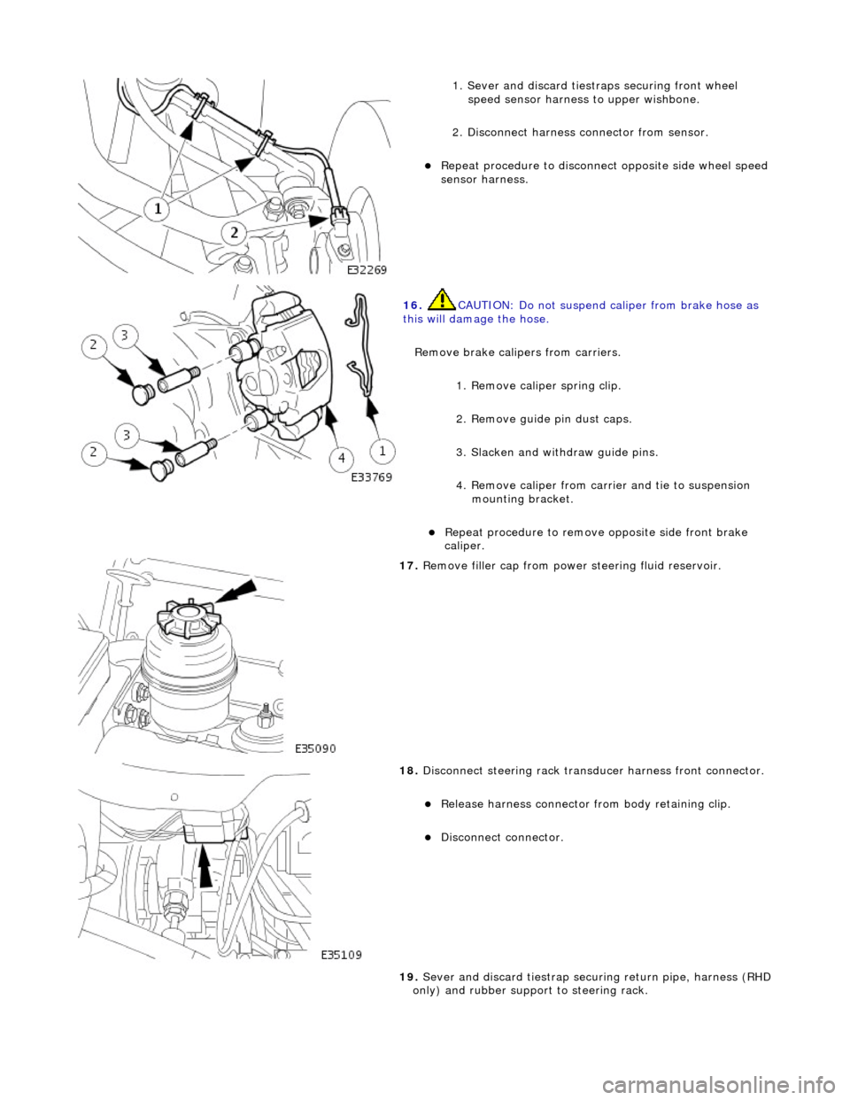
1. Sever and discard tiestraps securing front wheel
speed sensor harness to upper wishbone.
2. Disconnect harness connector from sensor.
Repeat procedure to disconnect opposite side wheel speed
sensor harness.
16. CAUTION: Do not suspend caliper from brake hose as
this will damage the hose.
Remove brake calipers from carriers.
1. Remove caliper spring clip.
2. Remove guide pin dust caps.
3. Slacken and withdraw guide pins.
4. Remove caliper from carrier and tie to suspension mounting bracket.
Repeat procedure to remove opposite side front brake
caliper.
17. Remove filler cap from power steering fluid reservoir.
18. Disconnect steering rack transducer harness front connector.
Release harness connector from body retaining clip.
Disconnect connector.
19. Sever and discard tiestrap secu ring return pipe, harness (RHD
only) and rubber support to steering rack.
Page 2436 of 2490
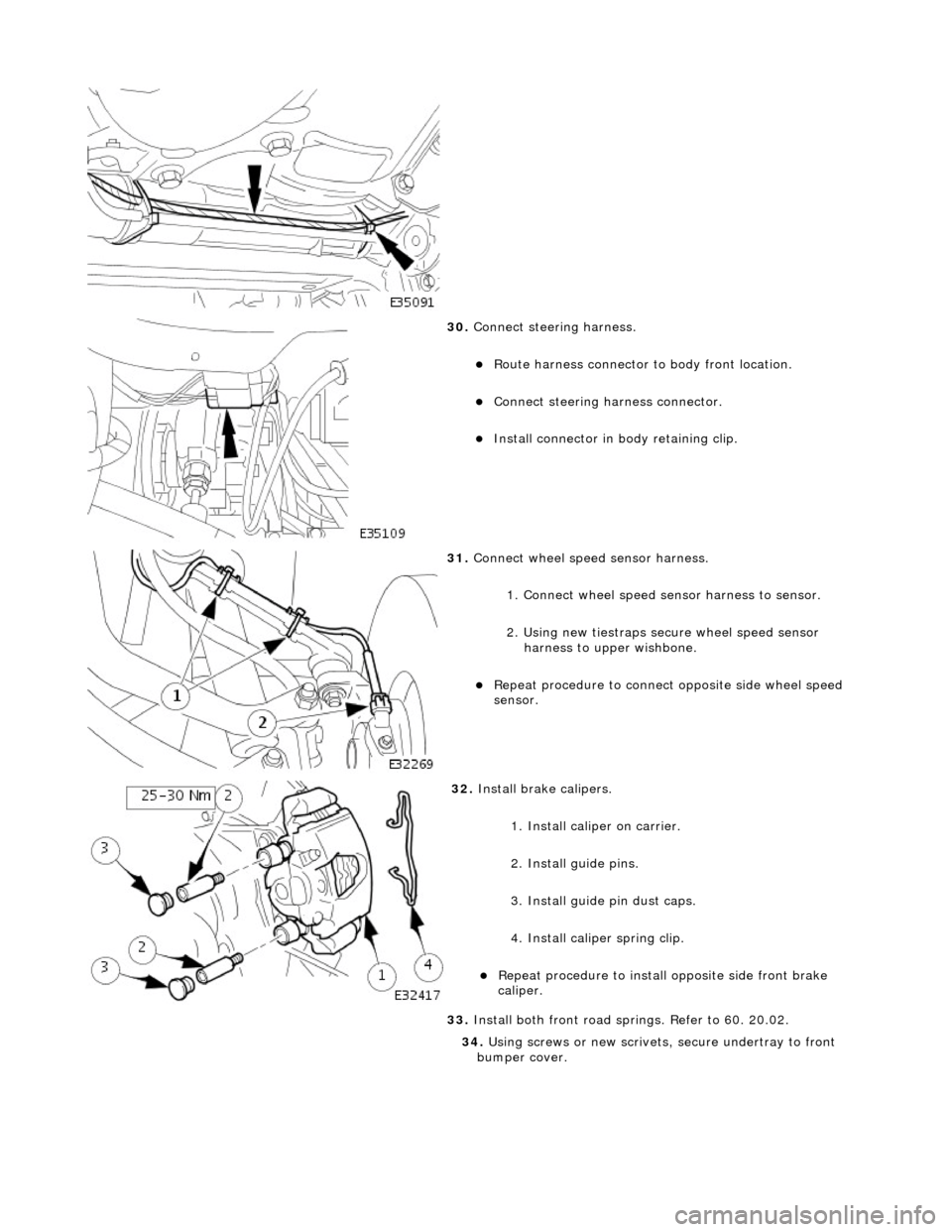
30. Connect steering harness.
Route harness connector to body front location.
Connect steering ha rness connector.
Install connector in body retaining clip.
31. Connect wheel speed sensor harness.
1. Connect wheel speed sensor harness to sensor.
2. Using new tiestraps secure wheel speed sensor harness to upper wishbone.
Repeat procedure to connect opposite side wheel speed
sensor.
32. Install brake calipers.
1. Install caliper on carrier.
2. Install guide pins.
3. Install guide pin dust caps.
4. Install caliper spring clip.
Repeat procedure to install opposite side front brake
caliper.
33. Install both front road sp rings. Refer to 60. 20.02.
34. Using screws or new scrivets , secure undertray to front
bumper cover.
Page 2463 of 2490
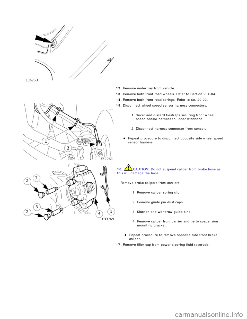
12. Remove undertray from vehicle.
13. Remove both front road wheels. Refer to Section 204-04.
14. Remove both front road springs. Refer to 60. 20.02.
15. Disconnect wheel speed sensor harness connectors.
1. Sever and discard tiestr aps securing front wheel
speed sensor harness to upper wishbone.
2. Disconnect harness connector from sensor.
Repeat procedure to disconnect opposite side wheel speed
sensor harness.
16. CAUTION: Do not suspend caliper from brake hose as
this will damage the hose.
Remove brake calipers from carriers.
1. Remove caliper spring clip.
2. Remove guide pin dust caps.
3. Slacken and withdraw guide pins.
4. Remove caliper from carrier and tie to suspension mounting bracket.
Repeat procedure to remove opposite side front brake
caliper.
17. Remove filler cap from power steering fluid reservoir.
Page 2478 of 2490
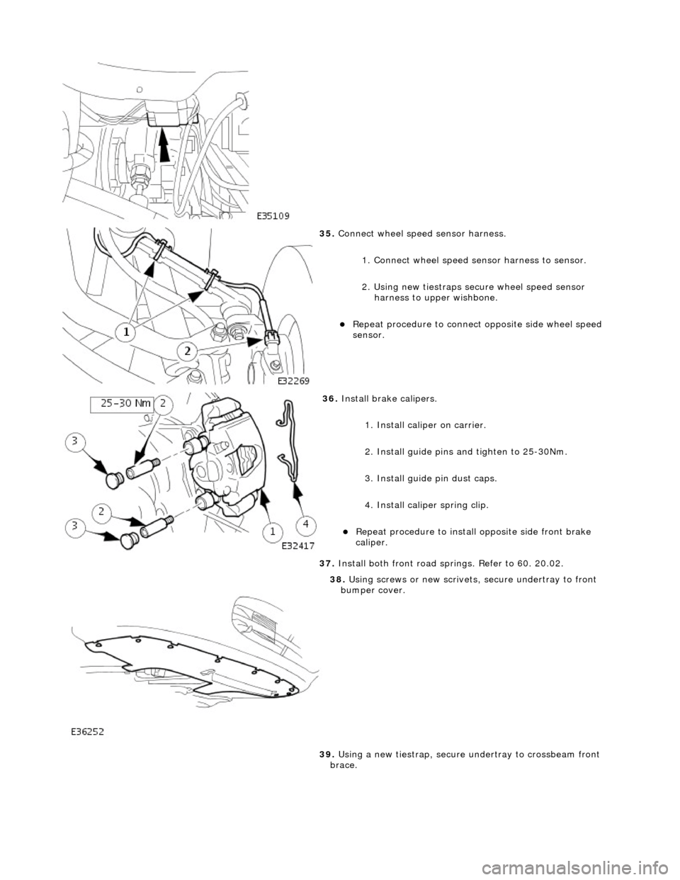
35. Connect wheel speed sensor harness.
1. Connect wheel speed sensor harness to sensor.
2. Using new tiestraps secure wheel speed sensor harness to upper wishbone.
Repeat procedure to connect opposite side wheel speed
sensor.
36. Install brake calipers.
1. Install caliper on carrier.
2. Install guide pins and tighten to 25-30Nm.
3. Install guide pin dust caps.
4. Install caliper spring clip.
Repeat procedure to install opposite side front brake
caliper.
37. Install both front road sp rings. Refer to 60. 20.02.
38. Using screws or new scrivets , secure undertray to front
bumper cover.
39. Using a new tiestrap, secure undertray to crossbeam front
brace.