headlamp JAGUAR X308 1998 2.G Owner's Guide
[x] Cancel search | Manufacturer: JAGUAR, Model Year: 1998, Model line: X308, Model: JAGUAR X308 1998 2.GPages: 2490, PDF Size: 69.81 MB
Page 2344 of 2490
Bumpers - Front Bumper
Removal and Installation
Removal
WARNING: ENSURE THAT ALL PERSONNEL AND EQUIPMENT ARE CLEAR OF AREA BEFORE OPERATING RAMP.
1. Position vehicle on 4-post ramp.
2. Remove battery cover and disc onnect ground cable from
battery terminal. Refer to 86.15.19
3. Remove radiator surround and grill. Refer to 76.55.15 and
76.55.03.
4. Raise ramp to working height.
5. Using wheel-free lifts, remove front wheels.
6. Remove wheelarch liners for access.
7. Remove undertray. Refer to 76.22.90.
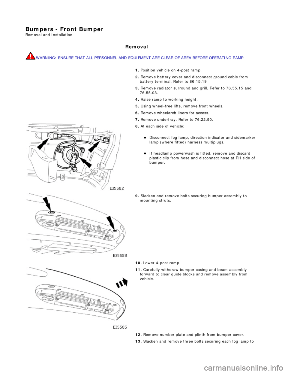
8. At each side of vehicle:
Disconnect fog lamp, directio n indicator and sidemarker
lamp (where fitted) harness multiplugs.
If headlamp powerwash is fitted, remove and discard
plastic clip from hose and disconnect hose at RH side of
bumper.
9. Slacken and remove bolts securing bumper assembly to
mounting struts.
10. Lower 4-post ramp.
11. Carefully withdraw bumper casing and beam assembly
forward to clear guide blocks and remove assembly from
vehicle.
12. Remove number plate and plinth from bumper cover.
13. Slacken and remove three bolts securing each fog lamp to
Page 2347 of 2490
Bumpers - Front Bumper and Bumper Cover
Removal and Installation
Removal
WARNING: ENSURE THAT ALL PERSONNEL AND EQUIPMENT ARE CLEAR OF AREA BEFORE OPERATING RAMP.
Installation
1. Position vehicle on 4-post ramp.
2. Remove battery cover and disc onnect ground cable from
battery terminal. Refer to 86.15.19.
3. Remove radiator surround and grill. Refer to 76.55.15 and
76.55.03.
4. Raise ramp to working height.
5. Using wheel-free lifts, remove front wheels.
6. Remove wheelarch liners for access.
7. Remove undertray. Refer to 76.22.90.
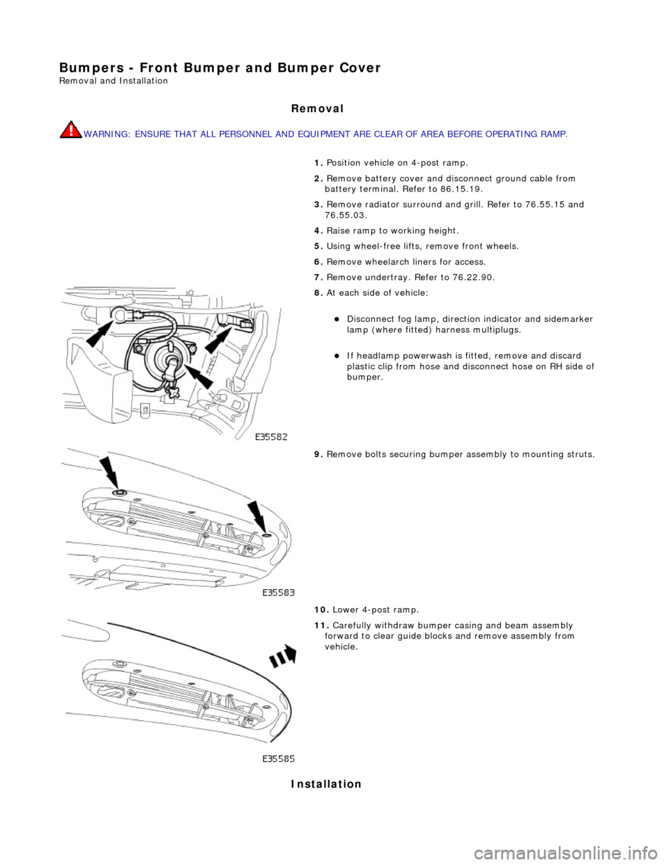
8. At each side of vehicle:
Disconnect fog lamp, directio n indicator and sidemarker
lamp (where fitted) harness multiplugs.
If headlamp powerwash is fitted, remove and discard
plastic clip from hose and disconnect hose on RH side of
bumper.
9. Remove bolts securing bumper assembly to mounting struts.
10. Lower 4-post ramp.
11. Carefully withdraw bumper casing and beam assembly
forward to clear guide blocks and remove assembly from
vehicle.
Page 2348 of 2490

1.
WARNING: ENSURE THAT ALL PERSONNEL AND
EQUIPMENT ARE CLEAR OF AREA BEFORE OPERATING RAMP.
Carefully slide bumper assembly onto fender guide blocks.
2. Raise ramp to working height.
3. Install but do not fully tighten bo lts securing bumper to struts.
4. Check clearance between top of bumper and bottom of fender.
If necessary, remove bumper, adjust guide blocks to achieve
correct clearance and refit bumper.
5. Connect harness multiplugs to foglamps, direction indicators
and where fitted side marker lamps.
6. Install harnesses in retaining clips at each side of cover.
7. Install powerwash hoses to jet assemblies and secure with new
plastic clips. Refer to Section 501.16.
8. Install radiator grill and su rround. refer to 76.55.03 and
76.55.15.
9. Check and as necessary adjust bumper cover to fender,
headlamps and radiator grill surround clearances. Refer to
Description and Operation in this section.
10. Fully tighten bumper assembly to strut securing bolts.
11. Install wheelarch liners.
12. Install undertray. Refer to 76.22.90.
13. Lower 4-post ramp.
14. Install road wheels and lower wheel-free lifts.
Page 2349 of 2490
Bumpers - Front Bumper Cover
Removal and Installation
Removal
WARNING: ENSURE THAT ALL PERSONNEL AND EQUIPMENT ARE CLEAR OF AREA BEFORE OPERATING RAMP.
1. Position vehicle on 4-post ramp.
2. Remove battery cover and disc onnect ground cable from
battery terminal. Refer to 86.15.19.
3. Remove radiator surround and grill. Refer to 76.55.15 and
76.55.03.
4. Raise ramp to working height.
5. Using wheel-free lifts, remove front wheels.
6. Remove wheelarch liners for access.
7. Remove undertray. Refer to 76.22.90.
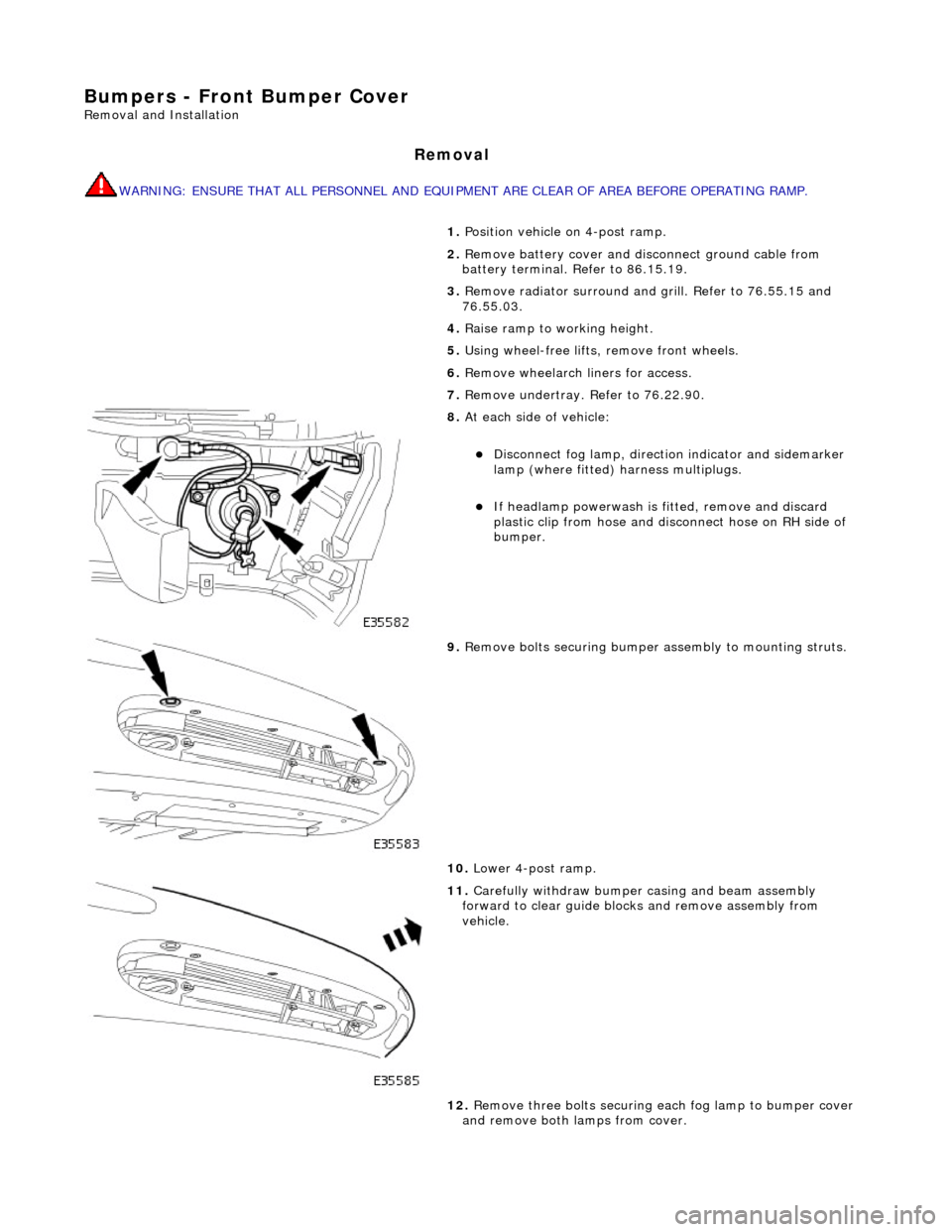
8. At each side of vehicle:
Disconnect fog lamp, directio n indicator and sidemarker
lamp (where fitted) harness multiplugs.
If headlamp powerwash is fitted, remove and discard
plastic clip from hose and disconnect hose on RH side of
bumper.
9. Remove bolts securing bumper assembly to mounting struts.
10. Lower 4-post ramp.
11. Carefully withdraw bumper casing and beam assembly
forward to clear guide blocks and remove assembly from
vehicle.
12. Remove three bolts securing each fog lamp to bumper cover
and remove both lamps from cover.
Page 2351 of 2490
Installation
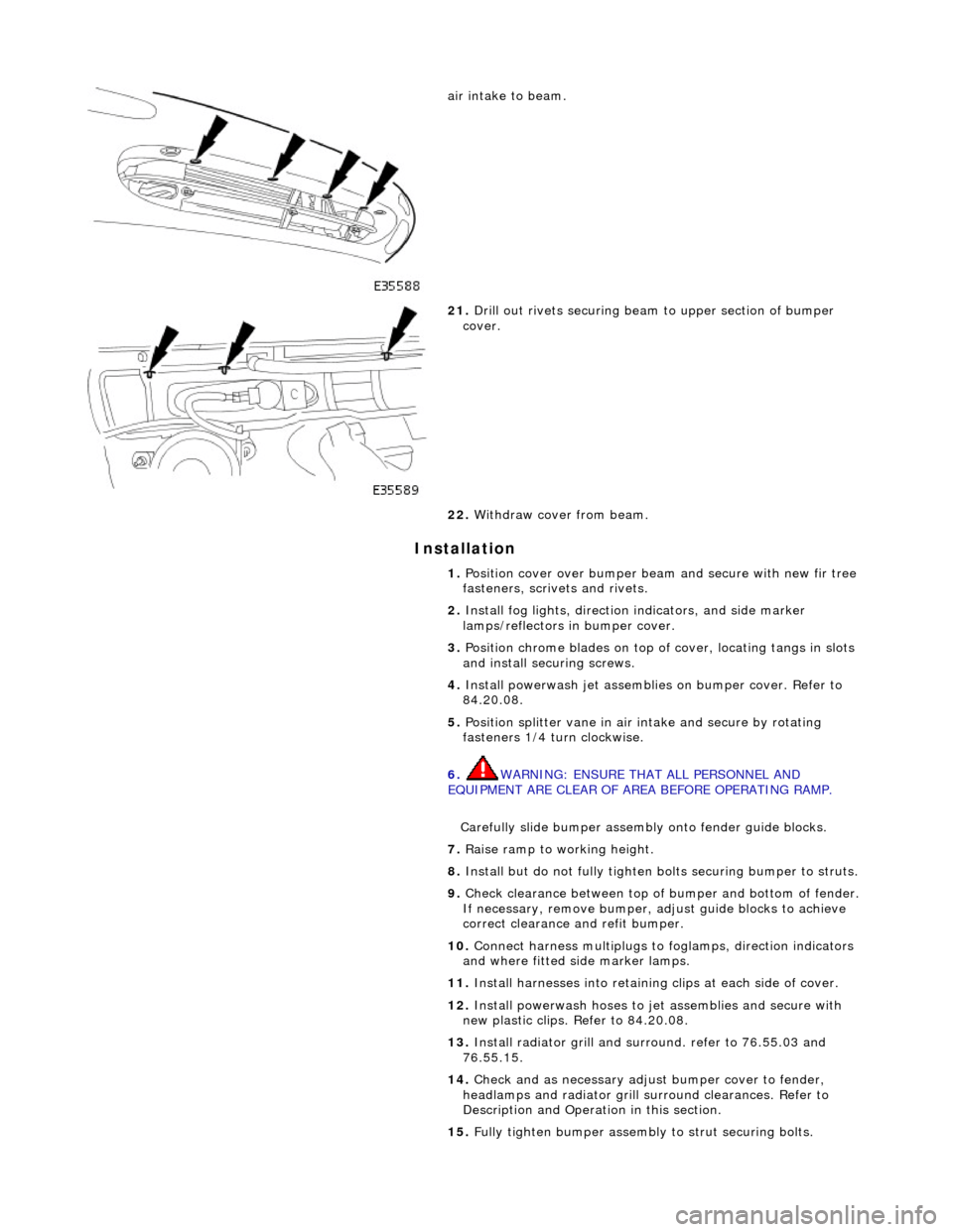
air intake to beam.
21. Drill out rivets securing beam to upper section of bumper
cover.
22. Withdraw cover from beam.
1. Position cover over bumper beam and secure with new fir tree
fasteners, scrivets and rivets.
2. Install fog lights, direction indicators, and side marker
lamps/reflectors in bumper cover.
3. Position chrome blades on top of cover, locating tangs in slots
and install securing screws.
4. Install powerwash jet assemblies on bumper cover. Refer to
84.20.08.
5. Position splitter vane in air intake and secure by rotating
fasteners 1/4 turn clockwise.
6. WARNING: ENSURE THAT ALL PERSONNEL AND
EQUIPMENT ARE CLEAR OF AREA BEFORE OPERATING RAMP.
Carefully slide bumper assembly onto fender guide blocks.
7. Raise ramp to working height.
8. Install but do not fully tighten bo lts securing bumper to struts.
9. Check clearance between top of bumper and bottom of fender.
If necessary, remove bumper, adjust guide blocks to achieve
correct clearance and refit bumper.
10. Connect harness multiplugs to foglamps, direction indicators
and where fitted side marker lamps.
11. Install harnesses into retaining clips at each side of cover.
12. Install powerwash hoses to jet assemblies and secure with
new plastic clips. Refer to 84.20.08.
13. Install radiator grill and su rround. refer to 76.55.03 and
76.55.15.
14. Check and as necessary adjust bumper cover to fender,
headlamps and radiator grill surround clearances. Refer to
Description and Operation in this section.
15. Fully tighten bumper assembly to strut securing bolts.
Page 2408 of 2490
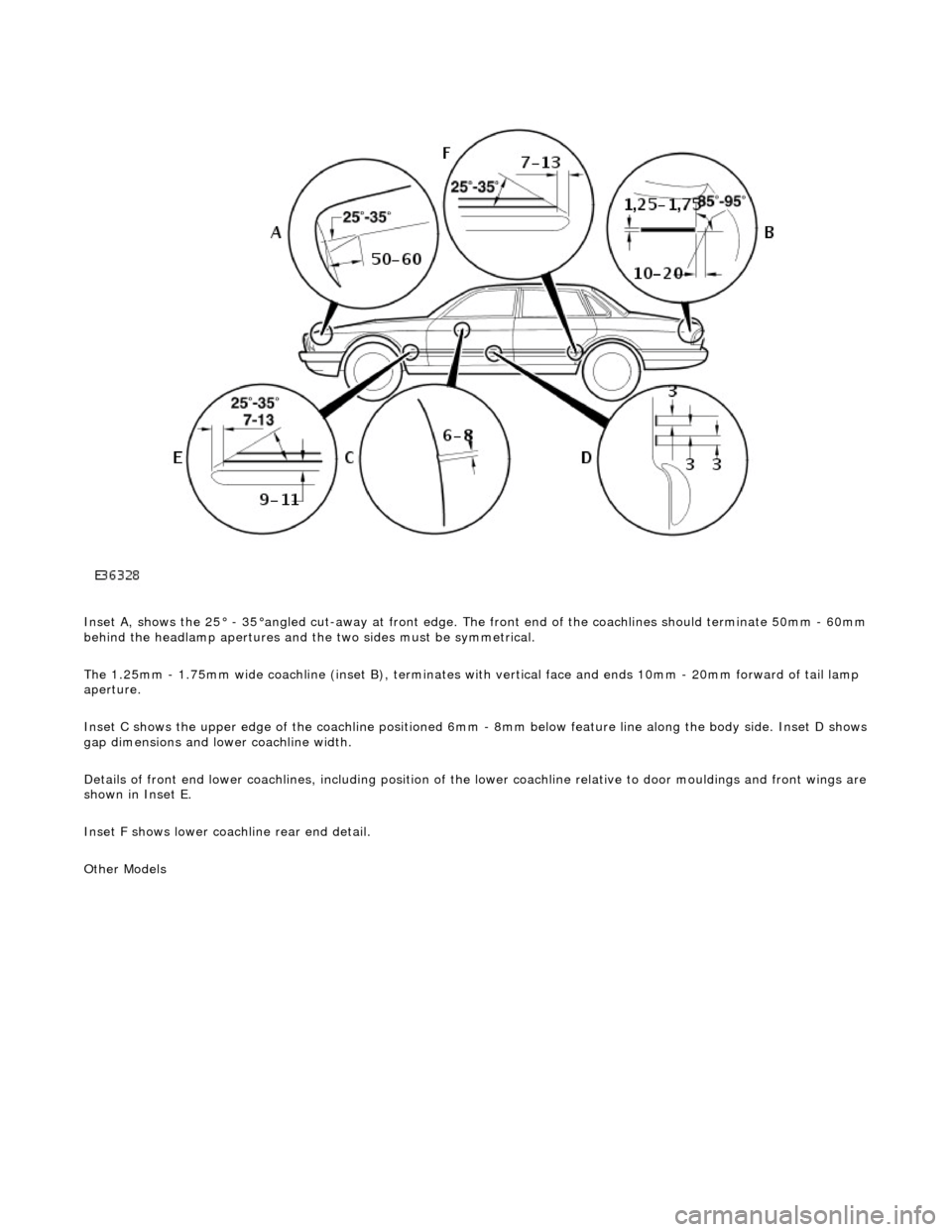
Inset A, shows the 25° - 35°angled cut-away at front edge. The front end of the coachlines should terminate 50mm - 60mm behind the headlamp apertures and the two sides must be symmetrical.
The 1.25mm - 1.75mm wide coachline (inset B), terminates with vertical face and ends 10mm - 20mm forward of tail lamp
aperture.
Inset C shows the upper edge of the coac hline positioned 6mm - 8mm below feature line along the body side. Inset D shows
gap dimensions and lower coachline width.
Details of front end lower coachlines, including position of the lower coachline relative to door mouldings and front wings are
shown in Inset E.
Inset F shows lower coachline rear end detail.
Other Models
Page 2409 of 2490
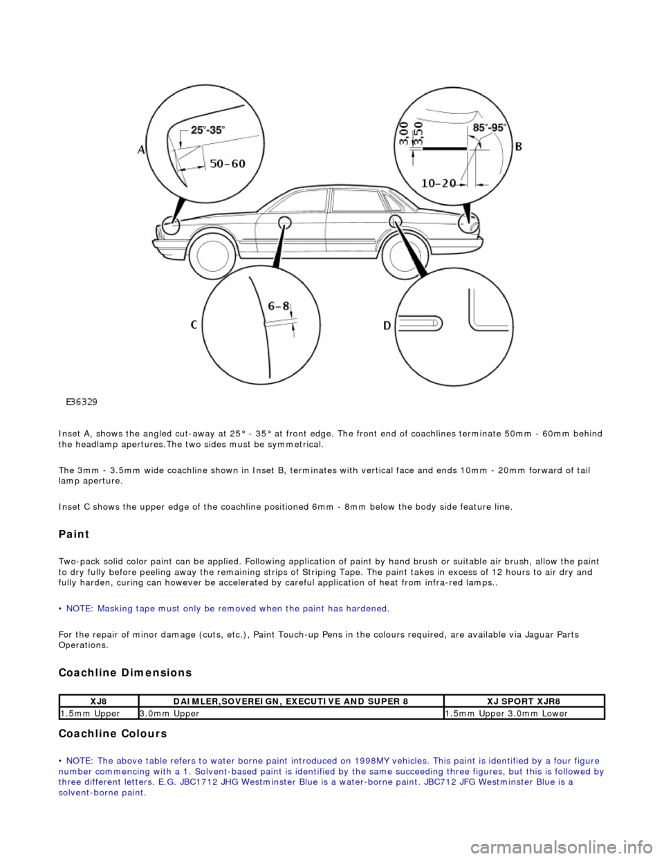
Inset A, shows the angled cut-away at 25° - 35° at front edge. The front end of coachlines terminate 50mm - 60mm behind
the headlamp apertures.The two sides must be symmetrical.
The 3mm - 3.5mm wide coachline shown in Inset B, terminates with vertical face and ends 10mm - 20mm forward of tail
lamp aperture.
Inset C shows the upper edge of th e coachline positioned 6mm - 8mm be low the body side feature line.
Paint
Two-pack solid color paint can be applied. Following application of paint by hand brus h or suitable air brush, allow the paint
to dry fully before peeling away the remain ing strips of Striping Tape. The paint takes in excess of 12 hours to air dry and
fully harden, curing can however be accelerated by careful application of heat from infra-red lamps..
• NOTE: Masking tape must only be removed when the paint has hardened.
For the repair of minor damage (cuts, et c.), Paint Touch-up Pens in the colours required, are available via Jaguar Parts
Operations.
Coachline Dimensions
Coachline Colours
• NOTE: The above table refers to water borne paint introduced on 1998MY vehicles. This paint is identified by a four figure
number commencing with a 1. Solvent-based paint is identified by the same succeeding three figures, but this is followed by three different letters. E.G. JBC1712 JHG Westminster Blue is a water-borne paint. JBC712 JFG Westminster Blue is a
solvent-borne paint.
XJ8DAIMLER,SOVEREIGN, EXECUTIVE AND SUPER 8XJ SPORT XJR8
1.5mm Upper3.0mm Upper1.5mm Upper 3.0mm Lower
Page 2417 of 2490
Panels centered between two adjacent panels must have equal gaps on either side. For exceptions to this, refer to the
appropriate specification. Gaps between ad jacent panels or components must not expose harnesses, labels, brackets or
visually poor joint or assembly conditions.
• NOTE: Sliding roof panel clearances are specified without the edge seal installed.
Areas of particular concern are, fuel filler flap, trunk lid to fenders and saddle panels, hood to fenders, grill and headlamps,
sliding roof to main roof panel, door gaps at fenders, B\C posts, roof drip rail an d rocker panel, and bumper cover to fenders
and cross car assemblies
Alignment
Panels must be correctly profiled to maintain cosmetic appearance, and ensure co rrect seating of seals with minimal wind
noise. Areas of particular concern are hood to fenders, trunk lid to fenders and saddle panels, doors to apertures, doors to
fenders and adjacent doors and relationship of the sliding roof panel leading and trailing edges to the main roof panel.
Exterior Fitments
Bezels, trims and lamps must be concentric with apertu res and have equal clearances with adjacent panels.
Areas of particular concern are headlamp to hood, fender and trim panel, exhaust tailpipe trim to bumper cover cut-out,
rear lamp assembly to trunk lid, fender and bumper cover trim, and side feature lines including body side mouldings, fender
to door and door to door.
Exterior Clearances and Alignments-Front