ECU JAGUAR X308 1998 2.G Workshop Manual
[x] Cancel search | Manufacturer: JAGUAR, Model Year: 1998, Model line: X308, Model: JAGUAR X308 1998 2.GPages: 2490, PDF Size: 69.81 MB
Page 889 of 2490
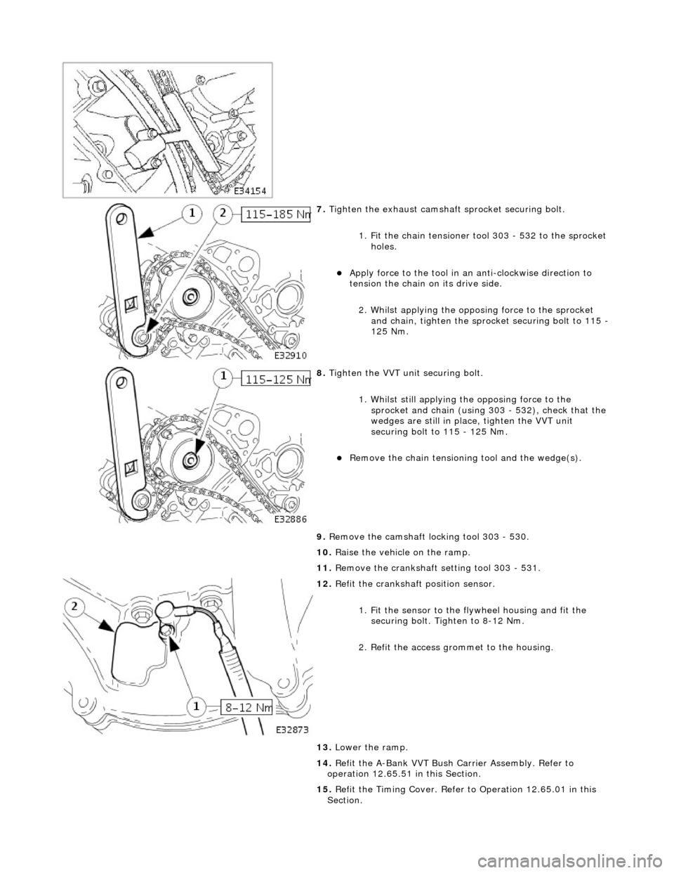
7. Tighten the exhaust camshaft sprocket securing bolt.
1. Fit the chain tensioner tool 303 - 532 to the sprocket holes.
Apply force to the tool in an anti-clockwise direction to
tension the chain on its drive side.
2. Whilst applying the opposing force to the sprocket and chain, tighten the sprock et securing bolt to 115 -
125 Nm.
8. Tighten the VVT unit securing bolt.
1. Whilst still applying the opposing force to the
sprocket and chain (using 303 - 532), check that the
wedges are still in place, tighten the VVT unit
securing bolt to 115 - 125 Nm.
Remove the chain tensioning tool and the wedge(s).
9. Remove the camshaft locking tool 303 - 530.
10. Raise the vehicle on the ramp.
11. Remove the crankshaft setting tool 303 - 531.
12. Refit the crankshaft position sensor.
1. Fit the sensor to the fl ywheel housing and fit the
securing bolt. Tighten to 8-12 Nm.
2. Refit the access grommet to the housing.
13. Lower the ramp.
14. Refit the A-Bank VVT Bush Carrier Assembly. Refer to
operation 12.65.51 in this Section.
15. Refit the Timing Cover. Refer to Operation 12.65.01 in this
Section.
Page 891 of 2490

Engine - Variable Camshaft Timing Oil Control Unit Housing LH
In-vehicle Repair
Removal
Installation
1. Open the engine compartment and fit paintwork protection
sheets.
2. Set the engine compartment cover to the service access
position.
3. Disconnect the batt ery ground cable.
Remove the battery cover.
4. Remove the Timing Co ver. Refer to Operation 12.65.01 in this
Section.
5. Remove the VVT bush carrier.
1. Remove the two bolts and one nut which secure the carrier to the cylinder block.
2. Release the carrier from the two ring dowels and
remove it.
6. Remove the seals from the bush carrier.
1. Remove the sealing ring (scarf jointed) from the
carrier bush groove.
2. Remove the O-ring from the carrier oil-way recess.
7. Clean and inspect all relevant components.
1. Fit new seals to the bush carrier.
1. Fit the new sealing ring (scarf jointed) to the carrier bush groove.
2. Fit a new O-ring to the carrier oil-way.
Page 892 of 2490

2. Fit the bush carrier to the cylinder block.
Lubricate the seal (scarf jointed) and the bush.
1. Fit the bush carrier assembly.
Check that the seals are in pl ace and that the ring dowels
are engaged squarely. Fully locate the assembly as much
as possible by hand pressure.
2. Fit the two securing bolts and one nut. Tighten to 19- 23 Nm.
3. Refit the Timing Cover. Refer to Operation 12.65.01 in this
Section.
4. Move the engine compartment co ver from the service position
and connect the gas struts.
5. Remove the paint protection sheets and close the cover.
6. Connect the battery and fit the battery cover.
Refer to the Battery Reconnection Procedure 86.15.15.
Page 893 of 2490

V
ariable Camshaft Timing Oil Control Unit Housing RH
12.65.51
Removal
1. Open the engine compartment and fit paintwork protection sheets.
2. Set the engine compartment cover to the service access position.
3
. Disconnect the battery ground cable.
Remove the battery cover.
4. Remove the Timing Cover. Refer to Operation <<12.65.01>>
in this Section.
5
. Remove the VVT bush carrier.
1. Remove the three bolts which secure the carrier to the cylinder block.
Page 895 of 2490

2
. Fit the bush carrier to the cylinder block.
Lubricate the seal (scarf jointed) and the bush.
1. Fit the bush carrier assembly.
Check that the seals are in place and that the ring dowels are engaged squarely. Fully locate the
assembly as much as possible by hand pressure. 2. Fit the three securing bolts. Tighten to 19-23 Nm.
3. Refit the Timing Cover. Refer to Operation <<12.65.01>> in this Section.
4. Move the engine compartment cover from the service position and connect the gas struts.
5. Remove the paint protection sheets and close the cover.
6. Connect the battery and fit the battery cover. Refer to the Battery Reconnection Procedure <<86.15.15>>.
Page 898 of 2490
ENSURE THAT ALL FIRE PREVENTION PROCEDURES ARE ACTIVE.
BEFORE PROCEEDING, IT IS ESSENTIAL THAT THE WARNING NOTES GIVEN IN SECTION 100-00 (UNDER THE
HEADING 'SAFETY PRECAUTIONS') ARE READ AND UNDERSTOOD.
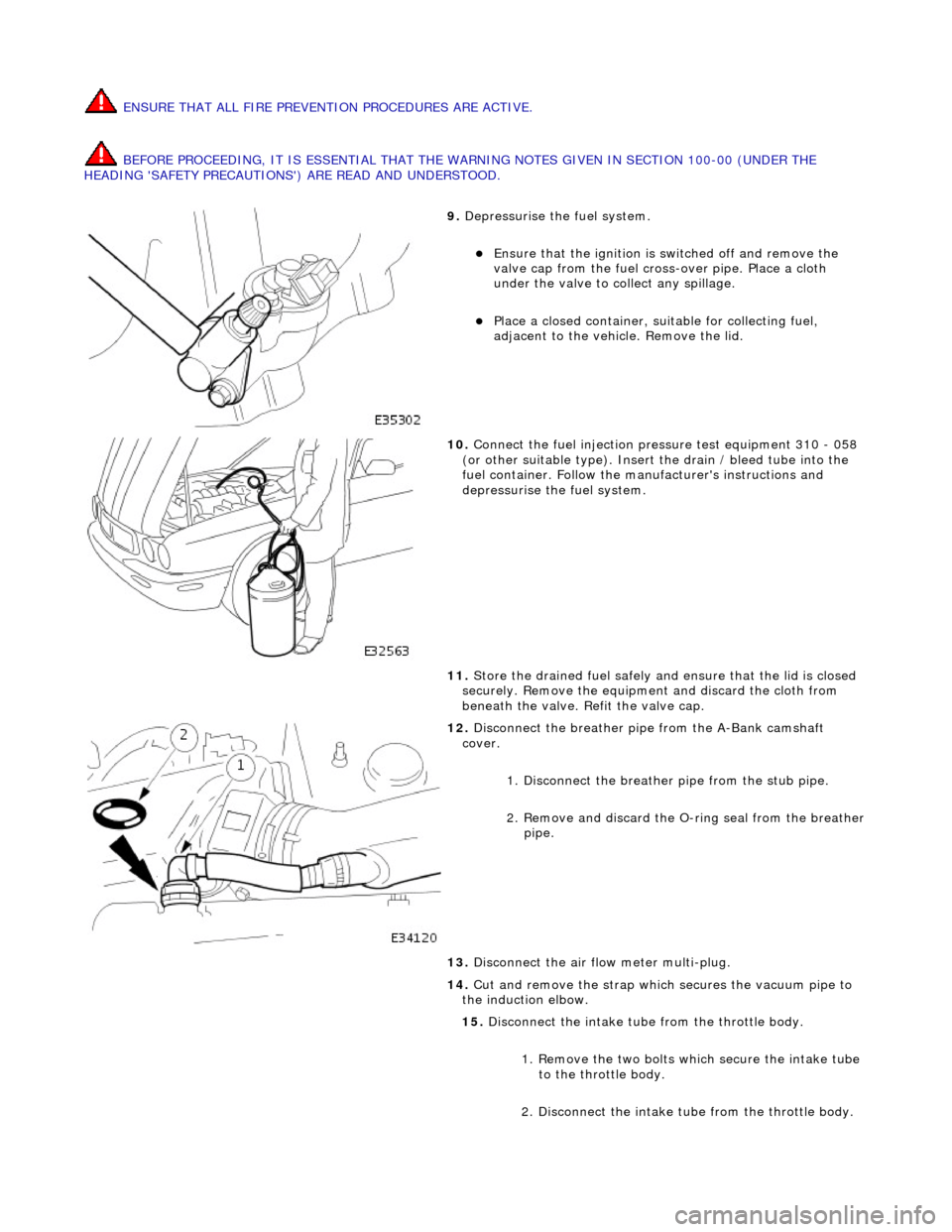
9. Depressurise the fuel system.
Ensure that the ignition is switched off and remove the
valve cap from the fuel cross-over pipe. Place a cloth
under the valve to collect any spillage.
Place a closed container, su itable for collecting fuel,
adjacent to the vehicle. Remove the lid.
10. Connect the fuel injection pressure test equipment 310 - 058
(or other suitable type). Insert the drain / bleed tube into the
fuel container. Follow the ma nufacturer's instructions and
depressurise the fuel system.
11. Store the drained fuel safely and ensure that the lid is closed
securely. Remove the equipmen t and discard the cloth from
beneath the valve. Refit the valve cap.
12. Disconnect the breather pipe from the A-Bank camshaft
cover.
1. Disconnect the breather pipe from the stub pipe.
2. Remove and discard the O-ring seal from the breather
pipe.
13. Disconnect the air flow meter multi-plug.
14. Cut and remove the strap which secures the vacuum pipe to
the induction elbow.
15. Disconnect the intake tube from the throttle body.
1. Remove the two bolts which secure the intake tube to the throttle body.
2. Disconnect the intake tube from the throttle body.
Page 900 of 2490
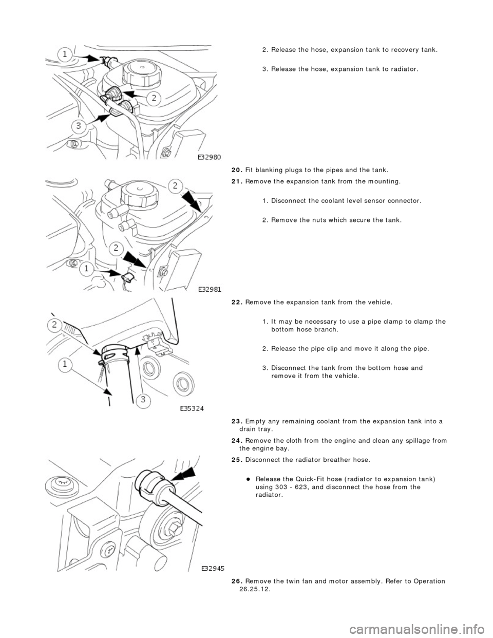
2. Release the hose, expansion tank to recovery tank.
3. Release the hose, expansion tank to radiator.
20. Fit blanking plugs to the pipes and the tank.
21. Remove the expansion tank from the mounting.
1. Disconnect the coolant level sensor connector.
2. Remove the nuts which secure the tank.
22. Remove the expansion tank from the vehicle.
1. It may be necessary to us e a pipe clamp to clamp the
bottom hose branch.
2. Release the pipe clip an d move it along the pipe.
3. Disconnect the tank from the bottom hose and remove it from the vehicle.
23. Empty any remaining coolant from the expansion tank into a
drain tray.
24. Remove the cloth from the engine and clean any spillage from
the engine bay.
25. Disconnect the radiator breather hose.
Release the Quick-Fit hose (radiator to expansion tank)
using 303 - 623, and disconnect the hose from the
radiator.
26. Remove the twin fan and motor assembly. Refer to Operation
26.25.12.
Page 901 of 2490
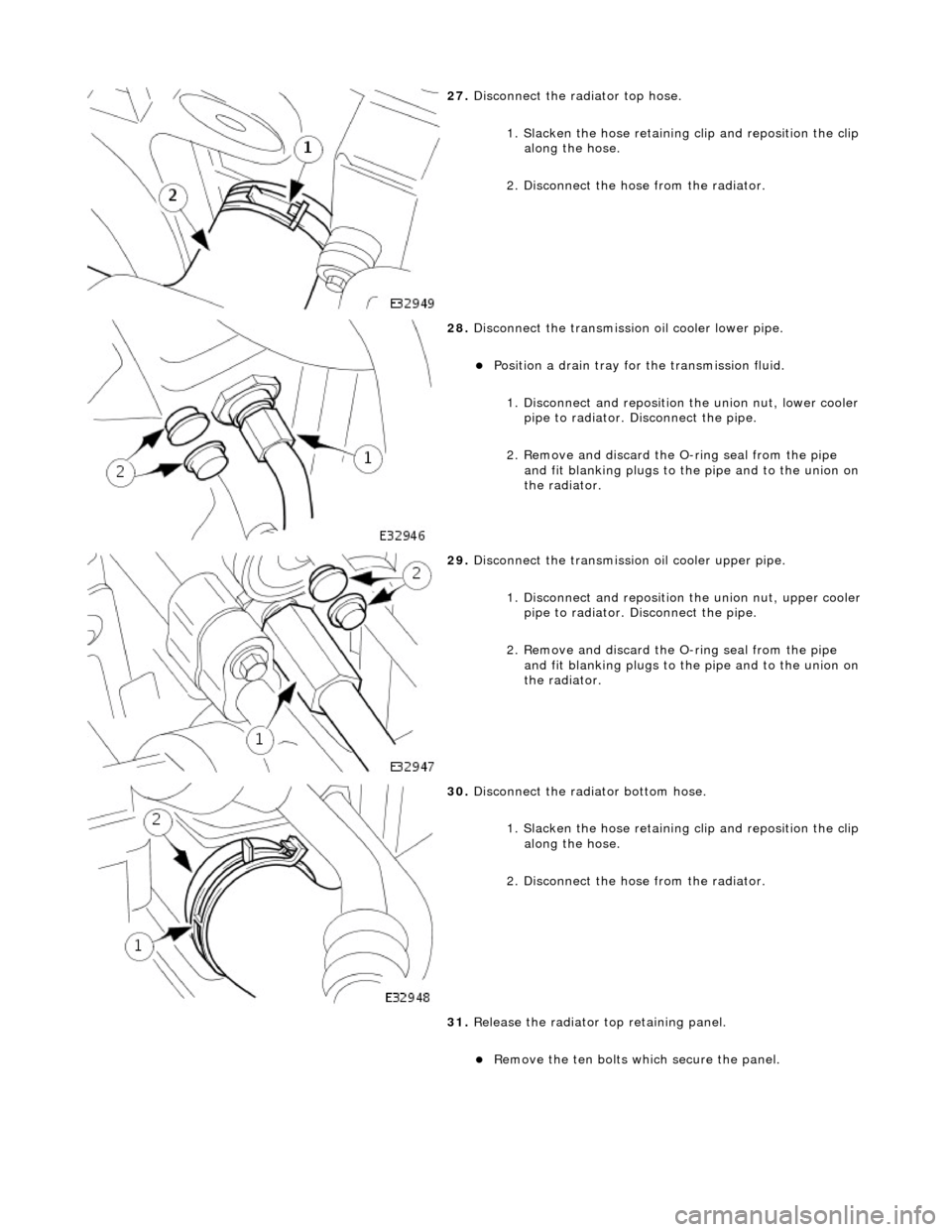
27. Disconnect the radiator top hose.
1. Slacken the hose retaining clip and reposition the clip
along the hose.
2. Disconnect the hose from the radiator.
28. Disconnect the transmission oil cooler lower pipe.
Position a drain tray for the transmission fluid.
1. Disconnect and reposition the union nut, lower cooler pipe to radiator. Di sconnect the pipe.
2. Remove and discard the O- ring seal from the pipe
and fit blanking plugs to the pipe and to the union on
the radiator.
29. Disconnect the transmission oil cooler upper pipe.
1. Disconnect and reposition the union nut, upper cooler pipe to radiator. Di sconnect the pipe.
2. Remove and discard the O- ring seal from the pipe
and fit blanking plugs to the pipe and to the union on
the radiator.
30. Disconnect the radiator bottom hose.
1. Slacken the hose retaining clip and reposition the clip
along the hose.
2. Disconnect the hose from the radiator.
31. Release the radiator top retaining panel.
Remove the ten bolts which secure the panel.
Page 902 of 2490
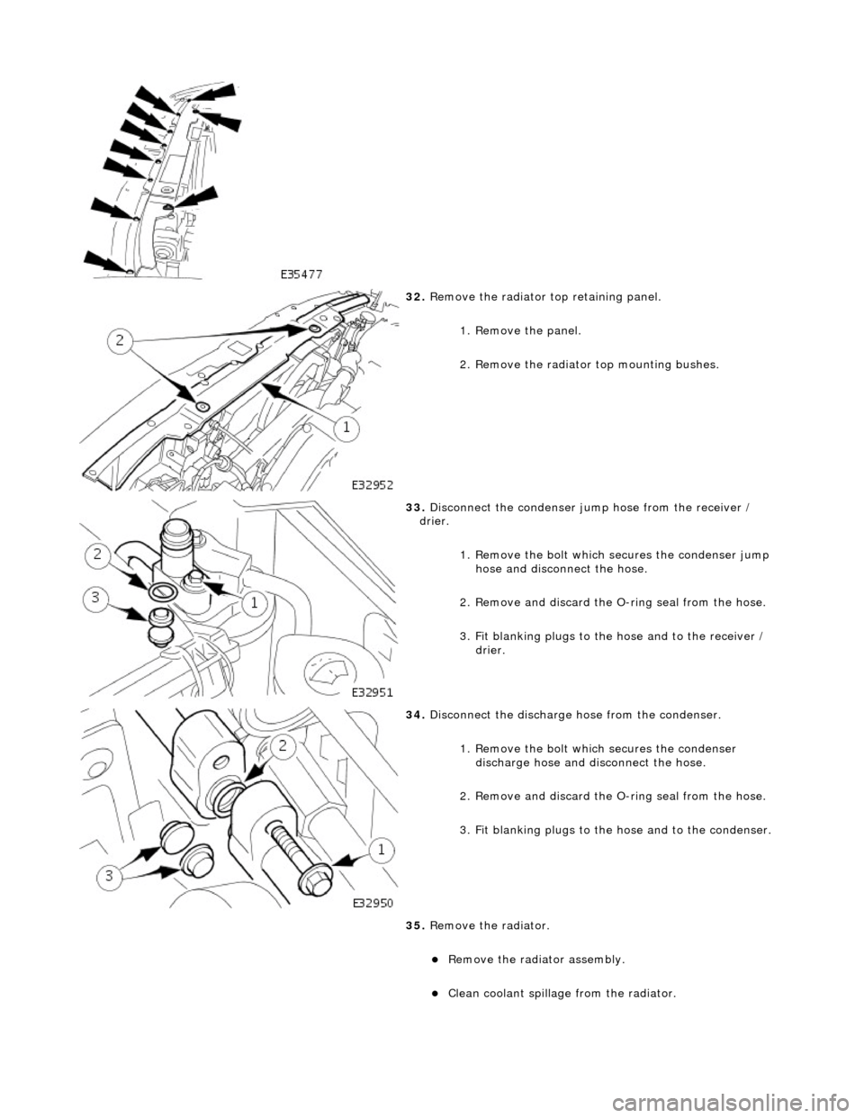
32. Remove the radiator top retaining panel.
1. Remove the panel.
2. Remove the radiator top mounting bushes.
33. Disconnect the condenser jump hose from the receiver /
drier.
1. Remove the bolt which secures the condenser jump hose and discon nect the hose.
2. Remove and discard the O-ring seal from the hose.
3. Fit blanking plugs to the hose and to the receiver / drier.
34. Disconnect the discharge hose from the condenser.
1. Remove the bolt which secures the condenser discharge hose and disconnect the hose.
2. Remove and discard the O-ring seal from the hose.
3. Fit blanking plugs to the hose and to the condenser.
35. Remove the radiator.
Remove the radiator assembly.
Clean coolant spillage from the radiator.
Page 903 of 2490
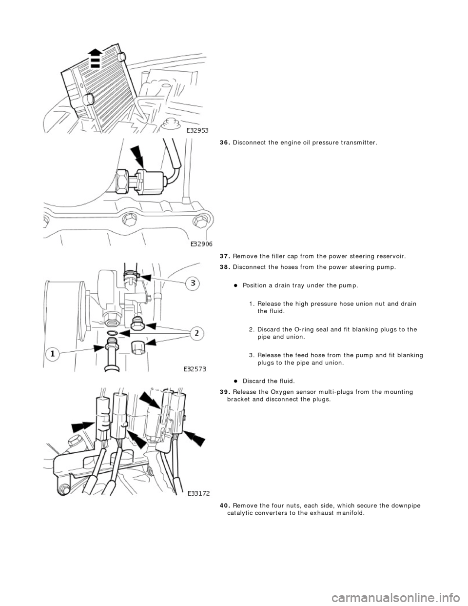
36. Disconnect the engine oi l pressure transmitter.
37. Remove the filler cap from the power steering reservoir.
38. Disconnect the hoses from the power steering pump.
Position a drain tray under the pump.
1. Release the high pressure hose union nut and drain the fluid.
2. Discard the O-ring seal an d fit blanking plugs to the
pipe and union.
3. Release the feed hose from the pump and fit blanking
plugs to the pipe and union.
Discard the fluid.
39. Release the Oxygen sensor multi-plugs from the mounting
bracket and disconnect the plugs.
40. Remove the four nuts, each side, which secure the downpipe
catalytic converters to the exhaust manifold.