Connector JAGUAR X308 1998 2.G Workshop Manual
[x] Cancel search | Manufacturer: JAGUAR, Model Year: 1998, Model line: X308, Model: JAGUAR X308 1998 2.GPages: 2490, PDF Size: 69.81 MB
Page 1845 of 2490
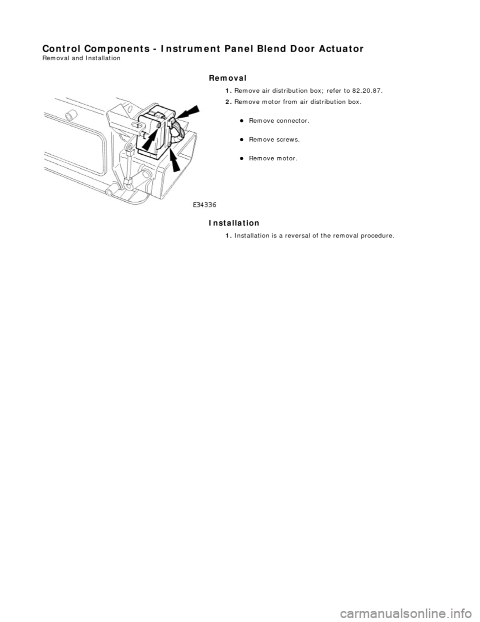
Control Components - Instrument Panel Blend Door Actuator
Removal and Installation
Removal
Installation
1.
Remove air distribution box; refer to 82.20.87.
2. Remove motor from air distribution box.
пЃ¬Remove connector.
пЃ¬Remove screws.
пЃ¬Remove motor.
1. Installation is a reversal of the removal procedure.
Page 1853 of 2490
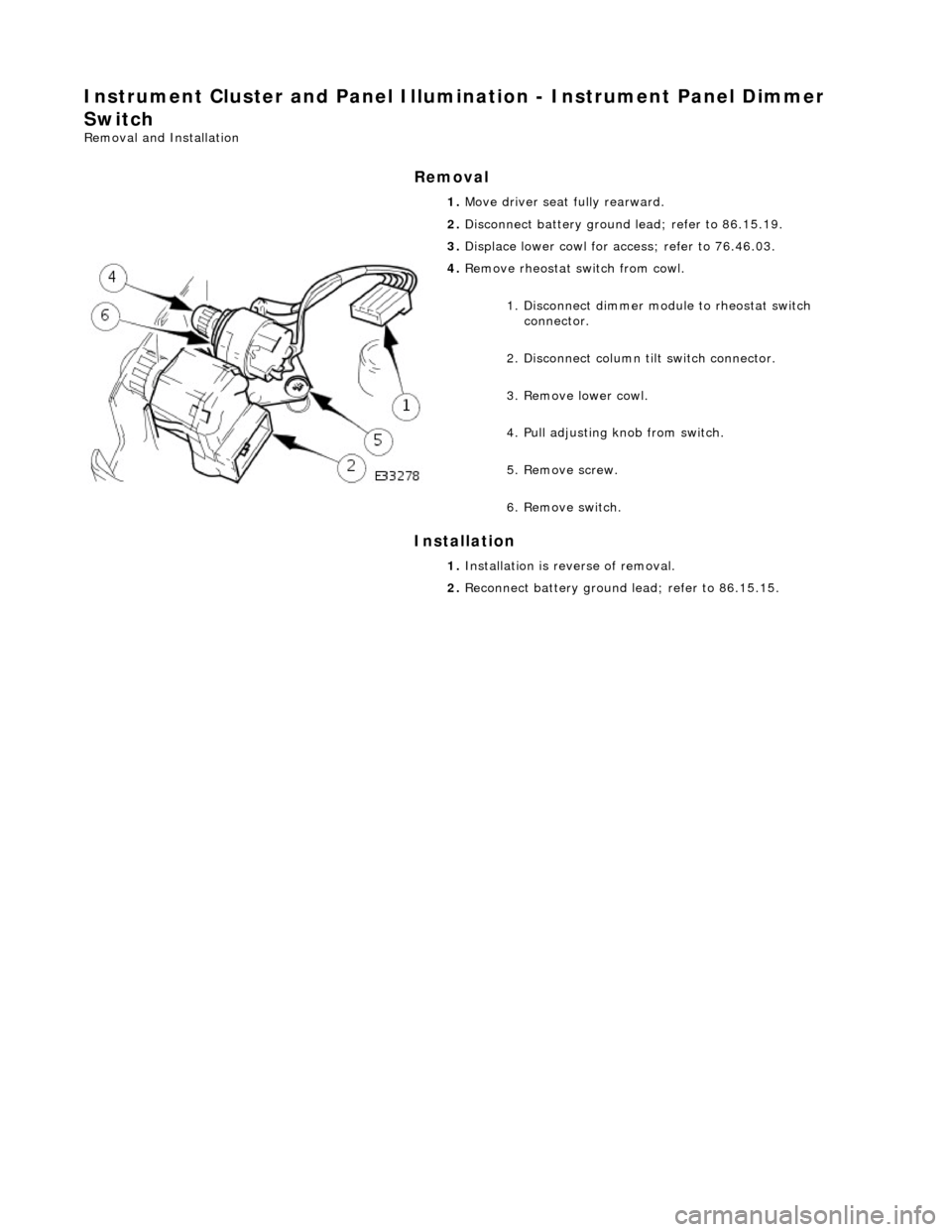
Instrument Cluster and Panel Illumination - Instrument Panel Dimmer
Switch
Removal and Installation
Removal
Installation
1.
Move driver seat fully rearward.
2. Disconnect battery ground lead; refer to 86.15.19.
3. Displace lower cowl for access; refer to 76.46.03.
4. Remove rheostat sw itch from cowl.
1. Disconnect dimmer module to rheostat switch connector.
2. Disconnect column tilt switch connector.
3. Remove lower cowl.
4. Pull adjusting knob from switch.
5. Remove screw.
6. Remove switch.
1. Installation is reverse of removal.
2. Reconnect battery ground lead; refer to 86.15.15.
Page 1856 of 2490

Instrument Cluster - Ins
trument Cluster
D
iagn
osis and Testing
Tests U
s
ing the Portable Diagnostic Unit
Re
fe
r to PDU User Guide
The c
o
mplexity of the electronics involved with the Instrument Cluster and the two multiplexed communication networks
which are connected to it, preclude the use of workshop genera l electrical test equipment. Therefore, reference should be
made to the PDU User Guide for detailed instructions on testing the Instrument Clus ter and associated circuits.
The PDU systematically test s and analyses all functions of the Instrument Clus ter, the various systems controlled by it and
individual sensors which are attached to each separate system.
Where a fault involving a remote sensor e. g. water temperature sensor, is indicated, before replacing the component, some
basic diagnostic methods may be necessary to confirm that connections are good and that wiring is not damaged.
Diagnostics using the PDU is via the CAN network, accessed at the diagnostic connector on the car.
Replaceable Parts
The only replaceable part s
are, General Illumination Bulbs, Direction Indicator Warning Bu
lbs and Main Beam Warning Bulb,
which are all of the conventional filament type. Other warning lamps are LEDs and are not replaceable.
Page 1867 of 2490
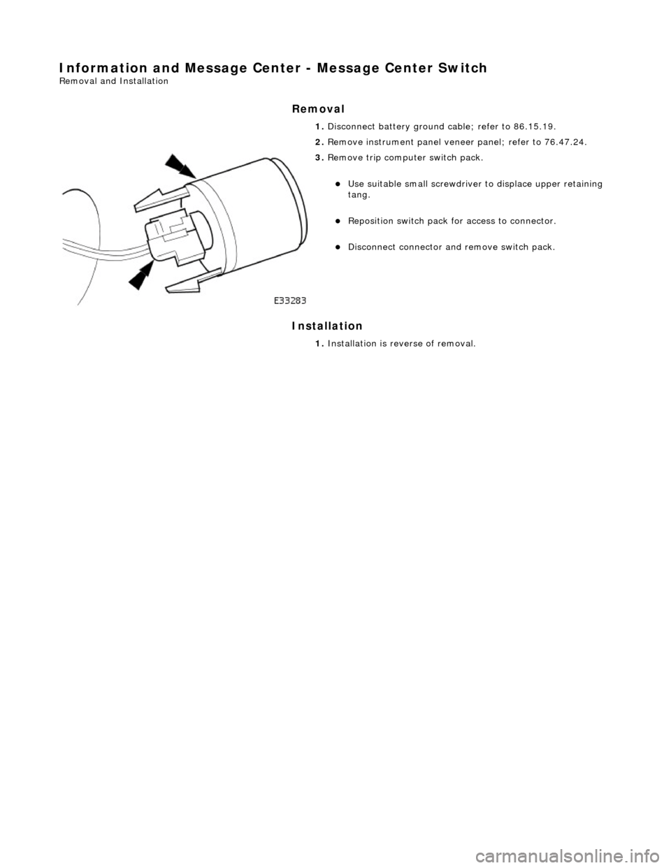
Information and Message Center - Message Center Switch
Removal and Installation
Removal
Installation
1.
Disconnect battery ground cable; refer to 86.15.19.
2. Remove instrument panel veneer panel; refer to 76.47.24.
3. Remove trip computer switch pack.
пЃ¬Use suitable small screwdriver to displace upper retaining
tang.
пЃ¬Reposition switch pack for access to connector.
пЃ¬Disconnect connector and remove switch pack.
1. Installation is reverse of removal.
Page 1869 of 2490

The functi
on of the parking aid is to prov
ide an audible warning to the driver of the distance to obstacles near the rear
bumper of the vehicle when parking or travelling at a slow sp eed. The system provides an assistance to the driver when
parking in order to help avoid collision with obstacles.
The sensor range at the rear of the vehicl e should be 1.8 meters. This should extend the full width of the rear bumper and
reduce to 50 cm at the vehicle co rners. The vertical range is adequate to protec t the highest and lowest points of the rear of
the vehicle. The system will detect curbs with heights of at least 18 cm. Obstacles, such as curbs, that are low enough to
pass under the vehicle until they make contact with the tires will not be detected.
The system activates a specific speaker with a tone signifying the distance to the obstacle. The tone consists of a beep and
defined space ratio which varies depending on the calculated distance. When the distance to the obstacle is less than 20 cm
the speaker tone is continuous.
The parking aid is continuously in operation, unless towing wh en the system automatically switches off. If the reverse aid
develops a fault the tone will sound continuously for three seconds when the igni tion is switched on or the reverse gear is
selected.
The parking aid system comprises of:
пЃ¬a
module mounted in the batte
ry junction box (BJB).
пЃ¬fou
r rear bumper mounted sensors which have a 90В° angled electrical connector.
пЃ¬an audible speaker, moun
ted on
the rear parcel shelf.
It
em
Par
t Number
De
scription
1—Parkin
g aid module
2—Rear
parking aid speaker
3—Rear
parking aid sensors
Page 1870 of 2490

Parking Aid - Parking Aid
Diagnosis and Testing
Inspection and Verification
1.1. Verify the customer concern.
2. 2. Visually inspect for obvious signs of mechanical or electrical damage.
Visual Inspection Chart
3. 3. If an obvious cause for an observed or reported concern is found, correct the cause (if possible) before proceeding to the next step
4. 4. If the cause is not visually evident, verify the sympto m and refer to the Jaguar approved diagnostic system.
Electrical
пЃ¬Fuse(s) пЃ¬Relay(s) пЃ¬Wiring Harness пЃ¬Electrical connector(s) пЃ¬Rear parking aid sensor(s) пЃ¬Rear parking aid speaker пЃ¬Reversing lamp switch пЃ¬Parking aid module
Page 1872 of 2490
Installation
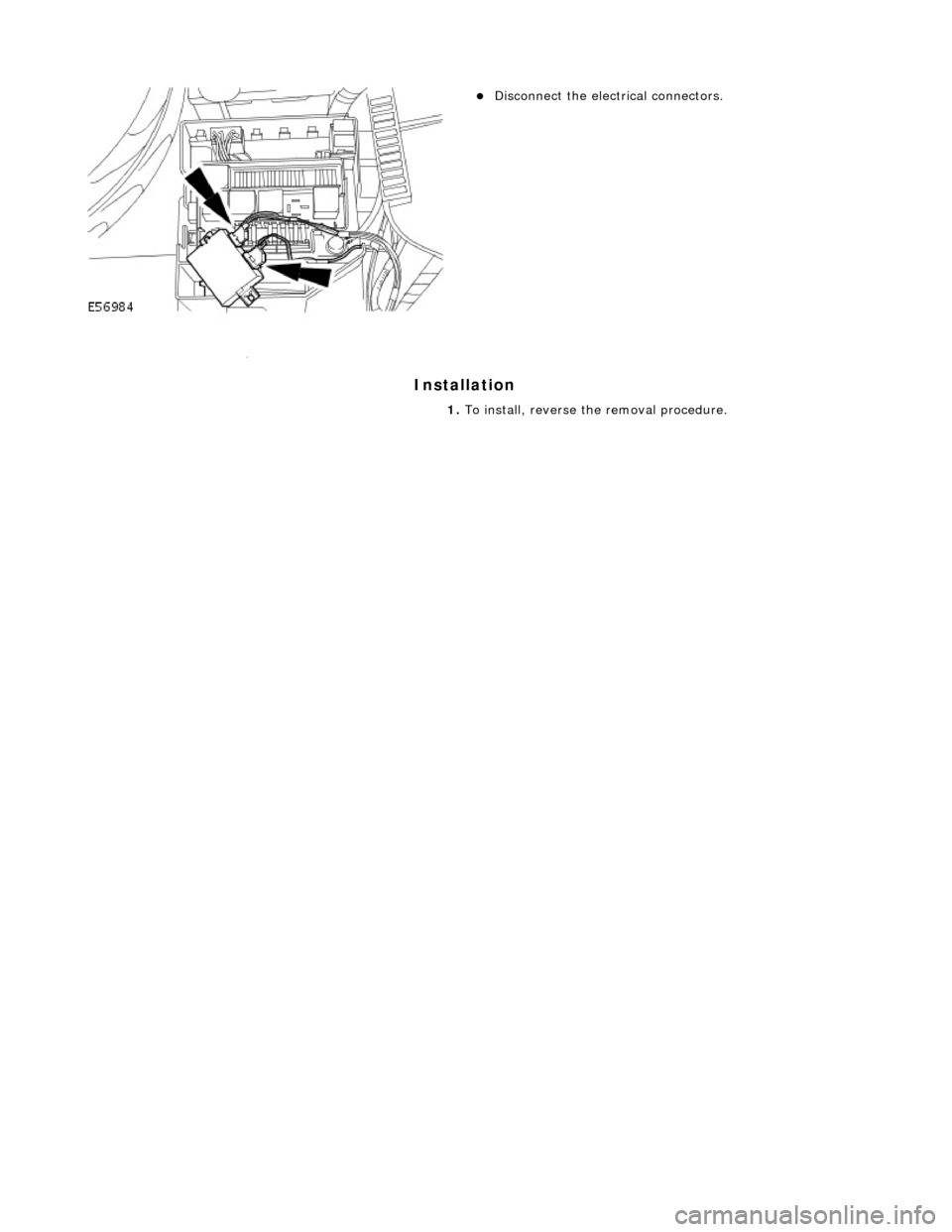
пЃ¬Disconnect the electrical connectors.
1. To install, reverse the removal procedure.
Page 1873 of 2490

Parking Aid - Rear Parking Aid Sensor
Removal and Installation
Removal
Installation
1.
Raise and support the vehicle.
For additional information, refer to: Jacking
(100-02 Jacking
and Lifting, Descript ion and Operation).
2. Disconnect the electrical connector.
3. CAUTION: Make sure excessiv e pressure or tools are not
used when removing the parkin g aid sensor from the housing.
Remove the rear parking aid sensor.
1. To install, reverse the removal procedure.
Page 1874 of 2490

Parking Aid - Rear Parking Aid Speaker
Removal and Installation
Removal
Installation
1.
Remove the parcel shelf.
For additional information, refer to: Parcel Shelf
(501-05
Interior Trim and Ornamentatio n, Removal and Installation).
2. Reposition the sound insulation.
3. Disconnect the electrical connector.
4. Remove the rear parking aid speaker.
1. To install, reverse the removal procedure.
Page 1888 of 2490

detectable difference in the voltage reading (due to minimal current flow); if there is a detectable difference, clean the cable terminal and the adjacent area of the body.
When the voltage has been measured, STOP THE ENGINE.
Reconnect the battery or fit a new battery if it was established that the battery was at fault (Refer to 414-01).
If the cooling fans operate during the above test, the large demand of current will overload the generator and cause the
engine to stall.
If the battery is in a low state of charge the voltage will rise momentarily when the battery is disconnected. However, the
maximum that the voltage can increase to with this new gene rator is 25V and then only for a maximum time of 200 mS.
Using a Substitute Battery
A substitute battery may be fitted for the tests. This batter y must be a known good example and must have been off-charge for at least twelve hours, with a term inal voltage of approximately 12.8V.
Ensure that all electrical loads are swit ched OFF and that the engine is cool.
Start the engine and allow to IDLE.
Measure the voltage across the battery term inals. It should have dropped a little due to the large start current and then
risen to a value of between 13V and 15V.
If the above test (whichever one used) indicates that the generator is not working then the connections on the rear face of
the generator should be checked. If there is a faulty connection, then the ge nerator will not perform correctly no matter
how fast it is driven.
Checking Generator Connections
ItemDescription
1Multi-Plug Connector
2B+ Main Output Terminal