ECU JAGUAR X308 1998 2.G Workshop Manual
[x] Cancel search | Manufacturer: JAGUAR, Model Year: 1998, Model line: X308, Model: JAGUAR X308 1998 2.GPages: 2490, PDF Size: 69.81 MB
Page 1376 of 2490

2. Reposition the tank.
8. Install engine lifting bracket 303 - 536 at the rear LH.
9. Support the engine using 303 - 021.
1. Adjust and locate the stan ds in the LH and RH fender
channels and tighten the beam fixings.
2. Engage the support hook s in the lifting brackets.
3. Tighten the support hook adjusters and take the weight of the engine.
10. Raise the vehicle for access.
11. Remove the LH downpipe cata lytic converter (17.50.09).
12. Remove the front muffler (30.10.18).
13. Remove the RH downpipe catalytic converter (17.50.09 and
17.50.10).
14. Drain the transmission fluid, (44.24.02).
15. Locate a transmission jack, Epco V-100 or similar, under the
transmission unit.
Adjust the angle of the jack to suit the transmission.
Secure the side clamps.
Pass the safety chain over the transmission unit and
secure.
Page 1379 of 2490
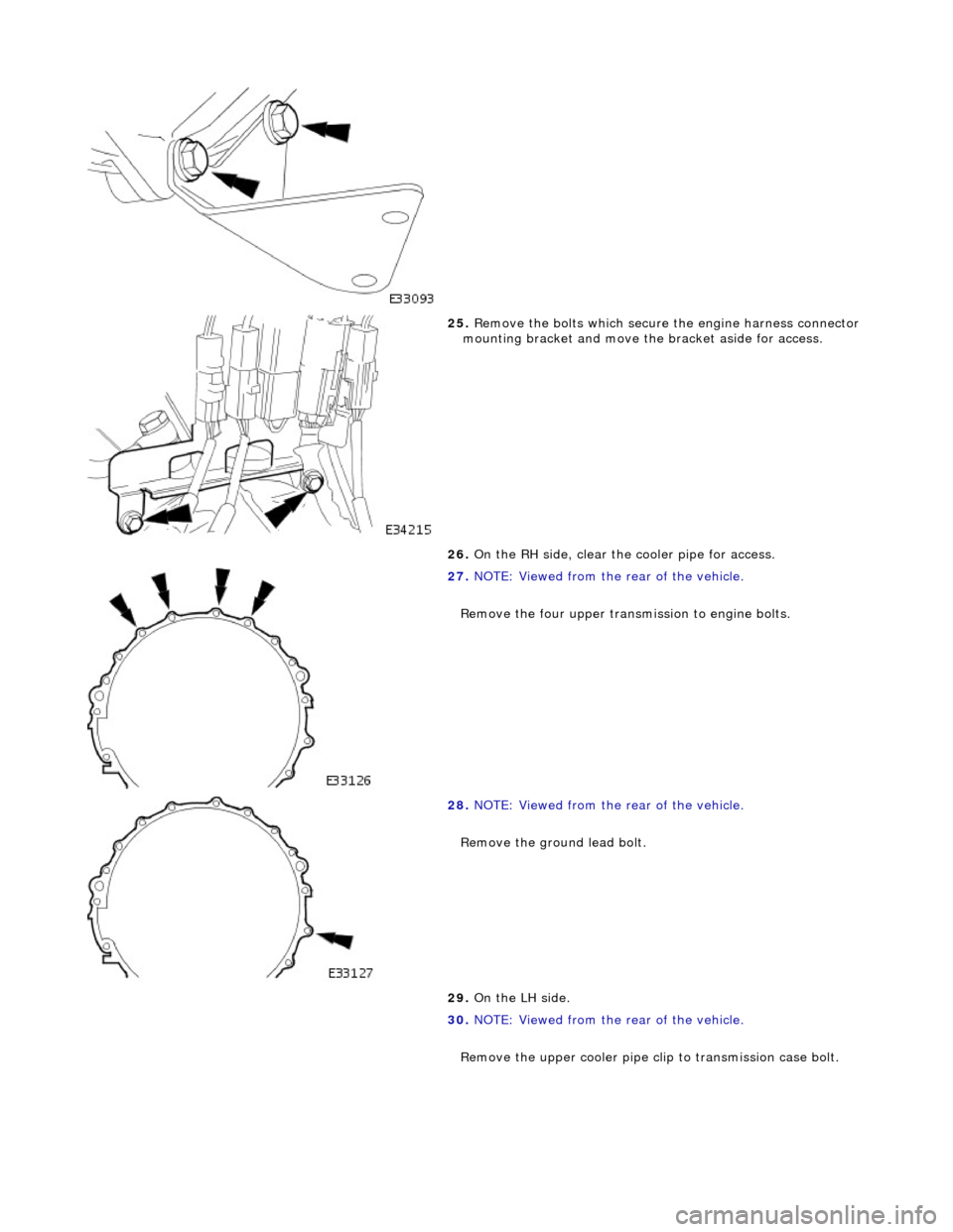
25. Remove the bolts which secure the engine harness connector
mounting bracket and move th e bracket aside for access.
26. On the RH side, clear the cooler pipe for access.
27. NOTE: Viewed from the rear of the vehicle.
Remove the four upper transmission to engine bolts.
28. NOTE: Viewed from the rear of the vehicle.
Remove the ground lead bolt.
29. On the LH side.
30. NOTE: Viewed from the rear of the vehicle.
Remove the upper cooler pipe c lip to transmission case bolt.
Page 1384 of 2490
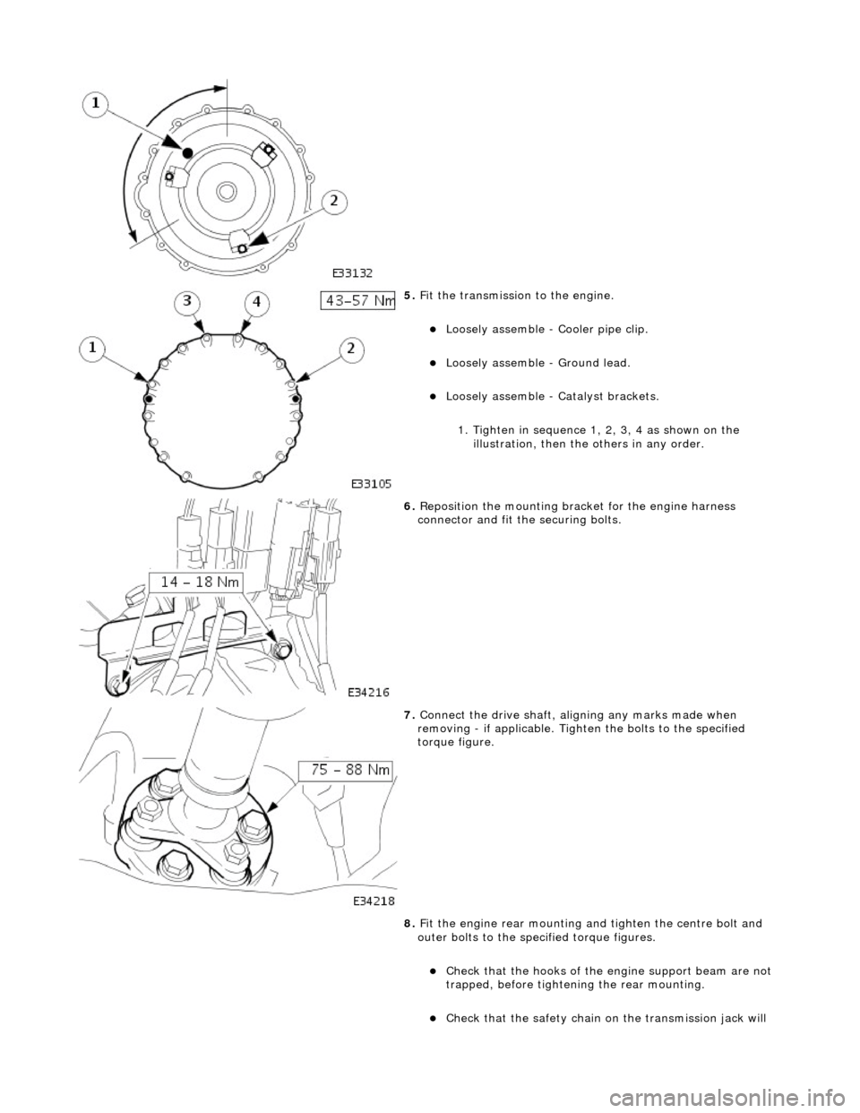
5. Fit the transmission to the engine.
Loosely assemble - Cooler pipe clip.
Loosely assemble - Ground lead.
Loosely assemble - Ca talyst brackets.
1. Tighten in sequence 1, 2, 3, 4 as shown on the illustration, then the others in any order.
6. Reposition the mounting brac ket for the engine harness
connector and fit the securing bolts.
7. Connect the drive shaft, aligning any marks made when
removing - if applicable. Tighten the bolts to the specified
torque figure.
8. Fit the engine rear mounting and tighten the centre bolt and
outer bolts to the specified torque figures.
Check that the hooks of the engine support beam are not
trapped, before tighteni ng the rear mounting.
Check that the safety chain on the transmission jack will
Page 1385 of 2490

not be trapped when the mounting is fitted.
9. Remove the transmission jack.
10. Fit the three bolts which secure the torque converter to the
drive plate.
1. Loosely assemble all three drive plate to torque converter bolts. Whilst preventing crankshaft
rotation, tighten the three converter bolts to the
specified torque figure.
2. Fit the blanking plug.
11. Connect the transmission harness multiplug.
1. Engage the multiplug.
2. Rotate the locking lever to secure.
12. Connect the selector cable to the selector lever and fit the
abutment bracket to the transmission casing. Tighten the nut
and two bolts to the specified torque figure.
Page 1387 of 2490
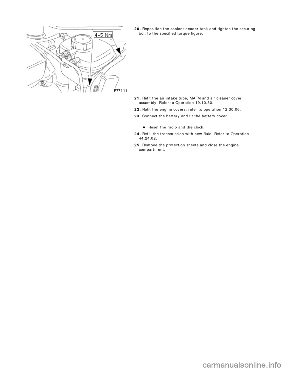
20. Reposition the coolant header tank and tighten the securing
bolt to the specified torque figure.
21. Refit the air intake tube, MAFM and air cleaner cover
assembly. Refer to Operation 19.10.30.
22. Refit the engine covers. re fer to operation 12.30.06.
23. Connect the battery and fit the battery cover..
Reset the radio and the clock.
24. Refill the transmission with new fluid. Refer to Operation
44.24.02.
25. Remove the protection sheets and close the engine
compartment.
Page 1391 of 2490
In the event of a system fault, the TCM will adopt 'limp home' mode.
Electrical control
Refer to Section 307-01B.
Transmission Control Components
Transmission Control Module (TCM)
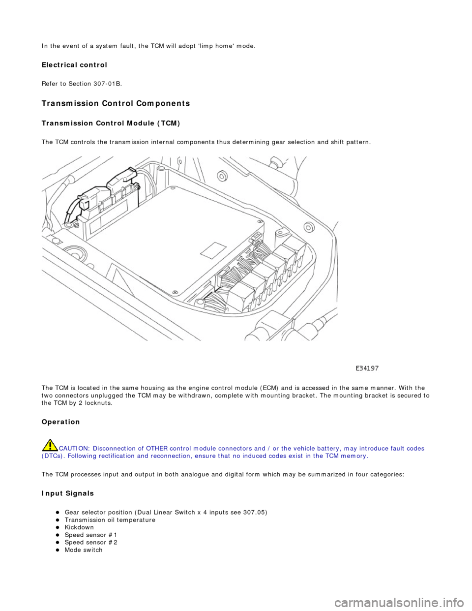
The TCM controls the transmission internal components thus determining gear selection and shift pattern.
The TCM is located in the same housing as the engine control module (ECM) and is accessed in the same manner. With the
two connectors unplugged the TCM may be withdrawn, complete with mounting bracket. The mounting bracket is secured to
the TCM by 2 locknuts.
Operation
CAUTION: Disconnection of OTHER contro l module connectors and / or the vehicle battery, may introduce fault codes
(DTCs). Following rectification and reconnection, ensu re that no induced codes exist in the TCM memory.
The TCM processes input and output in both analogue and di gital form which may be summarized in four categories:
Input Signals
Gear selector position (Dual Linear Switch x 4 inputs see 307.05) Transmission oil temperature Kickdown Speed sensor #1 Speed sensor #2 Mode switch
Page 1392 of 2490
CAN Input Signals
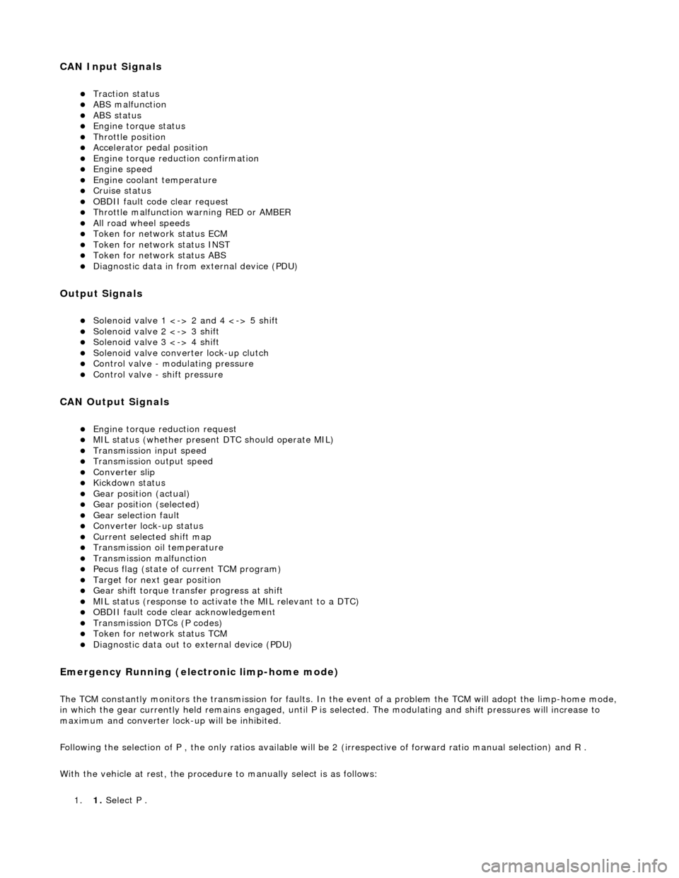
Traction status ABS malfunction ABS status Engine torque status Throttle position Accelerator pedal position Engine torque reduction confirmation Engine speed Engine coolant temperature Cruise status OBDII fault code clear request Throttle malfunction warning RED or AMBER All road wheel speeds Token for network status ECM Token for network status INST Token for network status ABS Diagnostic data in from external device (PDU)
Output Signals
Solenoid valve 1 <-> 2 and 4 <-> 5 shift Solenoid valve 2 <-> 3 shift Solenoid valve 3 <-> 4 shift Solenoid valve converter lock-up clutch Control valve - modulating pressure Control valve - shift pressure
CAN Output Signals
Engine torque reduction request MIL status (whether present DTC should operate MIL) Transmission input speed Transmission output speed Converter slip Kickdown status Gear position (actual) Gear position (selected) Gear selection fault Converter lock-up status Current selected shift map Transmission oil temperature Transmission malfunction Pecus flag (state of current TCM program) Target for next gear position Gear shift torque transfer progress at shift MIL status (response to activate the MIL relevant to a DTC) OBDII fault code clear acknowledgement Transmission DTCs (P codes) Token for network status TCM Diagnostic data out to external device (PDU)
Emergency Running (elect ronic limp-home mode)
The TCM constantly monitors the transmissi on for faults. In the event of a problem the TCM will adopt the limp-home mode, in which the gear currently held remains engaged, until P is selected. The modulati ng and shift pressures will increase to
maximum and converter lock-up will be inhibited.
Following the selection of P , the only ratios available will be 2 (irrespective of forward ratio manual selection) and R .
With the vehicle at rest, the procedure to manually select is as follows:
1. 1. Select P .
Page 1433 of 2490

Automatic Transmission/Transaxle - 4.0L SC V8 - AJ26 - Extension
Housing Seal
In-vehicle Repair
Removal
Special Tool(s)
Oil seal replacer
307-378
Driveshaft wrench
205-053
1. Disconnect the battery ground lead.
2. Select N and choc the road wheels.
3. Remove the front muffler, re fer to Operation 30.10.18.
4. Remove the engine rear mounting bracket.
1. Support the transmission.
2. Remove the bolt, engine rear mounting to transmission.
3. Remove the four bolts which secure the mounting
cross member to the body.
5. Detach the driveshaft from th e transmission drive flange.
1. If the transmission is to be refitted, mark the position of the coupling relative to the drive flange.
5. CAUTION: Under no circ umstances remove the
driveshaft to flexible coupling fixings.
2. Remove the three bolts, tr ansmission drive flange to
flexible coupling.
6. Secure the driveshaft wrench 205 - 053 to the output shaft
flange.
Page 1435 of 2490

the specified torque figure.
2. Stake the nut to the output shaft.
4. Refit the bolts securing the dr iveshaft and tighten to the
specified torque figure.
5. Refit the the rear mounting crossmember and tighten the
securing bolts to the specified torque figures.
6. Refer to Operation 44.24.02 for fluid fill procedure.
7. Check for leaks and remove spilt fluid.
Page 1438 of 2490

Installation
13. Remove the valve body assembly.
Remove the nine bolts which re tain the valve body to the
transmission case.
1. Installation is the re verse of the removal procedure, noting the
following:
2. Clean all mating faces and relevant parts.
3. Tighten the nine bolts securing the valve body, to the specified
torque figure.
4. Refit the dowel (leaf spring to valve body) and the leaf spring.
Fit and tighten the securing bolt to the specified torque figure.
5. Tighten the centre retaining bolt of the electrical connector to
the specified torque figure.