engine JAGUAR X308 1998 2.G Workshop Manual
[x] Cancel search | Manufacturer: JAGUAR, Model Year: 1998, Model line: X308, Model: JAGUAR X308 1998 2.GPages: 2490, PDF Size: 69.81 MB
Page 1520 of 2490

moving the set position of either the gear selector lever or the selector lever on the transmission casing.
3. Tighten to 22-28 Nm.
4. Verify the 'N' setting.
6. Check that all released connec tors are safely insulated and
connect the vehicle battery.
7. Switch ON the ignition.
8. Adjust the position of the linear switch so that the selector 'N'
position graphic illuminates. Ti ghten the four screws to 0,7-1
Nm.
9. Move the gear selector to 'R' to confirm that the 'R' position
graphic illuminates.
10. Check that the engine will start when the gear selector is in
the 'N' and 'P' positions, bu t not in any other position.
11. Move the gear selector to 'N'.
12. Switch OFF the ignition.
13. Disconnect the battery.
14. Install the console assembly, operation 76.25.01.
15. Install the console finisher veneer panel, operation 76.47.26.
16. Install the J-gate surround, operation 76.25.24.
17. Perform the Battery Reconnection Procedure described in
Operation 86.15.15.
Page 1524 of 2490

All vehicles are fitted with a stainless steel exhaust system which features:
пЃ¬Low back-pressure gas flow. пЃ¬Catalytic converters for mark ets having unleaded fuel. пЃ¬Front muffler common to the left-hand and right-hand engine cylinder banks.
Downpipe Catalytic Converter Assembly
Page 1525 of 2490
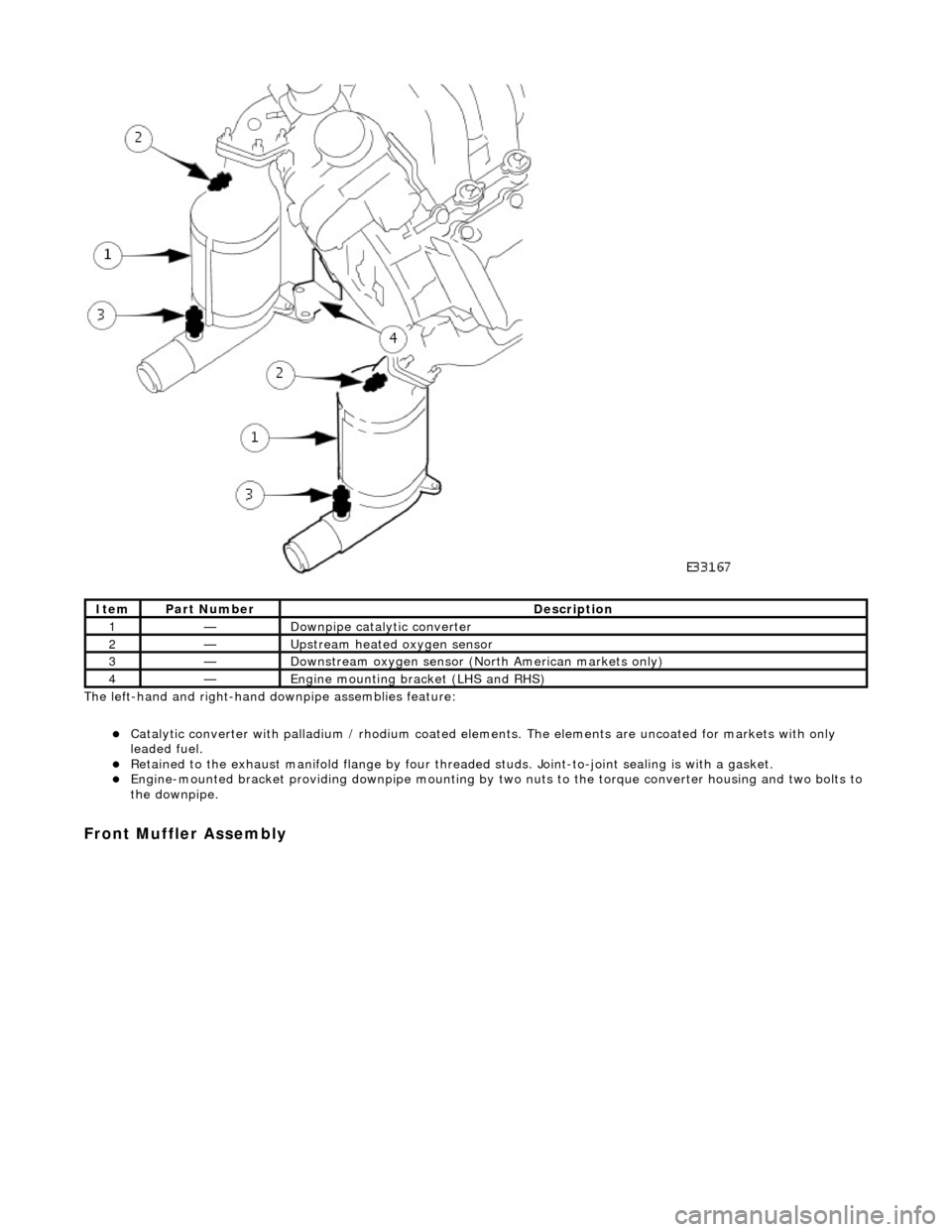
The left-hand and right-hand do wnpipe assemblies feature:
пЃ¬Catalytic converter with palladium / rhodium coated elem ents. The elements are uncoated for markets with only
leaded fuel.
пЃ¬Retained to the exhaust manifold flange by four thread ed studs. Joint-to-joint sealing is with a gasket. пЃ¬Engine-mounted bracket providing downpipe mounting by two nuts to the torque converter housing and two bolts to
the downpipe.
Front Muffler Assembly
ItemPart NumberDescription
1—Downpipe catalytic converter
2—Upstream heated oxygen sensor
3—Downstream oxygen sensor (North American markets only)
4—Engine mounting bracket (LHS and RHS)
Page 1526 of 2490

The front muffler assembly features:
пЃ¬Twin-pipe absorption type muffler. пЃ¬Pipe-to-pipe pres sure damping. пЃ¬Inlet and outlet pipes welded to the muffler. пЃ¬Front joints are flanged on supercharged engines and a flexible pipe (not removable separately ) is fitted behind each
flange - refer to the inset above.
Intermediate Muffler Assembly
The left- and right-hand intermedia te muffler assemblies comprise:
пЃ¬Absorption type muffler. пЃ¬Inlet and outlet pipes welded to the muffler.
Page 1531 of 2490
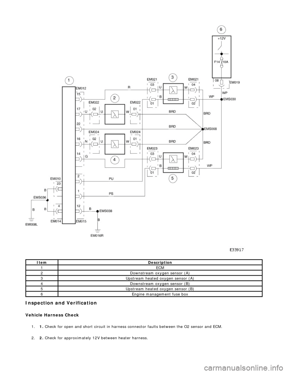
Inspection and Verification
Vehicle Harness Check
1.1. Check for open and short circuit in harness conn ector faults between the O2 sensor and ECM.
2. 2. Check for approximately 12V between heater harness.
ItemDescription
1ECM
2Downstream oxygen sensor (A)
3Upstream heated oxygen sensor (A)
4Downstream oxygen sensor (B)
5Upstream heated oxygen sensor (B)
6Engine management fuse box
Page 1532 of 2490

Heater Resistance Check
1.1. Verify that the resistance between the heater term inals is between 4OHM and 10OHM at -20В°C to 100В°C.
Performance Check
1.1. Run the engine at 2500 RPM for two minutes, to heat up the O2 sensor.
2. 2. Check the voltage of the sensor output: Alternates between less than 0.4V at feed back engine conditions and in
excess of 0.5V, see graph.
These voltages are for reference only.
3. 3. Check that cycle of the upstream se nsor output is in accordance with the appropriate pinpoint test.
4. 4. Check that cycle of the downstream sensor output is in accordance with the appropriate pinpoint test.
Page 1535 of 2490
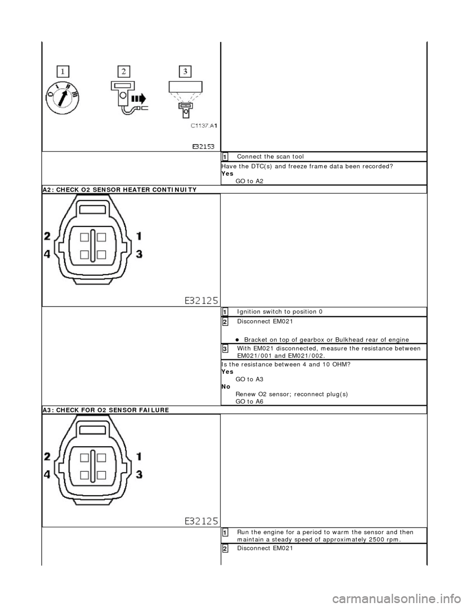
Connect the scan tool 1
Have the DTC(s) and freeze frame data been recorded?
Yes GO to A2
A2: CHECK O2 SENSOR HEATER CONTINUITY
Ignition switch to position 0 1
Disconnect EM021
пЃ¬Bracket on top of gearbox or Bulkhead rear of engine
2
With EM021 disconnected, measure the resistance between
EM021/001 and EM021/002. 3
Is the resistance between 4 and 10 OHM?
Yes
GO to A3
No Renew O2 sensor; reconnect plug(s)
GO to A6
A3: CHECK FOR O2 SENSOR FAILURE
Run the engine for a period to warm the sensor and then
maintain a steady speed of approximately 2500 rpm. 1
Disconnect EM021 2
Page 1536 of 2490
пЃ¬Bracket on top of gearbox or Bulkhead rear of engine
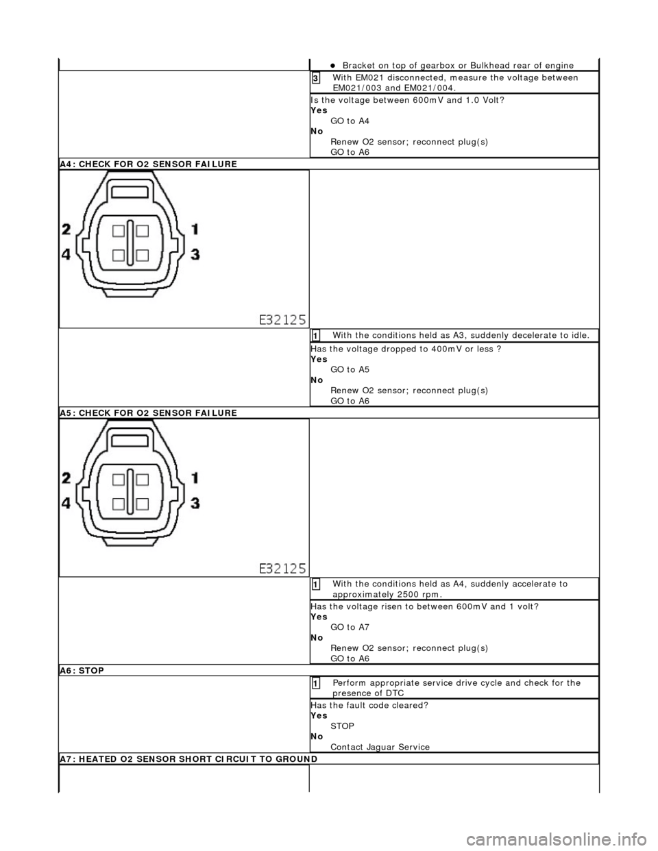
With EM021 disconnected, measure the voltage between
EM021/003 and EM021/004. 3
Is the voltage between 600mV and 1.0 Volt?
Yes
GO to A4
No Renew O2 sensor; reconnect plug(s)
GO to A6
A4: CHECK FOR O2 SENSOR FAILURE
With the conditions held as A3, suddenly decelerate to idle. 1
Has the voltage dropped to 400mV or less ?
Yes GO to A5
No Renew O2 sensor; reconnect plug(s)
GO to A6
A5: CHECK FOR O2 SENSOR FAILURE
With the conditions held as A4, suddenly accelerate to
approximately 2500 rpm. 1
Has the voltage risen to between 600mV and 1 volt?
Yes GO to A7
No Renew O2 sensor; reconnect plug(s)
GO to A6
A6: STOP
Perform appropriate service drive cycle and check for the
presence of DTC 1
Has the fault code cleared?
Yes STOP
No Contact Jaguar Service
A7: HEATED O2 SENSOR SHORT CIRCUIT TO GROUND
Page 1546 of 2490
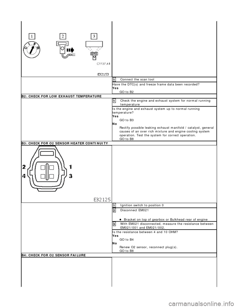
Connect the scan tool 1
Have the DTC(s) and freeze frame data been recorded?
Yes GO to B2
B2: CHECK FOR LOW EX HAUST TEMPERATURE
Check the engine and exhaust system for normal running
temperature 1
Is the engine and exhaust sy stem up to normal running
temperature?
Yes GO to B3
No Rectify possible leaking exhaust manifold / catalyst, general
causes of an over rich mixture and engine cooling system
operation. Test the system for correct operation.
GO to B8
B3: CHECK FOR O2 SENS OR HEATER CONTINUITY
Ignition switch to position 0 1
Disconnect EM021
пЃ¬Bracket on top of gearbox or Bulkhead rear of engine
2
With EM021 disconnected, measure the resistance between
EM021/001 and EM021/002. 3
Is the resistance between 4 and 10 OHM?
Yes
GO to B4
No Renew O2 sensor, reconnect plug(s).
GO to B8
B4: CHECK FOR O2 SENSOR FAILURE
Page 1547 of 2490

Run the engine for a period to warm the sensor and then
maintain a steady speed of approximately 2500 rpm. 1
Measure the voltage between EM021/003 and EM021/004. 2
Is the voltage between 600mV and 1.0 Volt?
Yes
GO to B5
No Renew O2 sensor, reconnect plug(s).
GO to B8
B5: CHECK FOR O2 SENSOR FAILURE
With the conditions held as B4, suddenly decelerate to idle. 1
Has the voltage dropped to 400mV or less ?
Yes GO to B6
No Renew O2 sensor, reconnect plug(s).
GO to B8
B6: CHECK FOR O2 SENSOR FAILURE
With the conditions held as B5, suddenly accelerate to
approximately 2500 rpm. 1
Has the voltage risen to between 600mV and 1 volt?
Yes