engine JAGUAR X308 1998 2.G Workshop Manual
[x] Cancel search | Manufacturer: JAGUAR, Model Year: 1998, Model line: X308, Model: JAGUAR X308 1998 2.GPages: 2490, PDF Size: 69.81 MB
Page 1600 of 2490

Yes GO to F7
No Renew O2 sensor. Reconnect plug(s)
GO to F8
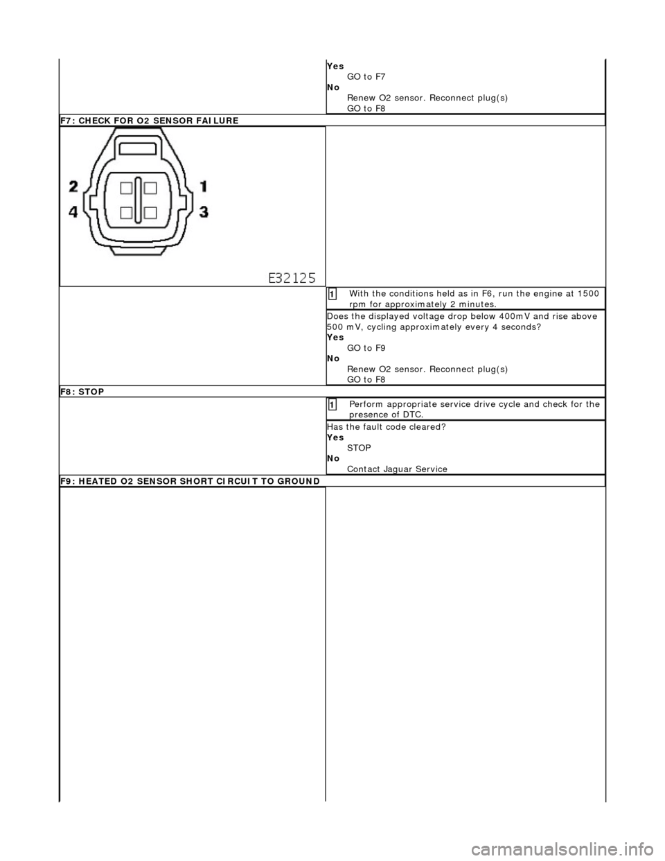
F7: CHECK FOR O2 SENSOR FAILURE
With the conditions held as in F6, run the engine at 1500
rpm for approximately 2 minutes. 1
Does the displayed voltage drop below 400mV and rise above
500 mV, cycling approximately every 4 seconds?
Yes GO to F9
No Renew O2 sensor. Reconnect plug(s)
GO to F8
F8: STOP
Perform appropriate service drive cycle and check for the
presence of DTC. 1
Has the fault code cleared?
Yes STOP
No Contact Jaguar Service
F9: HEATED O2 SENSOR SHORT CIRCUIT TO GROUND
Page 1610 of 2490

Connect the scan tool 1
Have the DTC(s) and freeze frame data been recorded?
Yes GO to G2
G2: CHECK FOR O2 SENSOR FAILURE
Run the engine for a period to warm the sensor and then
maintain a steady speed of approximately 2500 rpm. 1
Measure the voltage between EM024/001 and EM024/002. 2
Is the voltage between 600mV and 1.0 Volt?
Yes
GO to G3
No Renew O2 sensor and reconnect plug(s)
GO to G6
G3: CHECK FOR O2 SENSOR FAILURE
Page 1613 of 2490

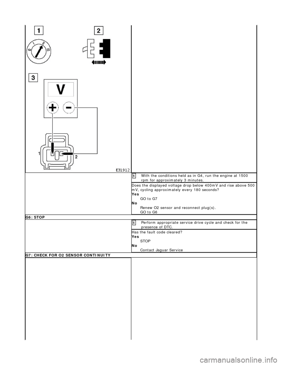
With the conditions held as in G4, run the engine at 1500
rpm for approximately 3 minutes. 1
Does the displayed voltage drop below 400mV and rise above 500
mV, cycling approximately every 180 seconds?
Yes GO to G7
No Renew O2 sensor and reconnect plug(s).
GO to G6
G6: STOP
Perform appropriate service drive cycle and check for the
presence of DTC. 1
Has the fault code cleared?
Yes STOP
No Contact Jaguar Service
G7: CHECK FOR O2 SENSOR CONTINUITY
Page 1625 of 2490

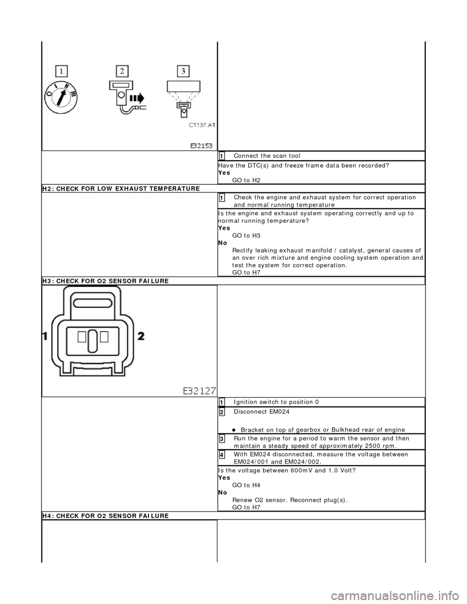
Conne
ct the scan tool
1
Have the DTC(s) and fr
eeze
frame data been recorded?
Yes GO to H2
H2: CHECK
FOR LOW EXHAUST TEMPERATURE
Chec
k the engine and exhaust
system for correct operation
and normal running temperature
1
Is th
e engine and exhaust system operating correctly and up to
normal running temperature?
Yes GO to H3
No Rectify leaking exhaust manifold / catalyst, general causes of
an over rich mixture and engine cooling system operation and
test the system for correct operation.
GO to H7
H
3: CHECK FOR O2 SENSOR FAILURE
I
gnition switch to position 0
1
Di
sconnect EM024
пЃ¬Bracket on top o
f gearbox or
Bulkhead rear of engine
2
R
un the engine for a period to
warm the sensor and then
maintain a steady speed of approximately 2500 rpm.
3
W
ith EM024 disconnected, measure the voltage between
EM024/001 and EM024/002.
4
Is
the voltage between 600mV and 1.0 Volt?
Yes GO to H4
No Renew O2 sensor. Reconnect plug(s).
GO to H7
H
4: CHECK FOR O2 SENSOR FAILURE
Page 1626 of 2490

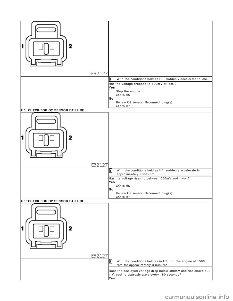
With
the conditions held as H3, suddenly decelerate to idle.
1
Has the voltage
d
ropped to 400mV or less ?
Yes Stop the engine
GO to H5
No Renew O2 sensor. Reconnect plug(s).
GO to H7
H5
: CHECK FOR O2 SENSOR FAILURE
Wi
th
the conditions held as H4, suddenly accelerate to
approximately 2500 rpm.
1
Has the
voltage risen to between 600mV and 1 volt?
Yes GO to H6
No Renew O2 sensor. Reconnect plug(s).
GO to H7
H6
: CHECK FOR O2 SENSOR FAILURE
W
i
th the conditions held as in H5, run the engine at 1500
rpm for approximately 3 minutes.
1
Does th e displayed voltage drop below 40
0mV and rise above 500
mV, cycling approximately every 180 seconds?
Yes
Page 1638 of 2490

Exha
ust System - Catalyti
c Converter LH4.0L NA V8 - AJ27/3.2L NA V8 -
AJ26
Re mo
val and Installation
Remova
l
1.
Op
en the engine compartment and fit paintwork protection
sheets.
2. Remove the front muffler; refer to Operation 30.10.18 in this
section.
3. Re
move the centre trim panel
from the engine compartment.
1. Remove the left hand side enclosure panel.
2. Remove the centre trim panel.
4. Repo
sition the expansion tank from the mounting.
1. Disconnect the coolant level sensor connector.
2. Remove the nuts which secures the tank.
5. CAUT
ION: Note the position of the upstream and
downstream (where fitted) o xygen sensor multiplugs for
reassembly.
Disconnect the oxygen sensor multiplugs.
пЃ¬Di spl
ace the multiplugs from the engine mounting bracket.
пЃ¬Dis
connect the plug(s) from the oxygen sensor(s)
6.
Re
move the four nuts which se
cure the downpipe catalytic
converter to the exhaust manifold.
Page 1641 of 2490

2.
Connect the harness connector
8. R
efit the centre trim panel and th
e left hand enclosure panel to
the engine compartment.
1. Refit the centre trim panel.
2. Refit the left hand enclosure panel.
9. Raise the ramp.
10
.
Tighten the mounting brac ket securing bolts.
11. Fit the front muffler; refer to Operation 30.10.18.
12. Lower the ramp.
13. Remove the paintwork protection sheets and close the engine
cover.
Page 1642 of 2490

Exha
ust System - Catalytic Conv
erter LH4.0L SC V8 - AJ26
Remo
val and Installation
Remov
a
l
1.
Op
en the engine compartment and fit paintwork protection
sheets.
2. Re
move the centre trim panel
from the engine compartment.
1. Remove the left hand side enclosure panel.
2. Remove the centre trim panel.
3. Repo
sition the expansion tank from the mounting.
1. Disconnect the coolant level sensor connector.
2. Remove the nuts which secures the tank.
4. CAUT
ION: Note the position of the upstream and
downstream (where fitted) o xygen sensor multiplugs for
reassembly.
Disconnect the oxygen sensor multiplugs.
пЃ¬Di spl
ace the multiplugs from the engine mounting bracket.
пЃ¬Dis
connect the plug(s) from the oxygen sensor(s)
5.
Re
move the four nuts which se
cure the downpipe catalytic
converter to the exhaust manifold.
Page 1645 of 2490

6. Connec
t the oxygen sensor multiplugs.
пЃ¬Con
nect the plug(s) to the respective (previously noted)
sensor(s).
пЃ¬Cor
rectly position the multiplu
gs on the mounting bracket.
7. F
it the coolant header tank.
1. Reposition the tank and fit the securing nuts.
2. Connect the harness connector
8. R
efit the centre trim panel and th
e left hand enclosure panel to
the engine compartment.
1. Refit the centre trim panel.
2. Refit the left hand enclosure panel.
9. Raise the vehicle on the ramp.
10. Tighten the mounting brac ket securing bolts.
Page 1646 of 2490

11
. Connect
the downpipe cataly
tic converter to the front
muffler.
1. Position a new gasket to the flange studs at each side.
2. Connect the the front mu ffler assembly to each
downpipe.
3. Fit and tighten the nuts to secure the muffler to the downpipes.
12 . F
it the front muffler rear mounting.
1. Reposition the front mu ffler and align the rear
mounting.
2. Fit and tighten the bolts; muffler to mounting bracket.
13. Lower the ramp.
14. Remove the paintwork protection sheets and close the engine
cover.