engine JAGUAR X308 1998 2.G Workshop Manual
[x] Cancel search | Manufacturer: JAGUAR, Model Year: 1998, Model line: X308, Model: JAGUAR X308 1998 2.GPages: 2490, PDF Size: 69.81 MB
Page 1661 of 2490

1
. Refit the centre trim panel.
2. Refit the left hand enclosure panel.
8. Raise the vehicle on the ramp.
9. Tigh
ten the mounting brac
ket securing bolts.
10
.
Connect the downpipe cataly tic converter to the front
muffler.
1. Position a new gasket to the flange studs at each side.
2. Connect the the front mu ffler assembly to each
downpipe.
3. Fit and tighten the nuts to secure the muffler to the downpipes.
11
.
Fit the front muffler rear mounting.
1. Reposition the front mu ffler and align the rear
mounting.
2. Fit and tighten the bolts; muffler to mounting bracket.
12. Lower the ramp.
13. Remove the paintwork protection sheets and close the engine
cover.
Page 1662 of 2490

Exha
ust System - Catalyti
c Converter Gasket RH4. 0L NA V8 - AJ27/3.2L
NA V8 - AJ26
Re mo
val and Installation
Remova
l
Installation
1. Op
en the engine compartment and fit paintwork protection
sheets.
2. Remove the front muffler; refer to Operation 30.10.18 in this
section.
3. CAUT
ION: Note the position of the upstream and
downstream (where fitted) o xygen sensor multiplugs for
reassembly.
Disconnect the oxygen sensor multiplugs.
пЃ¬Di spl
ace the multiplugs from the engine mounting bracket.
пЃ¬Dis
connect the plug(s) from the oxygen sensor(s).
4.
Re
move the four nuts which se
cure the downpipe catalytic
converter to the exhaust manifold.
5. Raise the vehicle on a ramp.
6. Re
move the downpipe catalytic converter.
пЃ¬R
e
move the bolts which se
cure the downpipe lower
mounting bracket.
пЃ¬Remove the down
pipe assembly.
7. Remove gasket from the manifold flange.
пЃ¬Clean and inspect th e manif
old joint faces.
пЃ¬Clean and inspect th
e threads on th
e downpipe studs.
1. Fit a new gasket to the mani fold mating flange on the
Page 1663 of 2490

do
wnpipe.
2. F
it the downpipe catalytic converter.
пЃ¬Fit the down
pipe assemb
ly to the manifold
пЃ¬Fi
t, but do not fully tighten, the mounting bracket securing
bolts. (Leave loose until the nu ts securing the downpipe to
the exhaust manifold are fitted.)
3. Lower the ramp.
4. Tigh
ten the nuts securing the downpipe flange to the manifold
flange..
5. Connec
t the oxygen sensor multiplugs.
пЃ¬Con
nect the plug(s) to the respective (previously noted)
sensor(s).
пЃ¬Cor
rectly position the multiplu
gs on the mounting bracket.
6. Raise the ramp.
7. Tigh
ten the mounting brac
ket securing bolts.
8. Fit the front muffler; refer to Operation 30.10.18.
9. Lower the ramp.
10
.
Remove the paintwork protection sheets and close the engine
cover.
Page 1664 of 2490

Exha
ust System - Cataly
tic Converter Gasket RH 4.0L SC V8 - AJ26
Remo
val and Installation
Remov
a
l
1.
Op
en the engine compartment and fit paintwork protection
sheets.
2. CAUT
ION: Note the position of the upstream and
downstream (where fitted) o xygen sensor multiplugs for
reassembly.
Disconnect the oxygen sensor multiplugs.
пЃ¬Di spl
ace the multiplugs from the engine mounting bracket.
пЃ¬Dis
connect the plug(s) from the oxygen sensor(s)
3.
Re
move the four nuts which se
cure the downpipe catalytic
converter to the exhaust manifold.
4. Raise the vehicle on a ramp.
5. Re
move the bolts which secure
the rear of the front muffler
assembly to the engine rear mounting.
6. Remove the nuts which secure the front flanges of the front
muffler to the downpipe flanges.
Page 1667 of 2490
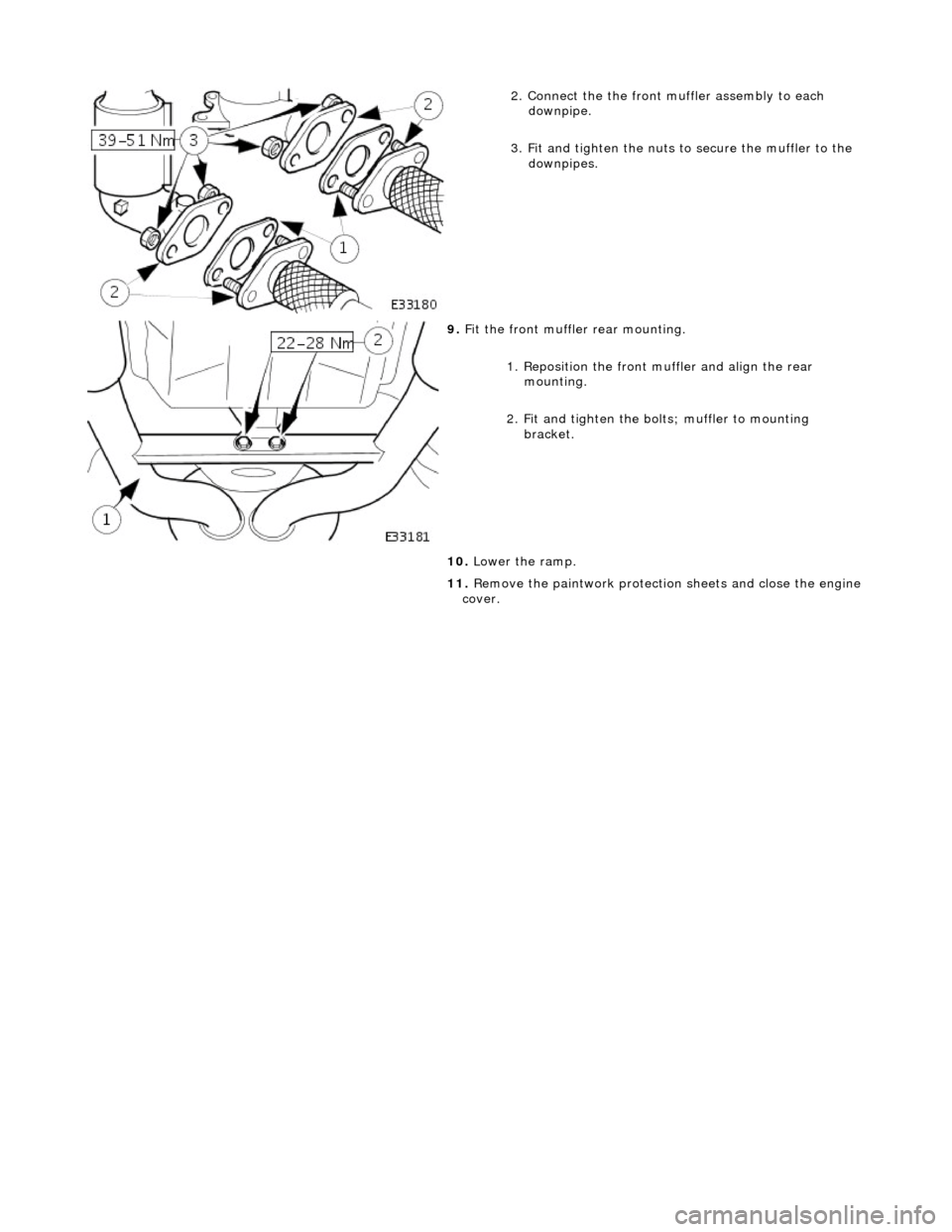
2
. Connect the the front mu
ffler assembly to each
downpipe.
3. Fit and tighten the nuts to secure the muffler to the downpipes.
9. F
it the front muffler rear mounting.
1. Reposition the front mu ffler and align the rear
mounting.
2. Fit and tighten the bolts; muffler to mounting bracket.
10. Lower the ramp.
11. Remove the paintwork protection sheets and close the engine
cover.
Page 1688 of 2490
Fuel System - General Inform
ation - Fuel System
Description an
d Operation
The fuel tank is mounted across the vehicle behind the passenger compartment bulkhead.
Fuel is drawn by the fuel pump from the tank and then supplied to the two fuel rails, via a filter.
Fuel injectors are installed in the fuel ra ils on each side of the intake manifold.
The amount of fuel injected into th e engine is controlled by the ECM.
A cross-over pipe connects the two fuel ra ils together at the front of the manifold.
A test valve in the cross-over pipe allo ws the fuel rail to be pressurized and de-pressurized during the servicing and
troubleshooting procedures.
A pressure regulator on the rear of the right fuel rail controls the pressure in the fuel rails.
A return line directs excess fuel from the pressure regulator back to the fuel tank.
Operation and service procedures
The fuel injector
s, rails, pres
sure regulator and, wher e fitted, supercharger are described in greater detail in Section 303-04
together with servicing procedures.
The fuel tank, pump, fuel level senders and fuel lines are similarly covered in Section 310-01.
Page 1689 of 2490
Fuel System - General Information - Fuel System Pre
ssure Check
Gen
eral Procedures
WARNING: Working on the fuel system re sults in fuel and fuel vapor being present in the atmosphere. Fuel vapor is
extremely flammable, hence great care must be taken whilst working on the fuel system. Adhere strictly to the following
precautions:
пЃ¬D
o not smoke in the work area
пЃ¬Di
splay
NO SMOKING signs around the work area
пЃ¬D
isconnect the battery before
working on the fuel system
пЃ¬Av
oid sparks
пЃ¬Make sure sui
table fire ex
tinguishers are at hand
пЃ¬Make sure absor
bent material is at
hand to soak up any spillage
пЃ¬Make sure the work area is
well ventilated
пЃ¬M
ake sure that the gauge is correctly conn
ected, and that all connections are secure BEFORE starting the engine
пЃ¬DO N
OT
disconnect the gauge from the schrader valve while the engine is running
пЃ¬Make su
re the schrader valve reseals once the gauge is disconnected
• NOTE: Depending on the design of the ga uge set, there may be a drain valve and tube. Make sure this valve is closed, and
the drain tube placed in a suitable container BEFORE connecting the gauge to the schrader valve.
1. Make sure the vehi
cle is in
Park for vehicles with automatic
transmission, Neutral for vehicles with manual transmission.
2. Apply the parking brake.
3. Place suitable absorbent material around the schrader valve to
absorb any spillage when connecting the gauge set.
4. Remove the protective cap from the schrader valve.
5. Connect the gauge, using adaptors if required.
6. Remove the absorbent material and dispose of safely.
7. Disconnect and plug the vacuum hose from the pressure
regulator.
8. Start the engine and record the fuel pressure reading.
пЃ¬As a gui
de, the fuel pressu
re should be approximately 3.0
bar (44.1 psi) with the regulator disconnected.
9. With the engine still running, reconnect the vacuum hose to
the pressure regulator an d record the reading.
пЃ¬Th
e pressure should dr
op to approximately 2.6 bar (38
psi) when the vacuum hose is reconnected.
10. Switch off the engine.
11. Place more absorbent material around the schrader valve.
12. Where fitted, open the drain valve and allow the fuel from the
gauge and line to flow into the container to depressurize the
system.
13. Disconnect and remove the gauge set and any adaptors.
14. Clean up any fuel which may have been spilt and remove the
absorbent material. Dispose of safely.
15. Refit and secure the protective cap to the schrader valve.
16. Reconnect the fuel pressure regulator vacuum hose.
17. Start the engine and make sure there are no leaks.
Page 1690 of 2490
Fuel System - General Information - Fuel System Pressure Rele
ase
Gen
e
ral Procedures
S p
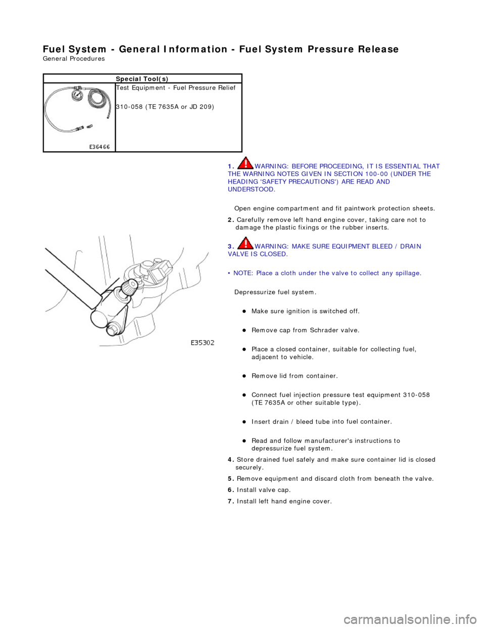
ecial Tool(s)
Tes
t
Equipment - Fuel Pressure Relief
310-058 (TE 7635A or JD 209)
1. WARNING: BEFORE PROCEEDING, IT IS ESSENTIAL THAT
THE WARNING NOTES GIVEN IN SECTION 100-00 (UNDER THE
HEADING 'SAFETY PRECAUTIONS') ARE READ AND
UNDERSTOOD.
Open engine compartment and fi t paintwork protection sheets.
2. Carefull
y remove left
hand engine cover, taking care not to
damage the plasti c fixings or the rubber inserts.
3. WA
RNING: MAKE SURE EQUIPMENT BLEED / DRAIN
VALVE IS CLOSED.
• NOTE: Place a cloth under the valve to collect any spillage.
Depressurize fuel system.
пЃ¬Make sure ignition i s
switched off.
пЃ¬R
e
move cap from Schrader valve.
пЃ¬Pla
c
e a closed container, su
itable for collecting fuel,
adjacent to vehicle.
пЃ¬R e
move lid from container.
пЃ¬Conne
ct
fuel injection pressu
re test equipment 310-058
(TE 7635A or other suitable type).
пЃ¬Insert drain / bleed tu be i
nto fuel container.
пЃ¬R
e
ad and follow manufacturer's instructions to
depressurize fuel system.
4. Store drained f u
el safely and make
sure container lid is closed
securely.
5. Remove equipment and discard cloth from beneath the valve.
6. Install valve cap.
7. Install left hand engine cover.
Page 1691 of 2490
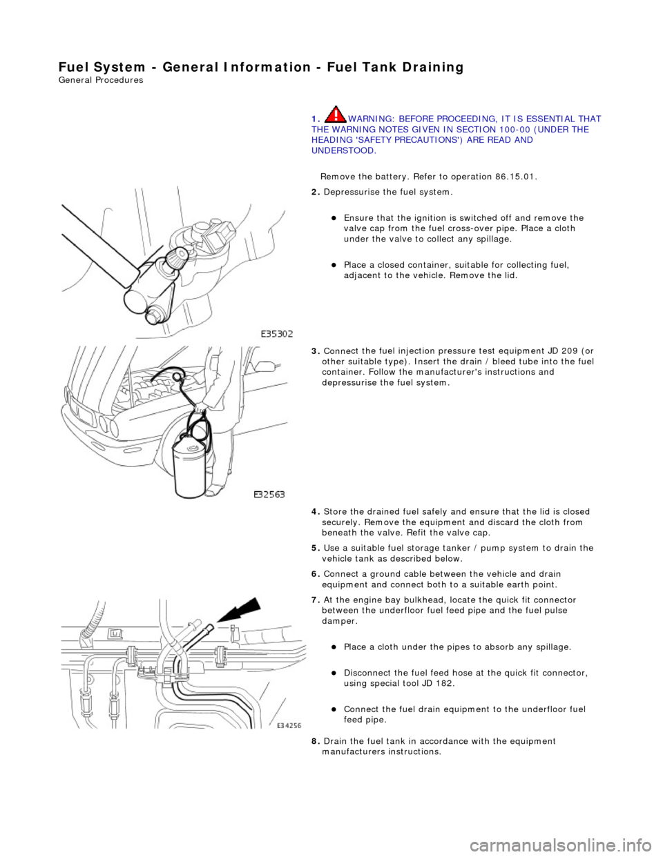
Fuel System - Gener
al Information - Fuel Tank Draining
Gen
eral Procedures
1.
WARNING: BEFORE PROCEEDING, IT IS ESSENTIAL THAT
THE WARNING NOTES GIVEN IN SECTION 100-00 (UNDER THE
HEADING 'SAFETY PRECAUTIONS') ARE READ AND
UNDERSTOOD.
Remove the battery. Refer to operation 86.15.01.
2. De
pressurise the fuel system.
пЃ¬E
nsure that the ignition is
switched off and remove the
valve cap from the fuel cross-over pipe. Place a cloth
under the valve to collect any spillage.
пЃ¬Pla
ce a closed container, su
itable for collecting fuel,
adjacent to the vehicle. Remove the lid.
3. Conne
ct the fuel injection pressu
re test equipment JD 209 (or
other suitable type). Insert the drain / bleed tube into the fuel
container. Follow the manufa cturer's instructions and
depressurise the fuel system.
4. Store the drained fuel safely and ensure that the lid is closed
securely. Remove the equipmen t and discard the cloth from
beneath the valve. Refit the valve cap.
5. Use a suitable fuel storage tank er / pump system to drain the
vehicle tank as described below.
6. Connect a ground cable betw een the vehicle and drain
equipment and connect both to a suitable earth point.
7. At the engine bay bulkhead, lo cate the quick fit connecto
r
between the underfloor fuel feed pipe and the fuel pulse
damper.
пЃ¬Pla
ce a cloth under the pipes
to absorb any spillage.
пЃ¬D
isconnect the fuel feed hose
at the quick fit connector,
using special tool JD 182.
пЃ¬Conne
ct the fuel drain equipment to the underfloor fuel
feed pipe.
8. Drain the fuel tank in accordance with the equipment
manufacturers instructions.
Page 1692 of 2490

Fuel Tank and Lines - Fuel Tank and Li
nes
Description an
d Operation
Fuel Tank
Parts List
The steel fuel tank is located inside the trunk and mounted across the vehicle behind the passenger compartment bulkhead.
The fuel tank is held in posi tion by two retaining straps fi tted to body-mounted brackets.
The fuel tank has an integral non-adjustable fill er pipe and integral breather and vapor pipework.
A single fuel pump is mounted inside the tank on vehicles with normally aspirated engines. For vehicles with supercharged
engines, two pumps are fitted in the tank. Fuel is drawn by the pump(s) from the fuel tank and supplied via the fuel lines
and 70 micron filter to the fuel rails.
The fuel lines run from front-to-rear down the vehicle's left-hand-side.
Ite
m
Part
Number
Descr
iption
1—Fu
el filler latch box
2—Pressure reli
ef pipe, ORVR
(shown) / tank breather pipe on non-ORVR systems
3—Tank grounding
cable
4—Evaporative flan
ge assembly
(ORVR type shown)
5—Trunk elec
trical harne
ss (part of)
6—Fue
l
level sensor
flange/connector
7—Fu
el tank retaining straps
8—F
u
el tank retaining stra
ps adjustable clamps
9—Fu
el tank retaining straps lower brackets
10—Tank vapor outlet pipe to un
derflo
or pipe quick-fit connector
11—F
u
el filler latch bo
x water drain pipe