engine JAGUAR X308 1998 2.G Workshop Manual
[x] Cancel search | Manufacturer: JAGUAR, Model Year: 1998, Model line: X308, Model: JAGUAR X308 1998 2.GPages: 2490, PDF Size: 69.81 MB
Page 1975 of 2490
Location of J1962 socket
The J1962 socket is located at the driver side inboard footwell.
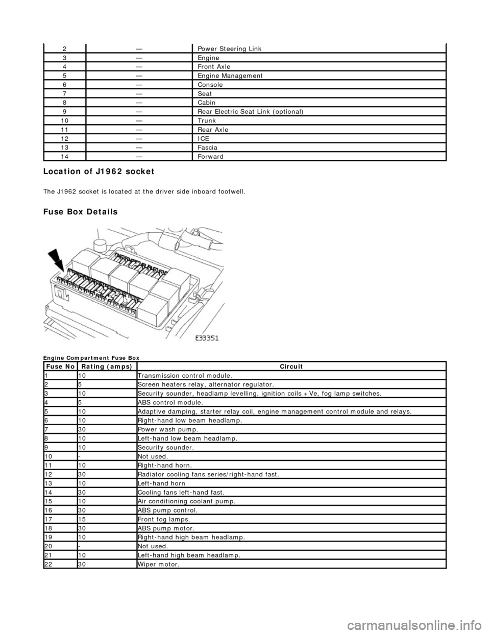
Fuse Box Details
Engine Compartment Fuse Box
2—Power Steering Link
3—Engine
4—Front Axle
5—Engine Management
6—Console
7—Seat
8—Cabin
9—Rear Electric Seat Link (optional)
10—Trunk
11—Rear Axle
12—ICE
13—Fascia
14—Forward
Fuse NoRating (amps)Circuit
110Transmission control module.
25Screen heaters relay, alternator regulator.
310Security sounder, headlamp levelling, ignition coils +Ve, fog lamp switches.
45ABS control module.
510Adaptive damping, starter relay coil, engine management control module and relays.
610Right-hand low beam headlamp.
730Power wash pump.
810Left-hand low beam headlamp.
910Security sounder.
10-Not used.
1110Right-hand horn.
1230Radiator cooling fans series/right-hand fast.
1310Left-hand horn
1430Cooling fans left-hand fast.
1510Air conditioning coolant pump.
1630ABS pump control.
1715Front fog lamps.
1830ABS pump motor.
1910Right-hand high beam headlamp.
20-Not used.
2110Left-hand high beam headlamp.
2230Wiper motor.
Page 1976 of 2490
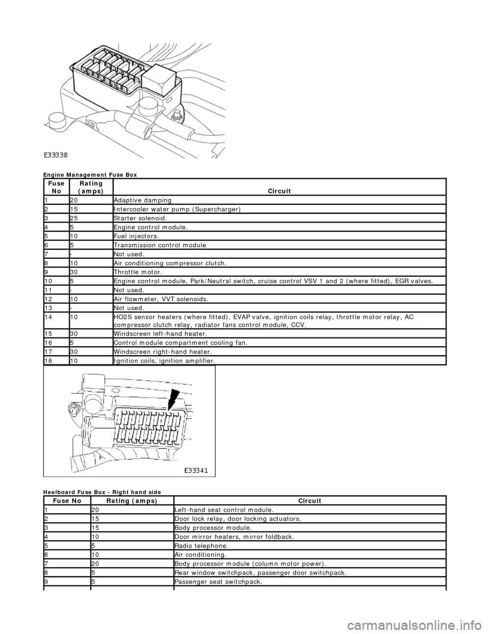
Engine Management Fuse Box
Heelboard Fuse Box - Right hand side
Fuse NoRating
(amps)Circuit
120Adaptive damping
215Intercooler water pump (Supercharger)
325Starter solenoid.
45Engine control module.
510Fuel injectors.
65Transmission control module
7-Not used.
810Air conditioning compressor clutch.
930Throttle motor.
105Engine control module, Park/Neutr al switch, cruise control VSV 1 and 2 (where fitted), EGR valves.
11-Not used.
1210Air flowmeter, VVT solenoids.
13-Not used.
1410HO2S sensor heaters (where fitted ), EVAP valve, ignition coils relay, throttle motor relay, AC
compressor clutch relay, radi ator fans control module, CCV.
1530Windscreen left-hand heater.
165Control module compartment cooling fan.
1730Windscreen right-hand heater.
1810Ignition coils, ignition amplifier.
Fuse NoRating (amps)Circuit
120Left-hand seat control module.
215Door lock relay, door locking actuators.
315Body processor module.
410Door mirror heaters, mirror foldback.
55Radio telephone.
610Air conditioning.
720Body processor module (column motor power).
85Rear window switchpack, passenger door switchpack.
95Passenger seat switchpack.
Page 1978 of 2490
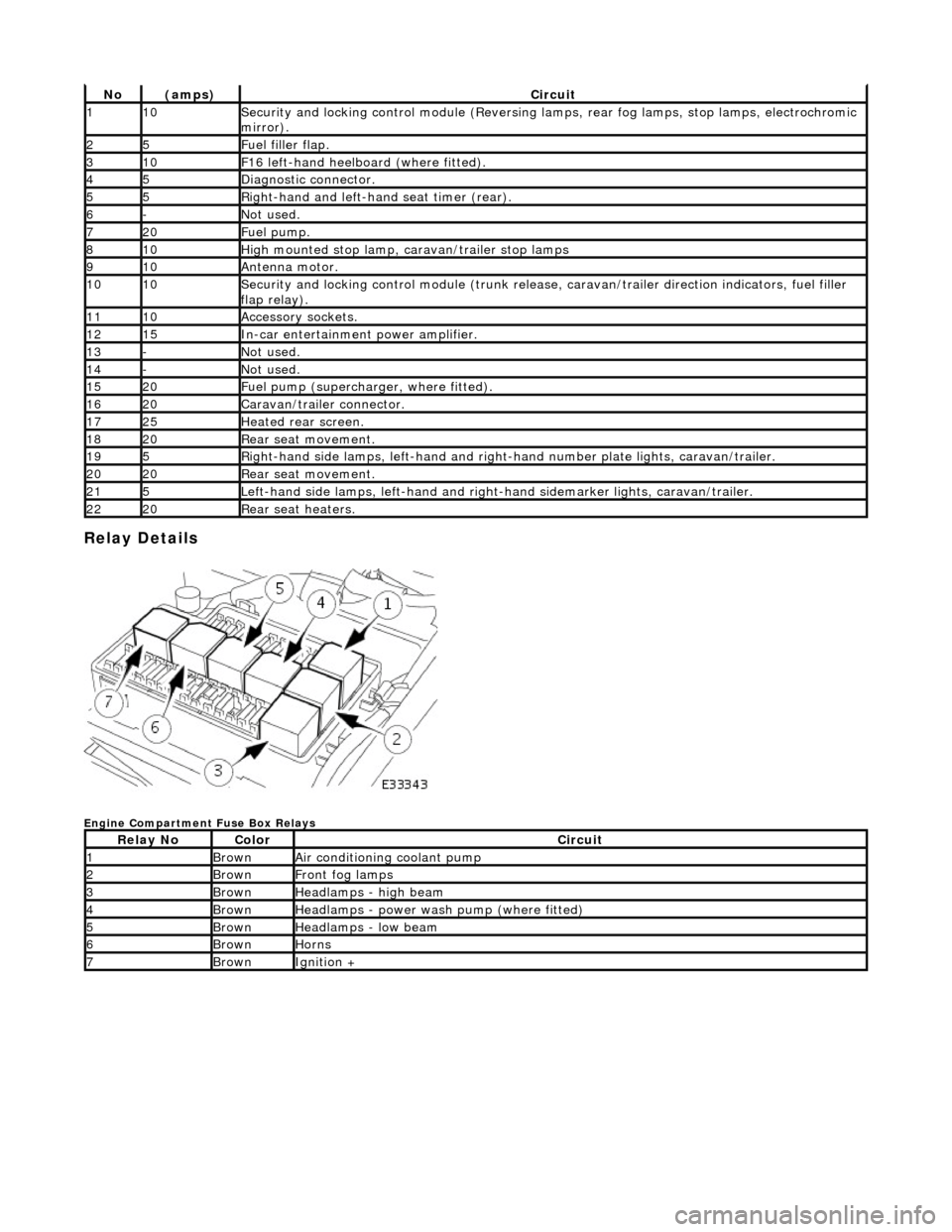
Relay Details
Engine Compartment Fuse Box Relays
No(amps)Circuit
110Security and locking control module (Reversing lamps, rear fog lamps, stop lamps, electrochromic
mirror).
25Fuel filler flap.
310F16 left-hand heelboard (where fitted).
45Diagnostic connector.
55Right-hand and left-han d seat timer (rear).
6-Not used.
720Fuel pump.
810High mounted stop lamp, caravan/trailer stop lamps
910Antenna motor.
1010Security and locking control module (trunk release, caravan/trailer direction indicators, fuel filler
flap relay).
1110Accessory sockets.
1215In-car entertainment power amplifier.
13-Not used.
14-Not used.
1520Fuel pump (supercharger, where fitted).
1620Caravan/trailer connector.
1725Heated rear screen.
1820Rear seat movement.
195Right-hand side lamps, left-h and and right-hand number pl ate lights, caravan/trailer.
2020Rear seat movement.
215Left-hand side lamps, left-hand and right-hand sidemarker lights, caravan/trailer.
2220Rear seat heaters.
Relay NoColorCircuit
1BrownAir conditioning coolant pump
2BrownFront fog lamps
3BrownHeadlamps - high beam
4BrownHeadlamps - power wash pump (where fitted)
5BrownHeadlamps - low beam
6BrownHorns
7BrownIgnition +
Page 1979 of 2490
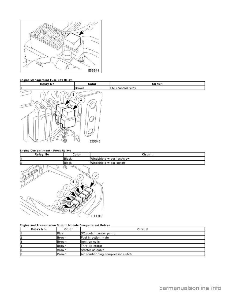
Engine Management Fuse Box Relay
Engine Compartment - Front Relays
Engine and Transmission Control Module Compartment Relays
Relay NoColorCircuit
1BrownEMS control relay
Relay NoColorCircuit
1BlackWindshield wiper fast/slow
2BlackWindshield wiper on/off
Relay NoColorCircuit
1BlueSC coolant water pump
2BrownFuel injection main
3BrownIgnition coils
4BrownThrottle motor
5BrownStarter solenoid
6BrownAir conditioning compressor clutch
Page 2021 of 2490
Body System - General Information - Body
Description and Operation
This section covers the following areas of the vehicle body:
Front end body panels
Body closures
Aperture seals
Door seals
Instrument panel, console and radio
Centre console
Handles, locks, latches and mechanisms
Wipers and washers
Glass, frames and mechanisms
Fascia
Fuel filler flap assembly
Sun visors
Seating
Interior trim and ornamentation
Exterior trim and ornamentation
Rear view mirrors
Rear parcel tray
Roof console
Bumpers
Occupant restraints
Sliding roof
Steering column cowl
Underscuttle pad
Front End Body Panels
A false bulkhead together with two insulation covers, are installed between the engine compartment and the BIW front
bulkhead to provide optimum insulation ag ainst noise and heat intrusion. Two plenum braces bolted between the BIW upper toeboards and the plenum further increase bodyshell structural integrity. The plastic ra diator grill and vane block achieve
weight reductions over steel parts and provid e high resistance to front end corrosion.
Page 2027 of 2490
Front End Body Panels - Front End Body Panels
Description and Operation
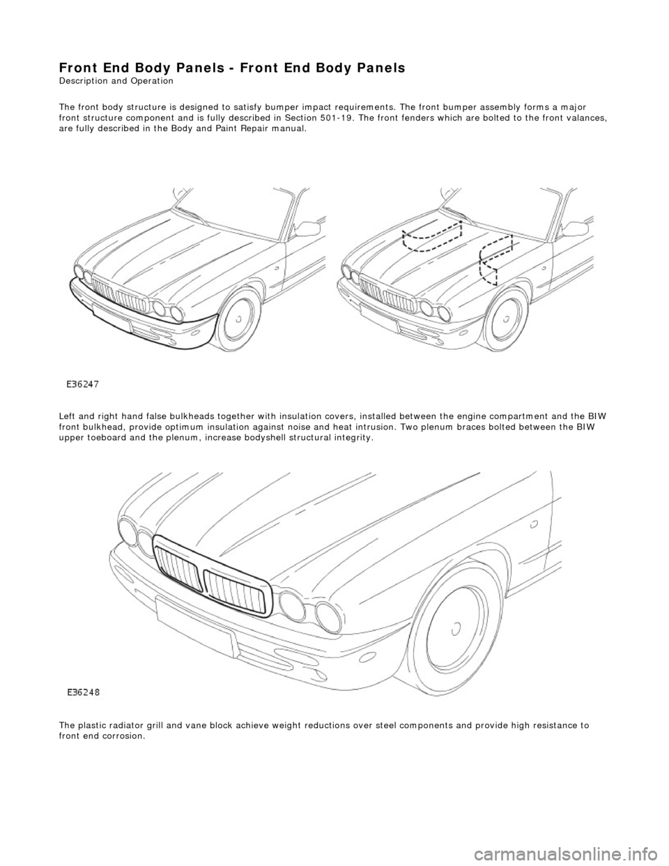
The front body structure is de signed to satisfy bumper impact requiremen ts. The front bumper assembly forms a major
front structure component and is fully desc ribed in Section 501-19. The front fenders which are bolted to the front valances,
are fully described in the Body and Paint Repair manual.
Left and right hand false bulkheads together with insulation covers, installed between the engine compartment and the BIW
front bulkhead, provide optimum insulation against noise and heat intrusion. Two plenum braces bolted between the BIW
upper toeboard and the plenum, increa se bodyshell structural integrity.
The plastic radiator grill and vane block achieve weight reductions over steel components and provide high resistance to
front end corrosion.
Page 2062 of 2490

Interior Trim and Ornamentation - Engine Cover
Removal and Installation
Removal
Installation
1.
Remove the passenger side and dr iver side bulkhead covers.
For additional informat ion, refer to Section 501
-02 Front End Body Panels.
2. Remove the engine cover.
1. To install, reverse the removal procedure.
Page 2099 of 2490
Exterior Trim and Ornamentation - Exterior Trim
Description and Operation
Body Front
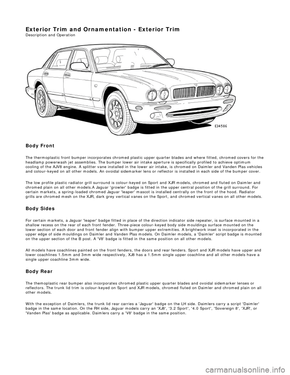
The thermoplastic front bumper incorporates chromed plastic upper quarter blades and where fitted, chromed covers for the headlamp powerwash jet assemblie s. The bumper lower air intake aperture is specifically profiled to achieve optimum
cooling of the AJV8 engine. A splitter vane installed in the lowe r air intake, is chromed on Daimler and Vanden Plas vehicles
and colour-keyed on all other models. An ov oidal sidemarker lens or reflector is installed in each side of the bumper cover.
The low profile plastic radiator grill surround is colour-keyed on Sport and XJR mo dels, chromed and fluted on Daimler and
chromed plain on all other models .A Jaguar 'growler' badge is fitted in the upper central positi on of the grill surround. For
certain markets, a spring-loaded chromed Ja guar 'leaper' mascot is installed centrally on the front of the hood. Radiator
grills are chromed mesh on the XJR, dark grey vertical vanes on the Sport, and chromed ve rtical vanes on all other models.
Body Sides
For certain markets, a Jaguar 'l eaper' badge fitted in place of the direction indicator side re peater, is surface mounted in a
shallow recess on the rear of each fro nt fender. Three-piece colour-keyed body side mouldings surface mounted on the
lower section of each door and front fender align with bumper upper extremities. A brightwork inset is incorporated in the
upper edge of side mouldings on Daimler and Vanden Plas models. On Daimler models, a 'Daimler' script badge is mounted
on the upper section of the B post. A 'V8' badge is fitted in the same position on all other models.
All models have coachlines painted on th e front fenders, the doors and rear fender s. Sport and XJR models have upper and
lower coachlines 1.5mm an d 3mm wide respectively, XJ8 has a 1.5mm single upper coachline and all other models have a
single upper coachline 3mm wide.
Body Rear
The themoplastic rear bumper also inco rporates chromed plastic upper quarter blades and ovoi dal sidemarker lenses or
reflectors. The trunk lid trim is colour-keyed on Sport and XJ R models, chromed fluted on Daimler and chromed plain on all
other models.
With the exception of Daimlers, the trunk lid rear carries a 'Jaguar' badge on the LH side. Daimlers carry a script 'Daimler'
badge in the same location. On th e RH side, Jaguar models carry an 'XJ8', '3.2 Sport', '4.0 Sport', 'Sovereign 8', 'XJR', or
'Vanden Plas' badge as applic able. Daimlers carry a 'V8' badge in the same position.
Page 2245 of 2490

30. Disconnect and remove 'J' gate assembly for access. Refer to
Section 307-05A N/A or 307-05B (S/C).
31. Remove two screws securing facia to air conditioning unit.
32. Remove bolts securing facia to tunnel upper bracket and
bracket to tunnel and remove bracket.
33. On passenger side, release facia harness to passenger
compartment harness multiplug re taining lever and disconnect
multiplug.
34. Remove facia harness to engine management harness
multiplugs (grey and white) fr om 'A' post lower retaining
bracket and disconn ect multiplugs.
Page 2260 of 2490
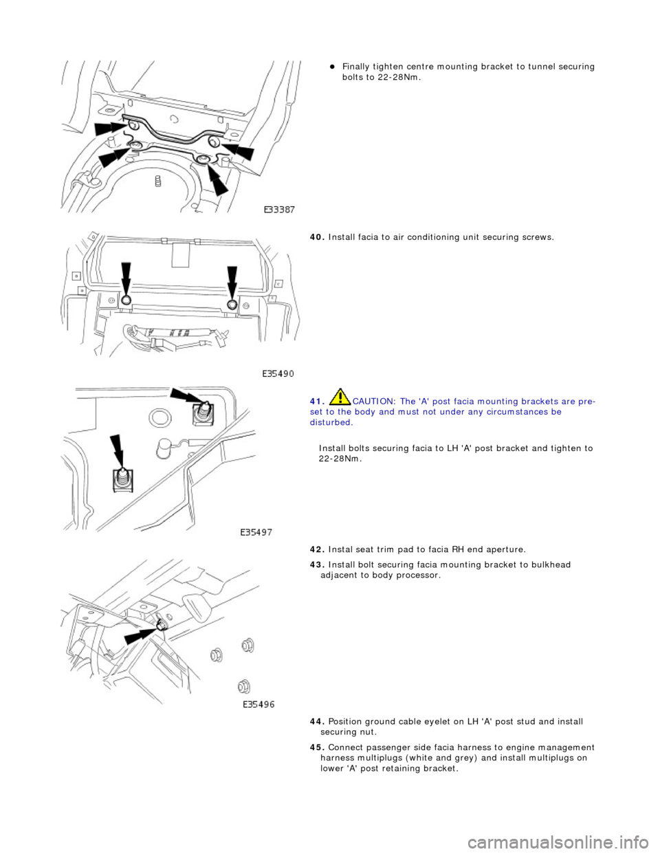
пЃ¬Finally tighten centre mounting bracket to tunnel securing
bolts to 22-28Nm.
40. Install facia to air conditioning unit securing screws.
41. CAUTION: The 'A' post facia mounting brackets are pre-
set to the body and must no t under any circumstances be
disturbed.
Install bolts securing facia to LH 'A' post bracket and tighten to
22-28Nm.
42. Instal seat trim pad to facia RH end aperture.
43. Install bolt securing facia mounting bracket to bulkhead
adjacent to body processor.
44. Position ground cable eyelet on LH 'A' post stud and install
securing nut.
45. Connect passenger side facia harness to engine management
harness multiplugs (white and gr ey) and install multiplugs on
lower 'A' post retaining bracket.