engine JAGUAR X308 1998 2.G Workshop Manual
[x] Cancel search | Manufacturer: JAGUAR, Model Year: 1998, Model line: X308, Model: JAGUAR X308 1998 2.GPages: 2490, PDF Size: 69.81 MB
Page 1823 of 2490
8.8. Automatic
Symbol indicates when the control of , temperature, fan speed and air distribution are all in Auto mode.
9. 9. External
There are two modes of external ambient temperature selection;
пЃ¬Quick Display. Pressing the button for <1.5 seconds (con firmed by a single bleep) will display the external
temperature for 4 seconds.
пЃ¬Continuous Display. Pressing and holding the button fo r >1.5 seconds (confirmed by two beeps) displays the
external ambient temperature continuously, the value of which will be updated every 4 seconds given that vehicle
road speed is > 25 km/h. Pressing the button again fo r <1.5 seconds resets to the previous display.
• NOTE: Continuous external temperature display will be cancel led when the ignition is switched OFF but not during engine
cranking.
10. 10. A/C
This push-on / push-off button will either select or deselect (as indicated by the state lamp) the refrigeration system.
The refrigeration system is automatically engaged when the Auto button is pressed.
• NOTE: Interior misting of screens may be reduced by continuous operation of th e refrigeration system.
11. 11. Auto
When selected and the state lamp lit, A/C mode will be operat ional and control of vent outlet temperature, fans speed and
air distribution will be automatic.
AUTO mode will disengage should manual air distribution or defrost buttons be operated or the manual fan speed knob be
rotated.
• NOTE: Automatic temperature control is constantly main tained irrespective of selected manual overrides.
12. 12. Defrost
Push-on push-off button, which when engaged will direct all air to the front and side glass at maximum fan speed. The
heated windshield (if fitted) will also be energized for a timed cycle of 6,5 minute s, but may be cancelled by pressing the
HEATED WINDSHIELD (F) button. Pressing 'DEF' again will retu rn to the last setting with automatic temperature control
being maintained.
Directing warm and humid air onto a cold screen can produce interior misting of screens. Operating the climate control
system without the refrigerati on system operating will exacerbate this problem.
• NOTE: Directing cold air onto the screen in warm humid conditions can produce external condensation.
13. 13. Heated Windshield (F)
Pressing the heated windshield button (whe re fitted) will energize the electrically heated windshield elements for a timed
cycle of 6,5 minutes; pressing the button again will cancel the request. Should the engine stall or the ignition be turned
OFF, the timer will be cleare d and the function cancelled.
• NOTE: The heated windshield may be activated with the cl imate control system OFF but the engine must be running.
In very cold ambient temperatures, icing of the interior of the glass is possible when the climate control system is operating
in AUTO mode; to reduce this poss ibility the A/CCM provides automatic operation of the heated windshield.
With the following conditions met, the heated windshield will automatically energize but the state lamp will NOT be lit.
Page 1824 of 2490
пЃ¬External temperature < -10 В°C пЃ¬Vehicle speed > 65 km / h пЃ¬The first two conditions exist > 2 minutes. пЃ¬Engine speed > 50 revs / min
14. 14. Heated Backlight (R)
Pressing the heated backlight button will simultaneously energize the heater elements for timed cycles of;
пЃ¬21 minutes backlight пЃ¬11 minutes exterior mirrors
Pressing the button again within the 21 minute timer will cancel the request.
If the engine is stalled, or the ignition switched OFF, the backlight and door mirror timers will be cleared, resulting in both
functions being switched off.
• NOTE: Both the backlight and door mirrors may be activated with the climate control system OFF, but the engine must be
running.
15. 15. Temperature Decrease
Pressing this button (BLUE symbol) decreases the interior temperature setting in 1В° increments. Should the button be
pressed when the setting temperature is below the lower automatic control temperature limit, the display will indicate 'LO'.
16. 16. Temperature Increase
Pressing this button (RED symbol) will raise the temperature setting in 1В° increments Should the button be pressed when
the setting temperature is above the upper automatic control temperature limit, the display will indicate 'HI'.
Automatic Temperature Control Range
В°CВ°F
LOLO
1761
62
1863
64
1965
66
2067
68
2169
70
2271
72
2373
74
2475
76
2577
78
2679
80
2781
82
2883
84
2985
86
3087
88
3189
Page 1828 of 2490
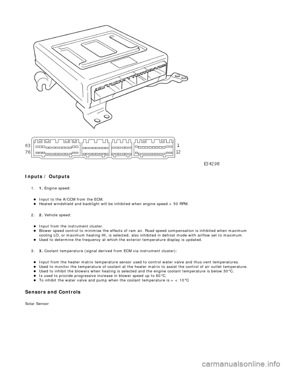
Inputs / Outputs
1.1. Engine speed:
пЃ¬Input to the A/CCM from the ECM. пЃ¬Heated windshield and backli ght will be inhibited when engine speed < 50 RPM.
2. 2. Vehicle speed:
пЃ¬Input from the instru ment cluster. пЃ¬Blower speed control to minimise the effects of ram ai r. Road speed compensation is inhibited when maximum
cooling LO, or maximum heating HI, is selected; also inhi bited in defrost mode with airflow set to maximum.
пЃ¬Used to determine the frequency at which the exterior temperature display is updated.
3. 3. Coolant temperature (signal derived from ECM via instrument cluster):
пЃ¬Input from the heater matrix temperature sensor used to control water valve and thus vent temperatures. пЃ¬Used to monitor the temperature of coolant at the heater matrix to assist the control of air outlet temperature. пЃ¬Used to inhibit the blowers when heating is selected and the engine coolant temperature is below 30В°C. пЃ¬Is used to provide progressive increase in blower speed up to 60В°C. пЃ¬To inhibit the water valve and pump when the coolant temperature is = < 10В°C
Sensors and Controls
Solar Sensor
Page 1831 of 2490
other sensors. This feature prevents the effects of sudden changes in air outlet temperatures due to factors such as:
пЃ¬Recirculating air from the engine cooling pack at low vehicle speeds пЃ¬Sudden changes in ambient temperature пЃ¬The effects of water splash
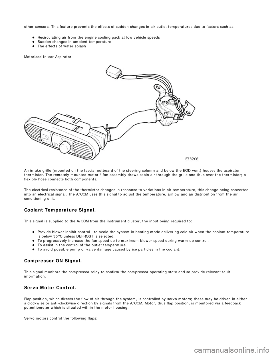
Motorised In-car Aspirator.
An intake grille (mounted on the fascia , outboard of the steering column and below the EOD vent) houses the aspirator
thermister. The remotely mounted motor / fan assembly draws ca bin air through the grille and thus over the thermistor; a
flexible hose connects both components.
The electrical resistance of the thermistor changes in response to variations in air temperatur e, this change being converted
into an electrical signal. The A/CCM uses this signal to adjust the temperature, airflow and air distribution from the air
conditioning unit.
Coolant Temperature Signal.
This signal is supplied to the A/CCM from the instrument cluster, the input being required to:
пЃ¬Provide blower inhibit control , to avoid the system in heat ing mode delivering cold air when the coolant temperature is below 35В°C unless DEFROST is selected. пЃ¬To progressively increase the fan speed up to maximum blower speed during warm up control. пЃ¬To assist in the control of the outlet temperature. пЃ¬To avoid possible pump or valve damage ca used by ice particles in the coolant.
Compressor ON Signal.
This signal monitors the compressor relay to confirm the compressor operating state and so provide relevant fault
information.
Servo Motor Control.
Flap position, which directs the flow of air through the system, is controlled by servo motors; these may be driven in either
a clockwise or anti-clockwise direction by signals from the A/ CCM. Motor, thus flap position, is monitored via a feedback
potentiometer which is situated within the motor housing.
Servo motors control the following flaps:
Page 1832 of 2490
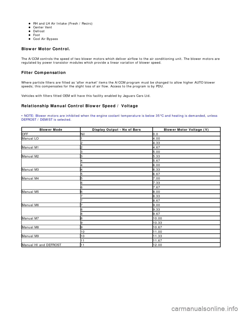
пЃ¬RH and LH Air Intake (Fresh / Recirc) пЃ¬Center Vent пЃ¬Defrost пЃ¬Foot пЃ¬Cool Air Bypass
Blower Motor Control.
The A/CCM controls the speed of two blower motors which deliver airflow to the air conditioning unit. The blower motors are
regulated by power transistor modules which pr ovide a linear variation of blower speed.
Filter Compensation
Where particle filters are fitted as 'after market' items the A/CCM program must be changed to allow higher AUTO blower
speeds; this compensates for the slight loss of air flow. Access to the program is by PDU.
Vehicles with filters fitted OEM will have this facility enabled by Jaguars Cars Ltd.
Relationship Manual Contro l Blower Speed / Voltage
• NOTE: Blower motors are inhibited when the engine coolant temperature is below 35°C and heating is demanded, unless
DEFROST / DEMIST is selected.
Blower ModeDisplay Output - No of BarsBlower Motor Voltage (V)
OFFNil0.0
Manual LO14.00
24.33
Manual M124.67
35.00
Manual M235.33
45.67
46.00
Manual M346.33
56.67
Manual M457.00
67.33
67.67
Manual M568.00
78.33
78.67
Manual M679.00
89.33
89.67
Manual M7810.00
910.33
Manual M8910.67
1011.00
Manual M91011.33
1111.67
Manual HI and DEFROST1112.00
Page 1835 of 2490
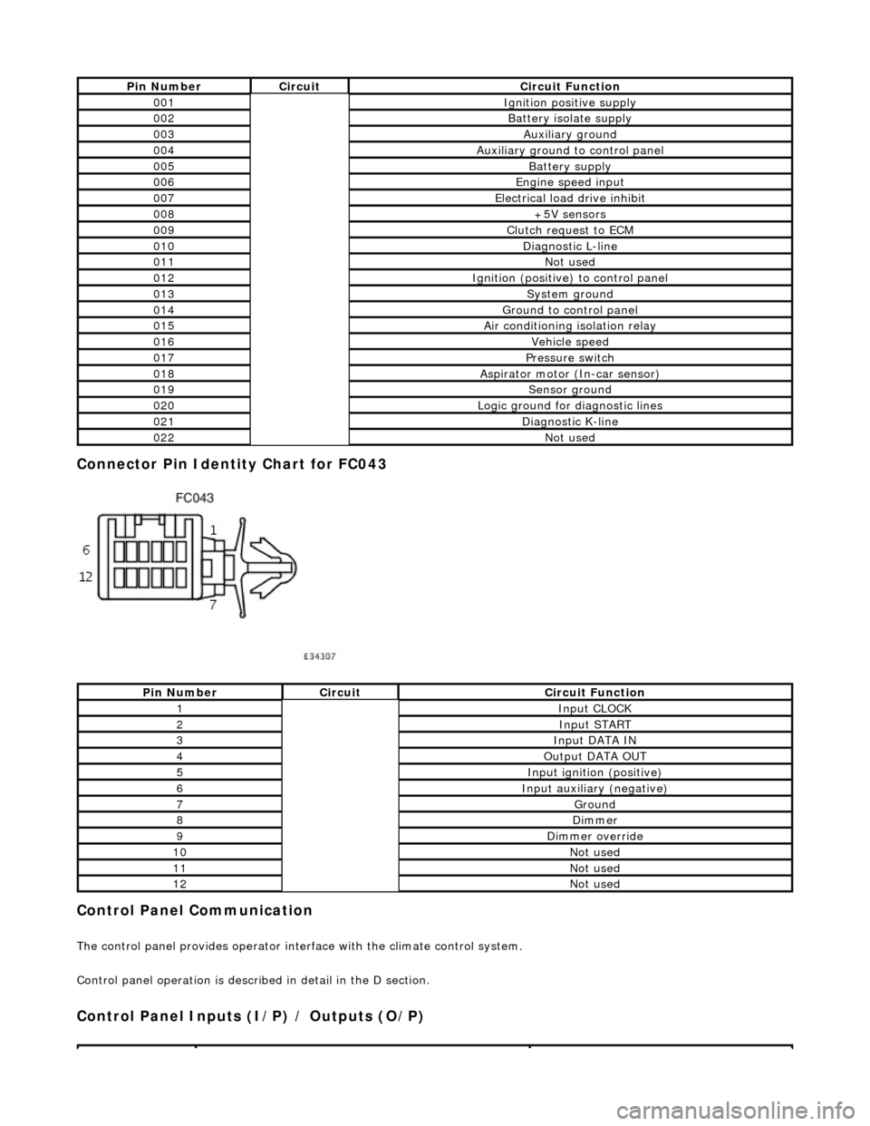
Connector Pin Identity Chart for FC043
Control Panel Communication
The control panel provides operator interface with the climate control system.
Control panel operation is described in detail in the D section.
Control Panel Inputs (I/P) / Outputs (O/P)
Pin NumberCircuitCircuit Function
001Ignition positive supply
002Battery isolate supply
003Auxiliary ground
004Auxiliary ground to control panel
005Battery supply
006Engine speed input
007Electrical load drive inhibit
008+5V sensors
009Clutch request to ECM
010Diagnostic L-line
011Not used
012Ignition (positive) to control panel
013System ground
014Ground to control panel
015Air conditioning isolation relay
016Vehicle speed
017Pressure switch
018Aspirator motor (In-car sensor)
019Sensor ground
020Logic ground for diagnostic lines
021Diagnostic K-line
022Not used
Pin NumberCircuitCircuit Function
1Input CLOCK
2Input START
3Input DATA IN
4Output DATA OUT
5Input ignition (positive)
6Input auxiliary (negative)
7Ground
8Dimmer
9Dimmer override
10Not used
11Not used
12Not used
Page 1837 of 2490
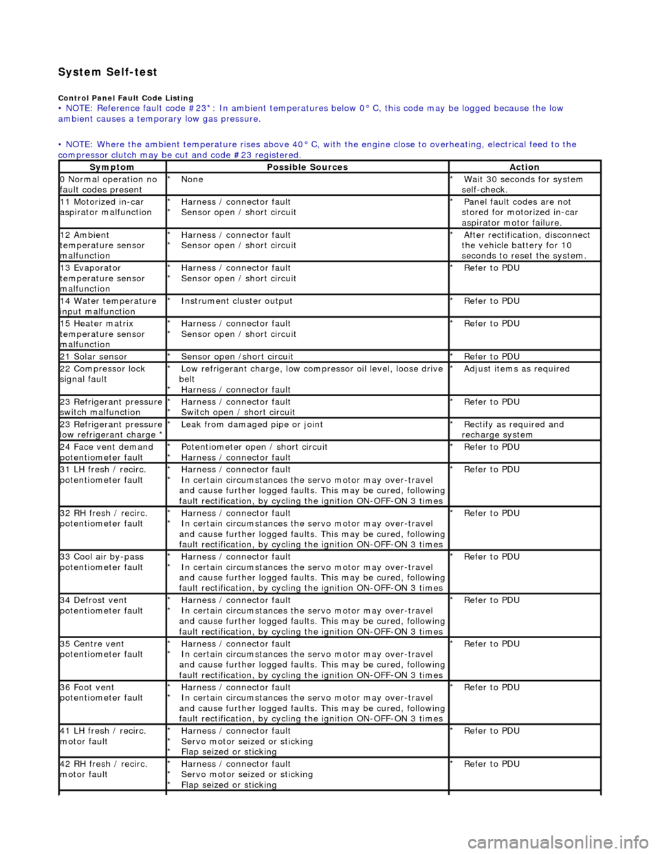
System Self-test
Control Panel Fault Code Listing • NOTE: Reference fault code #23*: In ambient temperatures below 0° C, this code may be logged because the low
ambient causes a tempor ary low gas pressure.
• NOTE: Where the ambient temperature rises above 40° C, with the engine close to overheating, electrical feed to the
compressor clutch may be cut and code #23 registered.
SymptomPossible SourcesAction
0 Normal operation no
fault codes presentNone
*Wait 30 seconds for system
self-check.
*
11 Motorized in-car
aspirator malfunctionHarness / connector fault
Sensor open / short circuit
*
*Panel fault codes are not
stored for motorized in-car
aspirator motor failure.
*
12 Ambient
temperature sensor
malfunctionHarness / connector fault
Sensor open / short circuit
*
*After rectification, disconnect
the vehicle battery for 10
seconds to reset the system.
*
13 Evaporator
temperature sensor
malfunctionHarness / connector fault
Sensor open / short circuit
*
*Refer to PDU
*
14 Water temperature
input malfunctionInstrument cl uster output
*Refer to PDU
*
15 Heater matrix
temperature sensor
malfunctionHarness / connector fault
Sensor open / short circuit
*
*Refer to PDU
*
21 Solar sensorSensor open /short circuit
*Refer to PDU
*
22 Compressor lock
signal faultLow refrigerant charge, low compressor oil level, loose drive
belt Harness / connector fault
*
*Adjust items as required
*
23 Refrigerant pressure
switch malfunctionHarness / connector fault
Switch open / short circuit
*
*Refer to PDU
*
23 Refrigerant pressure
low refrigerant charge * Leak from damaged pipe or joint
*Rectify as required and
recharge system
*
24 Face vent demand
potentiometer faultPotentiometer open / short circuit
Harness / connector fault
*
*Refer to PDU
*
31 LH fresh / recirc.
potentiometer faultHarness / connector fault
In certain circumstances the servo motor may over-travel
and cause further logged faults. This may be cured, following
fault rectification, by cycling the ignition ON-OFF-ON 3 times
*
*Refer to PDU
*
32 RH fresh / recirc.
potentiometer faultHarness / connector fault
In certain circumstances the servo motor may over-travel
and cause further logged faults. This may be cured, following
fault rectification, by cycling the ignition ON-OFF-ON 3 times
*
*Refer to PDU
*
33 Cool air by-pass
potentiometer faultHarness / connector fault
In certain circumstances the servo motor may over-travel
and cause further logged faults. This may be cured, following
fault rectification, by cycling the ignition ON-OFF-ON 3 times
*
*Refer to PDU
*
34 Defrost vent
potentiometer faultHarness / connector fault
In certain circumstances the servo motor may over-travel
and cause further logged faults. This may be cured, following
fault rectification, by cycling the ignition ON-OFF-ON 3 times
*
*Refer to PDU
*
35 Centre vent
potentiometer faultHarness / connector fault
In certain circumstances the servo motor may over-travel
and cause further logged faults. This may be cured, following
fault rectification, by cycling the ignition ON-OFF-ON 3 times
*
*Refer to PDU
*
36 Foot vent
potentiometer faultHarness / connector fault
In certain circumstances the servo motor may over-travel
and cause further logged faults. This may be cured, following
fault rectification, by cycling the ignition ON-OFF-ON 3 times
*
*Refer to PDU
*
41 LH fresh / recirc.
motor faultHarness / connector fault
Servo motor seized or sticking
Flap seized or sticking
*
*
*Refer to PDU
*
42 RH fresh / recirc.
motor faultHarness / connector fault
Servo motor seized or sticking
Flap seized or sticking
*
*
*Refer to PDU
*
Page 1838 of 2490
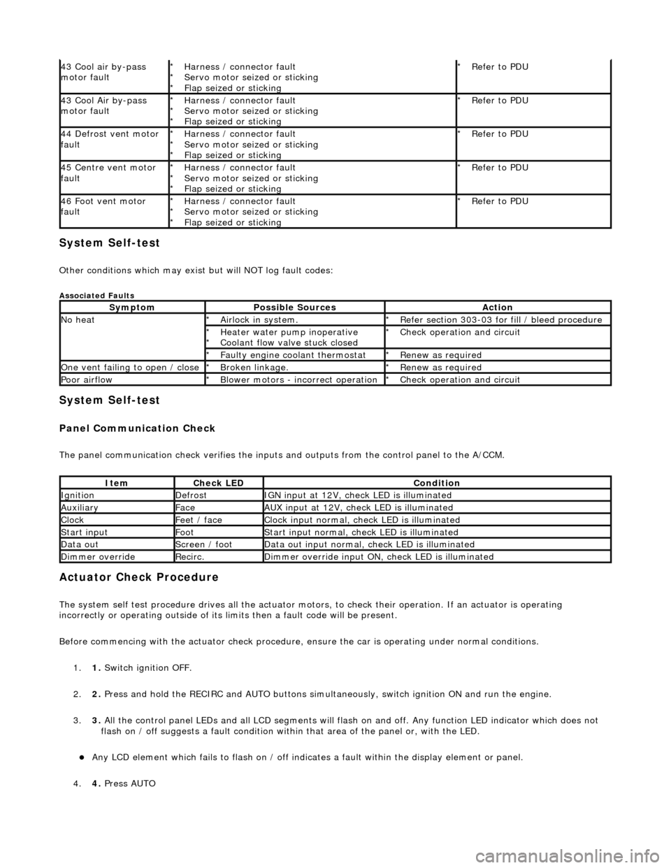
System Self-test
Other conditions which may exist but will NOT log fault codes:
Associated Faults
System Self-test
Panel Communication Check
The panel communication check veri fies the inputs and outputs from the control panel to the A/CCM.
Actuator Check Procedure
The system self test procedure drives all the actuator moto rs, to check their operation. If an actuator is operating
incorrectly or operating outside of its limi ts then a fault code will be present.
Before commencing with the actuator check procedure, ensure the ca r is operating under normal conditions.
1. 1. Switch ignition OFF.
2. 2. Press and hold the RECIRC and AUTO buttons simult aneously, switch ignition ON and run the engine.
3. 3. All the control panel LEDs and all LCD segments will flas h on and off. Any function LED indicator which does not
flash on / off suggests a fault condition within that area of the panel or, with the LED.
пЃ¬Any LCD element which fails to flash on / off indicates a fault within the display element or panel.
4. 4. Press AUTO
43 Cool air by-pass
motor faultHarness / connector fault
Servo motor seized or sticking
Flap seized or sticking
*
*
*Refer to PDU
*
43 Cool Air by-pass
motor faultHarness / connector fault
Servo motor seized or sticking
Flap seized or sticking
*
*
*Refer to PDU
*
44 Defrost vent motor
faultHarness / connector fault
Servo motor seized or sticking
Flap seized or sticking
*
*
*Refer to PDU
*
45 Centre vent motor
faultHarness / connector fault
Servo motor seized or sticking
Flap seized or sticking
*
*
*Refer to PDU
*
46 Foot vent motor
faultHarness / connector fault
Servo motor seized or sticking
Flap seized or sticking
*
*
*Refer to PDU
*
SymptomPossible SourcesAction
No heatAirlock in system.
*Refer section 303-03 for fill / bleed procedure
*
Heater water pump inoperative
Coolant flow valve stuck closed
*
*Check operation and circuit
*
Faulty engine coolant thermostat
*Renew as required
*
One vent failing to open / closeBroken linkage.
*Renew as required
*
Poor airflowBlower motors - incorrect operation
*Check operation and circuit
*
ItemCheck LEDCondition
IgnitionDefrostIGN input at 12V, check LED is illuminated
AuxiliaryFaceAUX input at 12V, check LED is illuminated
ClockFeet / faceClock input normal, check LED is illuminated
Start inputFootStart input normal, check LED is illuminated
Data outScreen / footData out input normal, check LED is illuminated
Dimmer overrideRecirc.Dimmer override input ON, check LED is illuminated
Page 1859 of 2490
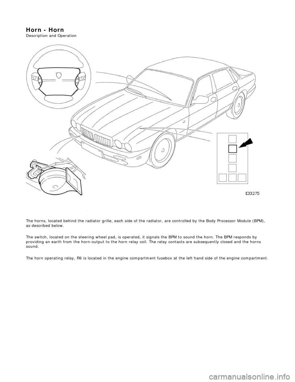
Horn - Horn
Description and Operation
The horns, located behind the radiator gril le, each side of the radiator, are controlled by the Body Processor Module (BPM),
as described below.
The switch, located on the steering wheel pad, is operated, it signals the BPM to sound the horn. The BPM responds by
providing an earth from the horn-output to the horn relay coil. The relay contacts are subsequently closed and the horns
sound.
The horn operating relay, R6 is located in the engine compartm ent fusebox at the left hand side of the engine compartment.
Page 1882 of 2490
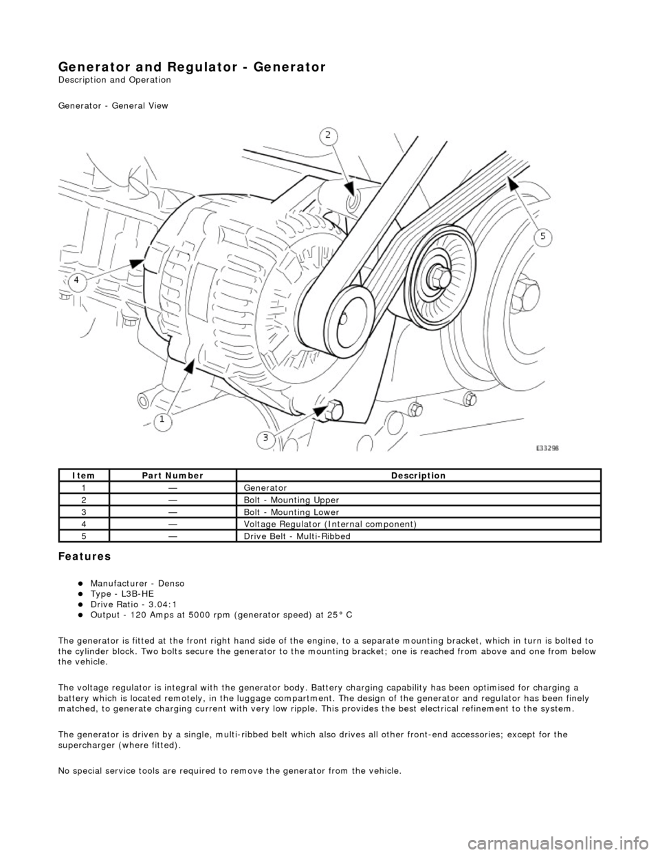
Generator and Regulator - Generator
Description and Operation
Generator - General View
Features
пЃ¬Manufacturer - Denso пЃ¬Type - L3B-HE пЃ¬Drive Ratio - 3.04:1 пЃ¬Output - 120 Amps at 5000 rpm (generator speed) at 25В° C
The generator is fitted at the front right hand side of the engine, to a sepa rate mounting bracket, which in turn is bolted to
the cylinder block. Two bolts secure th e generator to the mounting bracket; one is reached from above and one from below
the vehicle.
The voltage regulator is integral with th e generator body. Battery charging capabi lity has been optimised for charging a
battery which is located remotely, in the luggage compartment. The design of the generator and regulator has been finely
matched, to generate charging current with very low ripple. This provides the best electrical refinement to the system.
The generator is driven by a single, multi-ribbed belt which also drives all other front-e nd accessories; except for the
supercharger (where fitted).
No special service tools are required to remove the generator from the vehicle.
ItemPart NumberDescription
1—Generator
2—Bolt - Mounting Upper
3—Bolt - Mounting Lower
4—Voltage Regulator (Internal component)
5—Drive Belt - Multi-Ribbed