engine JAGUAR X308 1998 2.G Manual PDF
[x] Cancel search | Manufacturer: JAGUAR, Model Year: 1998, Model line: X308, Model: JAGUAR X308 1998 2.GPages: 2490, PDF Size: 69.81 MB
Page 445 of 2490
Anti-Lock Control - Hydraulic Contro
l Unit (HCU)
Re
moval and Installation
Remov
al
• C
AUTIONS:
Replacement of nuts and bolts: Various thread-locking de vices are used on nuts and bolts throughout the vehicle.
These devices restrict the number of times a nut or bolt can be used. See section 100-00 for information.
Remove brake fluid spilla ge immediately from paint work, with clean water.
S
pecial Tool(s)
Brake Pedal
Hold Tool
JDS 9013
1. Disc
onnect battery ground cable (IMPORTANT, see operation
86.15.19 for further information).
2. Position vehicle on a four-post lift.
3. Open engine compartment and fit paint work protection covers
to fenders.
4. NOTE
: The following three pictorial procedures must be
carried-out to minimize brake fl uid loss when disconnecting the
brake tubes.
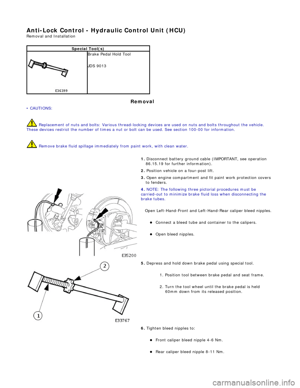
Open Left-Hand-Front and Left-H and-Rear caliper bleed nipples.
пЃ¬Connect
a bleed tube and co
ntainer to the calipers.
пЃ¬O
pen bleed nipples.
5. Depress and hold down brake pedal u
sing special tool.
1. Position tool between brake pedal and seat frame.
2. Turn the tool wheel unti l the brake pedal is held
60mm down from its released position.
6. Tighten bleed nipples to:
пЃ¬Front caliper blee d nipple 4-6
Nm.
пЃ¬Rear
caliper bleed nipple 8-11 Nm.
Page 450 of 2490

Anti-Lock Control - Wheel Speed Se
nsor Ring
Re
mo
val and Installation
Remov
a
l
CAUTI
O
N: Replacement of
nuts and bolts: Various thread-locking devices are used on nuts and bolts throughout the
vehicle. These devices restrict the number of times a nut or bolt can be used. See section 100-00 for information.
S p
ecial Tool(s)
Hub Holdin
g Tool
2
04-195 (JD 227)
ABS Rotor Nut Socket
2
06-
066A
1.
Op
en engine compartment and
fit paintwork protectors to
fenders.
2. Raise front of vehicle and support on stands. Refer to section
100-02.
3. Remove front wheel. Re fer to section 204-04.
4. Remove front brake disc. Refer to operation 70.10.12.
5. Remove vertical link and hub assembly. Refer to operation
60.25.38.90.
6. Re
move brake-disc shield from vertical link.
1. Remove screws.
2. Remove disc shield.
7. Using special tool, secure vertical link and hub assembly in a
vice.
пЃ¬Secure special tool
in a vice.
пЃ¬Posit
i
on hub in tool.
пЃ¬Fit and
tighten wheel nuts.
Page 457 of 2490
•
NOTE: The following steps must be carried out with assistance.
1. 1. With the wheels in the straight ahead po sition, gently turn the steering wheel to the left and the right to check for
free play.
2. 2. Free play should be between 0 and 6 mm (0 and 0.24 in) at the steering wheel rim. If the free play exceeds this
limit, either the ball joints are worn, the lower steering column joints are worn or the backlash of the steering gear
is excessive.
CAUTION: DO NOT attempt to adjust the stee ring gear yoke. Failure to follow this instruction will result in the steering
gear warranty to become invalid.
3. 3. The backlash of the steering gear cannot be adjusted, in stall a new steering gear. For additional information,
REFER to Section 211
-0
2 Power Steering
.
4. 4. Grasp the steering wheel
firm
ly and move it up and down and to the left and right without turning the wheel to
check for column bearing wear, steering wheel or steering column. For additional information,
REFER to Section 211
-0
4 Steering Column
.
Power Steering Fluid Condition Check
1.
1. R
un the engine for 2 minutes.
2. 2. Check the power steering fluid system level.
3. 3. Observe the color and the odor. The color under normal circumstances should be dark reddish, not brown or
black.
4. 4. Allow the fluid to drip onto a faci al tissue and examine the stain.
5. 5. If evidence of solid material is foun d, the power steering fluid system should be drained for further inspection.
6. 6. If fluid contamination or steering co mponent failure is confirmed by the se diment in the power steering fluid
system, REFER to Steering Fault Diagnosis by Symptom Charts in this section.
Power Steer
ing Pressure Test
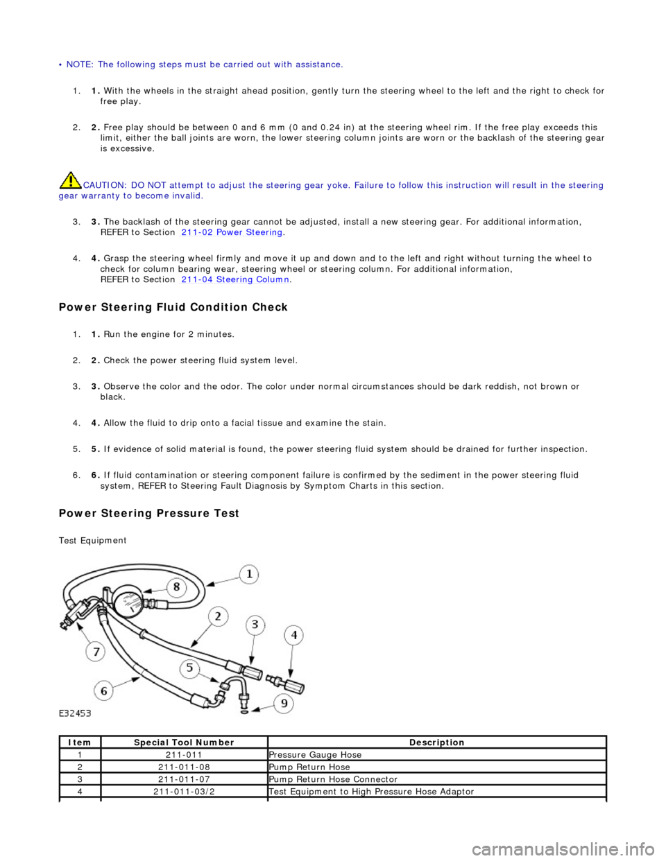
Test Equ
ipment
It
em
S
pecial Tool Number
De
scription
12
11-011
Pres
sure Gauge Hose
221
1-011-08
Pump Return Hose
321
1-011-07
Pump Return Hose Connector
42
11-011-03/2
Test Equ
ipment to High
Pressure Hose Adaptor
Page 458 of 2490
The
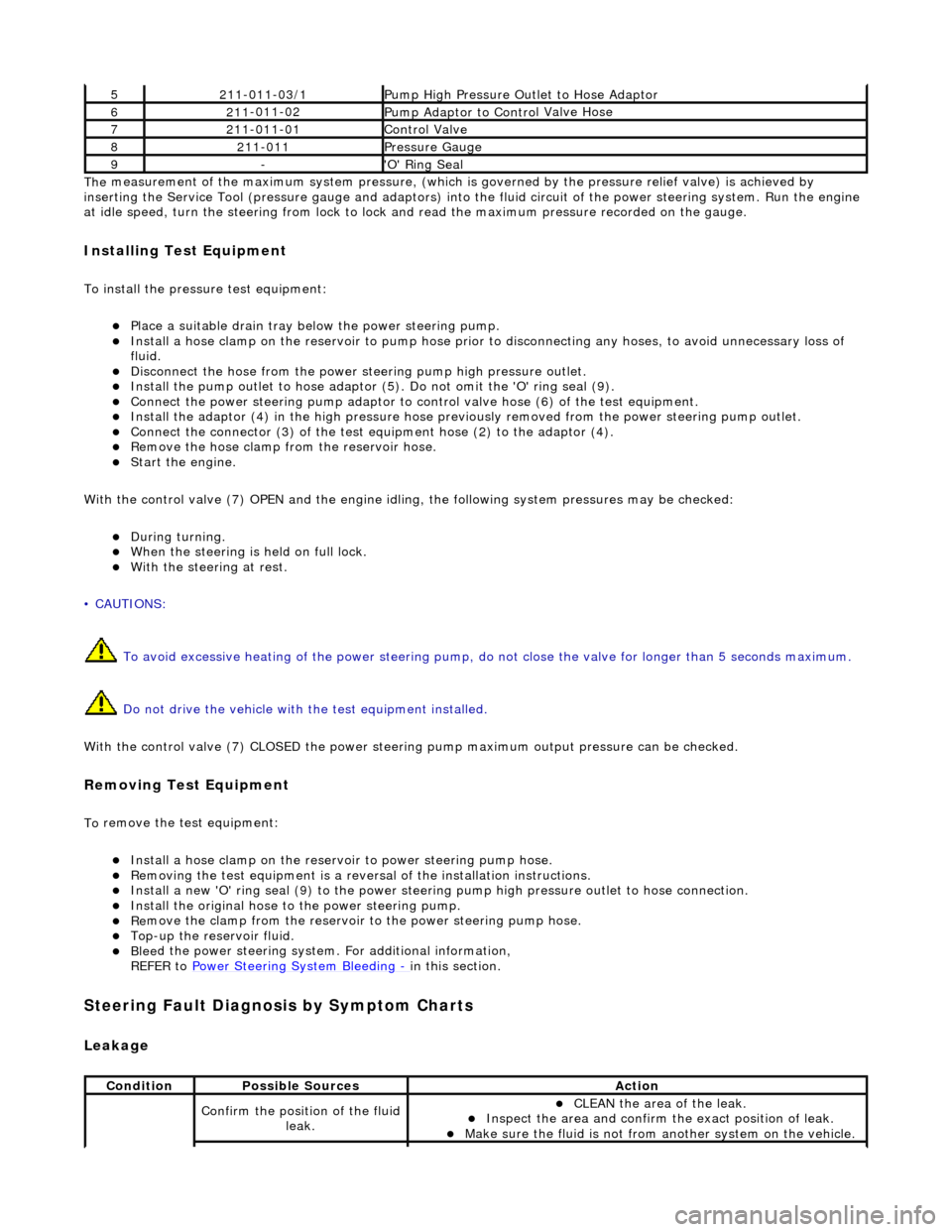
measurement of the maximum system pressure, (which is
governed by the pressure relief valve) is achieved by
inserting the Service Tool (pressure gauge and adaptors) into th e fluid circuit of the power steering system. Run the engine
at idle speed, turn the st eering from lock to lock and read the ma ximum pressure recorded on the gauge.
Installin
g Test Equipment
To
in
stall the pressure test equipment:
пЃ¬Pla
c
e a suitable drain tray be
low the power steering pump.
пЃ¬Install a hose clamp on
the re
servoir to pump hose prior to disconnecting any hoses, to avoid unnecessary loss of
fluid.
пЃ¬Disc
onnect the hose from the power st
eering pump high pressure outlet.
пЃ¬Install the pu
mp outlet to hose adaptor (5
). Do not omit the 'O' ring seal (9).
пЃ¬Connect the power steering
pump
adaptor to control valve hose (6) of the test equipment.
пЃ¬Install th e adaptor (4) in th
e high
pressure hose previously removed from the power steering pump outlet.
пЃ¬Conn
ect the connector (3) of the test equipment hose (2) to the adaptor (4).
пЃ¬R
e
move the hose clamp fro
m the reservoir hose.
пЃ¬Start th
e engine.
With the control valve (7) OPEN and the engine idli ng, the following system pressures may be checked:
пЃ¬Du
ring turning.
пЃ¬W
h
en the steering is
held on full lock.
пЃ¬With
the steeri
ng at rest.
• CAUTIONS:
To avoid excessive heating of the po wer steering pump, do not close the valve for longer than 5 seconds maximum.
Do not drive the vehicle with the test equipment installed.
With the control valve (7) CLOSED the power steering pump maximum ou tput pressure can be checked.
Removing Test Equipment
To
remove the test equipment:
пЃ¬Install a hose clamp
on
the reservoir to power steering pump hose.
пЃ¬Re
movi
ng the test equipmen
t is a reversal of the in stallation instructions.
пЃ¬Install a new '
O
' ring seal (9) to the power steering pump high pressu
re outlet to hose connection.
пЃ¬Instal
l the original hose to
the power steering pump.
пЃ¬Re
move the clamp from the reservoir to
the power steering pump hose.
пЃ¬Top-up the reservoir flui
d.
пЃ¬Ble
e
d the power steerin
g system. For additional information,
REFER to Power Steering System Bleeding
- in thi
s section.
Stee
ring Fault Diagnosis by Sympt
om Charts
Leakage
52
11-0
11-03/1
Pump High Pressure Ou
tlet
to Hose Adaptor
621
1
-011-02
Pump Adaptor
to Contro
l Valve Hose
721
1
-011-01
Control Valve
82
11-
011
Pressure Gauge
9-'O
'
Ring Seal
Cond
iti
on
Possib
l
e Sources
Acti
o
n
Co
nfirm
the position of the fluid
leak.
пЃ¬CLEAN th
e area of the leak.
пЃ¬In
s
pect the area and confirm the exact position of leak.
пЃ¬Make sure the fluid
is not from anoth
er system on
the vehicle.
Page 460 of 2490
пЃ¬Vehicl
e wanders from side to
side on the road, when the vehicle is driven straight ahead and the steering wheel is held in a firm position
пЃ¬Incorrect ti re
pressure or
tire size.
пЃ¬CHECK and ADJ
UST the tire pressure. For
additional information,
REFER to Section 204
-0 4
Wheels and Tires
. пЃ¬IN
ST
ALL a new tire as necessary. For
additional information,
REFER to Section 204
-0 4
Wheels and Tires
.
пЃ¬Vehi
cl
e is unevenly or
excessively loaded.
пЃ¬A D
JUST the load evenly.
пЃ¬Loose/worn ti
e-
rods.
пЃ¬INST
ALL a ne
w tie-rod
end. For additional
information,
REFER to Section 211
-0 3
Steering Linkage
.
пЃ¬Steeri
ng gear bolts loose
o
r damaged.
пЃ¬TIGHTE
N or INSTALL
new bolts.
пЃ¬Loose or worn suspensi
on
ball jo
int(s).
пЃ¬INST
ALL a ne
w suspension ball joint
assembly. For additional information,
REFER to Section 204
-01 Fron
t Suspension
.
пЃ¬Steeri
ng column uni
versal
joint pinch bolt loose.
пЃ¬TI G
HTEN the steering column universal joint
pinch bolt. For additi onal information,
REFER to Section 211
-0 4
Steering Column
.
пЃ¬Incorre
ct
toe adjustment.
пЃ¬ADJUS
T as necessary. For additional
information,
REFER to Section 204
-00 Sus
pension
Sy
ste
m
- General
Information
.
пЃ¬Loose or worn rear
susp
ension.
пЃ¬TIGHTEN
loose, or IN
STALL new rear
suspension components. For additional information,
REFER to Section 204
-0 2
Rear Suspension
.
пЃ¬Vehicle t
e
nds to pull to one
side when driven on a level surface
пЃ¬Incorrect ti
re pressure.
пЃ¬Incorrect
ti
re size or
different tire/tread type.
пЃ¬Uneven tire wear
пЃ¬CHECK and ADJ
UST the tire pressure. For
additional information,
REFER to Section 204
-0 4
Wheels and Tires
. пЃ¬IN
ST
ALL a new tire as necessary. For
additional information,
REFER to Section 204
-04
Wheels and Tires
.
пЃ¬Vehicl
e is unevenly loaded
or overloaded.
пЃ¬Adjust the load
.
пЃ¬Incorre
ct
toe adjustment.
пЃ¬ADJUS
T as necessary. For additional
information,
REFER to Section 204
-00 Sus
pension
Sy
ste
m
- General
Information
.
пЃ¬Dam
a
ged front suspension
components.
пЃ¬I N
STALL new front suspension components
as necessary. For addi tional information,
REFER to Section 204
-01 Fron
t Suspension
.
пЃ¬Damaged rear
suspen
sion
components.
пЃ¬INST ALL ne
w rear suspension components
as necessary. For addi tional information,
REFER to Section 204
-0 2
Rear Suspension
.
пЃ¬Steeri
ng gear val
ve effort
out of balance.
пЃ¬SHIF T the
transmission into NEUTRAL while
driving at no more than 30 miles/hour (50 km/h) and turn the ignition to position I
(engine OFF-coasting). If the vehicle does
not pull with the engine off, INSTALL a new steering gear. For additional information,
REF E
R to Section 211
-0
2
Power Steering
. пЃ¬If t
he
vehicle does drift with the engine off,
CROSS SWITCH front wheel assemblies.
пЃ¬If the
vehicle pulls to
the opposite side,
SWITCH wheels that were on the rear to the
same side on the front.
пЃ¬If the v
ehicle pull dire
ction is not changed,
CHECK the front susp ension components
and toe adjustments. For additional information,
REFER to Section 204
-01 Fron
t Suspension
.
пЃ¬Chec
k
the front and rear
brakes for correct operation.
пЃ¬ADJUS
T as necessary. For additional
information,
REFER to Section 206
-0 0
Brake System
-
General Informati on.
пЃ¬Check fo
r bent rear
пЃ¬INST
ALL ne
w rear suspension components
Page 468 of 2490
Hiss (Swish)
Hiss or Val
ve Hiss is a high-frequency so
und coming from the steering gear when the system is loaded. It is a rushing or
"swish" noise that doesn't change frequency with RPM. Hiss is the general noise generated by the flow of hydraulic fluid
through restrictions in the steer ing system. Restrictions include the rotary stee ring valve, power steering tubes, connectors,
tuning orifices, etc. Hiss can be air- borne and structure-borne, but the structure-borne path through the steering
intermediate shaft is usually dominant.
Moan (Groan)
Moan is the general structu r
e-borne noise of the steering system. Moan is primarily transmitted to the driver via the body
structure through the pump mount, engine mounts, power steering lines and power steering brackets. On some vehicles,
moan is a load humming noise, often present when the wheel is turned and the system is loaded. It may change frequency
with engine RPM and if the sy stem is loaded or unloaded.
Rack Knock (R
ack Slap)
CAU
T
ION: DO NOT attempt to adjust the stee
ring gear yoke. Failure to follow this instruction will result in the steering
gear warranty to become invalid.
Rack Knock is a rattle sound an d steering wheel vibration caused by separation of the steering gear and pinion while driving
over bumps. It is a structure-borne noise transmitted throug h the intermediate shaft and column. Rack knock can also be
heard as a "thump" or impact noise that occurs with the vehicle stationary when the steering wheel is released from a
loaded position and allowed to return to rest . Noise occurs with the engine on or off.
Rattles
Ra
ttles are noises caused by knocking or hitting with components in the steering system. Steering rattles can occur in the
engine compartment, the suspension, or the passenger compartment . Rattles can be caused by loose parts, movable and
flexible parts, and improper clearances.
Squea k
s/Scrapes
Squeaks/Scrapes are noises due
to fri
ction or component rubbi
ng anywhere in the steering system. Squeaks/Scrapes have
appeared in steering linkages and jo ints, in column components and in co lumn and steering wheel trim parts.
Weep
We
ep is an air-borne noise, occasionally
generated when turning the steering across lock at a constant rate. When present
on a vehicle the noise, once initiated can often be maintained across a large proportion of the available steering movement.
Whistle
Wh
istle is similar to hiss but is louder and of a higher frequency. It is also more
of a pure tone noise than hiss. Whistle is
air-borne and is generated by a high flow rate of hydraulic fluid through a small restriction.
Zip
Zip n
o
ise is the air-borne noise
generated by power steerin g pump cavitation when power steering fluid does not flow freely
through the suction hose from the rese rvoir to the pump. Zip primarily occurs during cold weather at start-up.
Steering System Vibrations and Harshne
ss
Buzz
Buzz is a tactile rotary vi
bration felt in
the steering wheel for slow steering inputs. Buzz can also be called a grinding feel
and it is closely related to grunt and is caused by high system gain with low damping. Buzz is generally excited during
parking manoeuvres with low to medium speed steering input.
Page 469 of 2490
Buzz (E
lectrical)
A
different steering buzz can be caused by
pulse width modulated (PWM) electric actuators used in variable assist steering
systems. This buzz is felt by turning the ignition key to run without starting the engine and holding onto the steering wheel.
In extreme cases, the buzz can be felt with the engine running also.
Column/Steering Wheel
Shake
Column shake is a low f
requenc
y vertical vibration excited by primary engine vibrations.
Nibble (Shimm
y)
Steeri
ng nibble is a rotary oscillation or
vibration of the steering wheel, which can be excited at a specific vehicle speed.
Nibble is driven by wheel and tire imbalance exciting a suspensi on recession mode, which then translates into steering gear
travel and finally steering wheel nibble.
Shudder (Judd
er)
Shudder i
s a low frequency oscillation of th
e entire steering system (tire, wheels, st eering gear and linkage, etc.) when the
vehicle is steered during static-park or at low sp eeds. Shudder is very dependent on road surface.
Torque Ri
pple
Torque rippl
e is a concern with Electric Power Steering (EPS) sy
stems. Torque ripple is most evident at static-park steering
the wheel very slowly from lock to lock. Torque ripple is primarily caused by motor commutation.
Torque/Veloc
ity Variation
(Phasing/Effort Cycling)
Steeri
ng wheel torque variation oc
curring twice in one revolution is normally as a result of problems with the lower steering
column (intermediate shaft), but foul cond itions generally result in either constant stiffnes s or single point stiffness.
Depending upon the orientation of the joints, the steering can fe el asymmetric (torque falling off in one direction and rising
in the other) or else it can simply have pronounced peaks and troughs as the steering moves from lock to lock.
Wheel Fight
(Kick Back)
W
heel fight is excess feedback of sudden road forces through th
e steering system and back to the driver. It is evaluated at
all vehicle speeds over cobblestones, rough roads, and potholes . The tires, wheels, and suspension generate forces into the
steering systems. Steering friction, hydraulic damping, hydr aulic compliance, mechanical compliance, steering ratio, and
assist gain all affect how much is transmitted to the driver.
Stee
ring Linkage
CAUTI
ON: Steering gear boots must be
handled carefully to avoid damage. Use new clamps when installing steering
gear boots.
Inspect the boots for cuts, deterioration, tw isting or distortion. Check the steering gear boots to make sure they are tight.
Install new boots or clamps as necessary.
• NOTE: The following steps must be carried out with assistance.
1. 1. With the wheels in the straight ahead po sition, gently turn the steering wheel to the left and the right to check for
free play.
2. 2. Free play should be between 0 and 6 mm (0 and 0.24 in) at the steering wheel rim. If the free play exceeds this
limit, either the ball joints are worn, the lower steering column joints are worn or the backlash of the steering gear
is excessive.
Page 471 of 2490
Stee
ring System - General Informatio
n - Power Steering System Filling
and Bleeding
Gen
eral Procedures
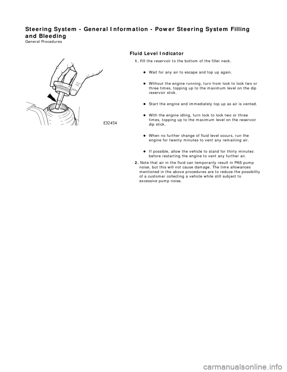
Fluid Level Indica
tor
1.
F
ill the reservoir to the bo
ttom of the filler neck.
пЃ¬W
ait for any air to escape and top up again.
пЃ¬W
ithout the engine running, tu
rn from lock to lock two or
three times, topping up to the maximum level on the dip
reservoir stick.
пЃ¬St
art the engine and
immediately top up as air is vented.
пЃ¬W
ith the engine idling, turn
lock to lock two or three
times, topping up to the ma ximum level on the reservoir
dip stick.
пЃ¬W
hen no further change of
fluid level occurs, run the
engine for twenty minutes to vent any remaining air.
пЃ¬If po
ssible, allow the vehicle
to stand for thirty minutes
before restarting the engine to vent any further air.
2. Note that air in the fluid can temporarily result in PAS pump
noise, but this will not cause damage. The time allowances
mentioned in the above procedures are to reduce the possibility
of a customer collecting a vehicle while still subject to
excessive pump noise.
Page 474 of 2490

Do not al
low the power steering fluid level in the power
steering fluid reservoir to fall below the minimum power
steering fluid level. Fa ilure to follow this instruction may result
in damage to the po wer steering system.
Make sure the engine is swit ched off as soon as the full
4 litres of power steering flui d has entered the power steering
fluid reservoir.
Flush the power steering system.
пЃ¬St art
the engine
пЃ¬W
it
h assistance turn the stee
ring slowly lock to lock 3
times at approximately 1 revo lution every 5 seconds.
пЃ¬Continue
to flush the power steering system until 4
litres of power steering fl uid has been added to the
power steering reservoir. This should take
approximately 30 seconds.
10 . CAUTI
ON: Be prepared to
collect escaping fluids.
Remove the suitable funnel.
11 . CAUTI
ON: Be prepared to
collect escaping fluids.
Remove the suitable pipe to th e power steering return hose.
12. CAUTI
ON: Be prepared to
collect escaping fluids.
Page 476 of 2490

Steering System - Gen
eral Informatio
n - Power Steering System Vacuum
Filling and Bleeding
Gen e
ral Procedures
Fluid Ho
ses
1.
Parts L i
st
It
e
m
De
scr
iption
1R
e
turn hose
2High
pressure h
ose
2. If vacuum filling equipment is available, proceed as follows:
пЃ¬Disconnect both the
high pres
sure hose and return hose
from the PAS pump and the re turn hose from the steering
rack.
пЃ¬D rain as much fl
uid as possible from the system by
turning the steering from lock to lock two or three times.
пЃ¬Re conn
ect all hoses.
пЃ¬Fi
ll
the system using the vacuum equipment according to
the manufacturers instructions.
пЃ¬St art
the engine and top up
the fluid as necessary.
пЃ¬Turn the steering from lock to lock two or three ti mes wi
th
the engine running, topping up with fluid as necessary.
пЃ¬If possibl
e, run the engine for twenty minutes to expel any
remaining air.