engine JAGUAR X308 1998 2.G Owner's Guide
[x] Cancel search | Manufacturer: JAGUAR, Model Year: 1998, Model line: X308, Model: JAGUAR X308 1998 2.GPages: 2490, PDF Size: 69.81 MB
Page 320 of 2490

Brake Sys
tem - General Informatio
n - Brake System BleedingVehicles
With: Standard Brakes
Gen e
ral Procedures
WARNING: WASH HANDS AFTER HANDLING BRAKE FLUID. IF BRAKE FLUID COMES INTO CONTACT WITH THE EYES,
FLUSH EYES WITH COLD RUNNING WATER. IF IRRITATION PERSISTS SEEK MEDICAL ATTENTION. IF BRAKE FLUID IS
TAKEN INTERNALLY, DRINK WATER AND INDUCE VO MITING. GET MEDICAL ATTENTION IMMEDIATELY.
CAUTION: Remove brake fluid spillage imme diately from paint work with clean water.
1. Position vehi cl
e on a four-post lift.
2. Open engine compartment and fit paint work protection covers
to fenders.
3. NO
TE: Make sure the
brake-fluid level does not fall below the
fluid reservoir 'MIN' (minimum) mark when bleeding the brake
system.
Fill fluid reservoir to the 'MAX' (maximum) mark.
4. Prepare l e
ft-hand front, br
ake-caliper for bleeding.
пЃ¬Remove du
st cap.
пЃ¬Connect b
l
eed pipe
and fluid container to bleed nipple.
5. Bleed the brake.
1. Apply pressure to brake pedal
2. Open bleed nipple.
3. Fully depres s brake pedal.
4. Close bleed nipple.
5. Release brake pedal.
6. Wait two seconds to allow system to prime.
7. Repeat procedure until air- free brake fluid is expelled
from the caliper.
6. Tighten bleed nipple, see torque settings below.
Page 322 of 2490

Brake Sys
tem - General Informatio
n - Brake System BleedingVehicles
With: High Performance Brakes
Gen e
ral Procedures
1. WARNINGS:
IF BRAKE FLUID IS TAKEN INTERNALLY, DRINK WATER
AND INDUCE VOMITING. GET MEDICAL ATTENTION
IMMEDIATELY.
WASH HANDS AFTER HANDLING BRAKE FLUID. IF BRAKE
FLUID COMES INTO CONTACT WITH THE EYES, FLUSH EYES
WITH COLD RUNNING WATER. IF IRRITATION PERSISTS SEEK
MEDICAL ATTENTION.
CAUTION: Remove brake flui d spillage immediately from
paint work with clean water.
Position vehicle on a four-post lift.
2. Op
en engine compartment and fit
paint work protection covers
to fenders.
3. NO
TE: Make sure the
brake-fluid level does not fall below the
fluid reservoir 'MIN' (minimum) mark when bleeding the brake
system.
Fill fluid reservoir to the 'MAX' (maximum) mark.
4. Pr
epare the left-hand front,
brake-caliper for bleeding.
пЃ¬Connect b
leed pipes an
d fluid containers to bleed nipples.
5. Bleed the brake.
1. Apply pressure to brake pedal.
2. Open caliper's outer bleed nipple.
3. Fully depres s brake pedal.
Page 343 of 2490

Front Disc Brake - Brake CaliperVehicles
With: Standard Brakes
Re
moval and Installation
Remov
al
W
ARNING: BRAKE DUST, IF INHALED CAN DAMAGE YOUR
HEALTH. ALWAYS REMOVE BRAKE DUST USING A VACUUM
BRUSH. DO NOT USE A COMPRESSED-AIR LINE TO DISPERSE BRAKE DUST INTO THE ATMOSPHERE.
• CAUTIONS:
Replacement of nuts and bolts: Various thread-locking de vices are used on nuts and bolts throughout the vehicle.
These devices restrict the number of times a nut or bolt can be used. See section 100-00 for information.
Remove brake fluid spilla ge immediately from paint work, with clean water.
A new brake hose must be installe d when replacing a brake caliper.
The brake pad adhesive backing must not be reused, therefore always install new brake pads, irrespective of the
condition of the original pads when replacing a brake caliper. Always replace brake pads as an axle set.
S
pecial Tool(s)
Brake Pedal
Hold Tool
JDS 9013
1. O
pen engine compartment and fit
paint work protection covers
to fenders.
2. Raise vehicle on a four-post lift.
3. Raise front of vehicle and support on stands. Refer to Section
100-02.
4. Remove front wheels. See Section 204-04.
5. NOTE
: The following three pictorial procedures must be
carried-out to minimize brake fl uid loss when disconnecting the
brake hose.
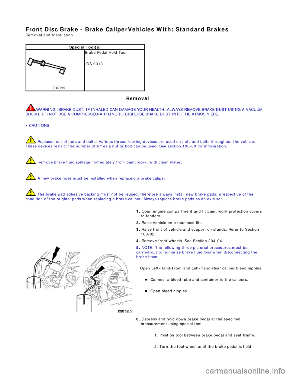
Open Left-Hand-Front and Left-H and-Rear caliper bleed nipples.
пЃ¬Connect
a bleed tube and co
ntainer to the calipers.
пЃ¬O
pen bleed nipples.
6. Depress and hold down brak e pedal at the specified
measurement using special tool.
1. Position tool between brake pedal and seat frame.
2. Turn the tool wheel unti l the brake pedal is held
Page 347 of 2490

Front Disc Brake - Brake CaliperVehicles With: High Performance Brakes
Re
moval and Installation
Remov
al
S
pecial Tool(s)
Brake Pedal
Hold Tool
JDS 9013
1. WARNING: BRAKE DUST, IF INHALED CAN DAMAGE
YOUR HEALTH. ALWAYS REMOVE BRAKE DUST USING A VACUUM
BRUSH. DO NOT USE A COMPRE SSED-AIR LINE TO DISPERSE
BRAKE DUST INTO THE ATMOSPHERE.
• CAUTIONS:
Replacement of nuts and bolts: Various thread-locking
devices are used on nuts and bolts throughout the vehicle. These
devices restrict the number of ti mes a nut or bolt can be used.
See section 100-00 for information.
Remove brake fluid spillage immediately from paint work,
with clean water.
The Brembo caliper is aligned to the brake disc when it is
first installed to the vehicle, therefore, care must be taken not to
disturb this alignment. When removing the caliper; remove the
bolts that secure the anchor bracket to the vertical link only. DO
NOT loosen any other caliper bolts.
Open engine compartment and fit paint work protection covers
to fenders.
2. R
aise vehicle on a four-post lift.
3. Raise front of vehicle and support on stands. Refer to Section
100-02.
4. Remove front wheels. Refe r to operation 74.20.05.
5. NOTE
: The following three pictorial procedures must be
carried-out to minimize brake fl uid loss when disconnecting the
brake hose.
Open Left-Hand-Front and Left-H and-Rear caliper bleed nipples.
пЃ¬Connect
a bleed tube and co
ntainer to the calipers.
пЃ¬O
pen bleed nipples.
6. Depress and hold down brak e pedal at the specified
measurement using the special tool.
Page 351 of 2490

Front Dis
c Brake - Brake DiscVe
hicles With: Standard Brakes
Re
moval and Installation
Remov
al
• WAR
NINGS:
BRAKE DISCS MUST ALWAYS BE REPLACED IN PAIRS.
BRAKE DUST, IF INHALED CAN DAMAGE YOUR HEALTH. ALWAYS REMOVE BRAKE DUST USING A VACUUM BRUSH.
DO NOT USE A COMPRESSED-AIR LINE TO DI SPERSE BRAKE DUST INTO THE ATMOSPHERE.
CAUTION: Replacement of nuts and bolts: Various thread-locking devices are used on nuts and bolts throughout the
vehicle. These devices restrict the number of times a nut or bolt can be used. See section 100-00 for information.
1. O
pen engine compartment and in
stall paint work protection
covers to fenders.
2. Raise front of vehicle and suppo rt on stands. See Section 100-
02.
3. Remove front wheels. Re fer to Section 204-04.
4. CAUTI
ON: Remove brake flui
d spillage immediately from
paint work, with clean water.
Loosen brake fluid reservoir-cap.
пЃ¬Position a cloth around the
reservoir to collect any fluid
spillage.
5. CAU
TION: Tie caliper housing aside. Do not allow the
caliper housing to hang on the hydraulic hose, as this will damage
the hose.
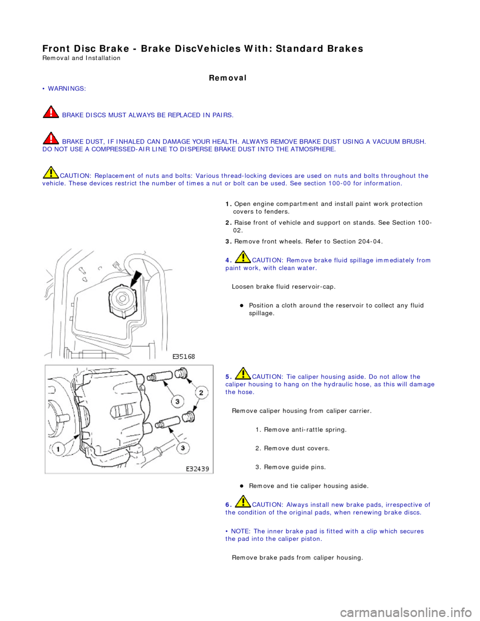
Remove caliper housing from caliper carrier.
1. Remove anti-rattle spring.
2. Remove dust covers.
3. Remove guide pins.
пЃ¬Re
move and tie caliper housing aside.
6.
CAUTI
ON: Always install new brake pads, irrespective of
the condition of the original pads, when renewing brake discs.
• NOTE: The inner brake pad is fitted with a clip which secures
the pad into the caliper piston.
Remove brake pads from caliper housing.
Page 354 of 2490

пЃ¬Remo
ve cloth.
пЃ¬Fit ca
p.
10. Remove paint work protection covers, and close engine
compartment.
11. Start the engine and repeatedly press the brake pedal until
brake pressure is evident.
Page 355 of 2490

Front Dis
c Brake - Brake DiscVehicles With: High Performance Brakes
Re
moval and Installation
Remov
al
1.
WAR
NINGS:
BRAKE DISCS MUST ALWAYS BE REPLACED IN PAIRS.
BRAKE DUST, IF INHALED CAN DAMAGE YOUR HEALTH.
ALWAYS REMOVE BRAKE DUST USING A VACUUM BRUSH. DO
NOT USE A COMPRESSED-AIR LINE TO DISPERSE BRAKE DUST
INTO THE ATMOSPHERE.
• CAUTIONS:
Replacement of nuts and bolts: Various thread-locking
devices are used on nuts and bolts throughout the vehicle. These
devices restrict the number of ti mes a nut or bolt can be used.
See section 100-00 for information.
The Brembo caliper is aligned to the brake disc when it is
first installed to the vehicle, therefore, care must be taken not to
disturb this alignment. When removing the caliper; remove the
bolts that secure the anchor bracket to the vertical link only. DO
NOT loosen any other caliper bolts.
The front brake discs are dire ctional and must be installed
to the correct side of the vehi cle. Refer to Description and
Operation, section 206-03 for further information.
Do not loosen bolts securing brake disc to disc mounting.
Open engine compartment and in stall paint work protection
covers to fenders.
2. R
aise front of vehicle and suppo
rt on stands. See Section 100-
02.
3. Remove front wheels. Refe r to operation 74.20.05.
4. CAUTI
ON: Remove brake flui
d spillage immediately from
paint work, with clean water.
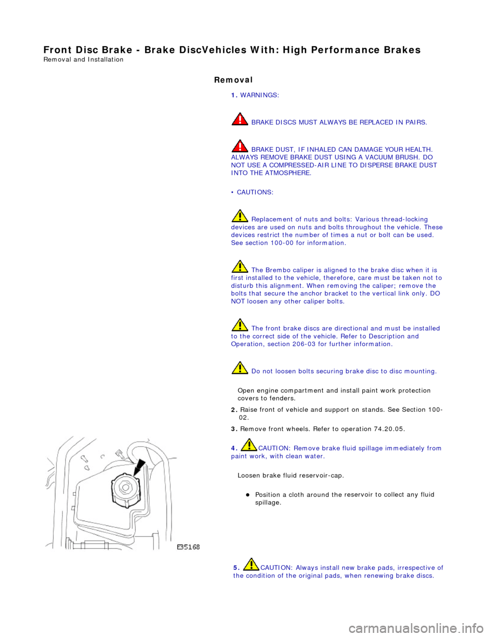
Loosen brake fluid reservoir-cap.
пЃ¬Position a cloth around the
reservoir to collect any fluid
spillage.
5. CAUTI
ON: Always install new brake pads, irrespective of
the condition of the original pads, when renewing brake discs.
Page 358 of 2490

9.
CAUTIO
N: Remove brake flui
d spillage immediately from
paint work, with clean water.
Check brake fluid level.
пЃ¬Check brak e flu
id level is
at the maximum mark.
пЃ¬Remo
ve cloth.
пЃ¬Fi
t ca
p.
10.
R
emove paint work protection
covers, and close engine
compartment.
11. Start the engine and repeatedly press the brake pedal until
brake pressure is evident.
Page 359 of 2490

Front Dis
c Brake - Brake PadsVe
hicles With: Standard Brakes
Re
moval and Installation
Remov
al
W
ARNING: BRAKE DUST, IF INHALED CAN DAMAGE YOUR
HEALTH. ALWAYS REMOVE BRAKE DUST USING A VACUUM
BRUSH. DO NOT USE A COMPRESSED-AIR LINE TO DISPERSE BRAKE DUST INTO THE ATMOSPHERE.
CAUTION: Replacement of nuts and bolts: Various thread-locking devices are used on nuts and bolts throughout the
vehicle. These devices restrict the number of times a nut or bolt can be used. See section 100-00 for information.
1. O
pen engine compartment and fit
paint work protection covers
to fenders.
2. Raise front of vehicle and suppo rt on stands. See Section 100-
02.
3. Remove front wheels. See Section 204-04.
4. CAUTI
ON: Remove brake flui
d spillage immediately from
paint work, with clean water.
Loosen brake fluid reservoir-cap.
пЃ¬Position a cloth around the
reservoir to collect any fluid
spillage.
5. CAU
TION: Tie caliper housing aside. Do not allow the
caliper housing to hang on the hydraulic hose, as this will damage
the hose.
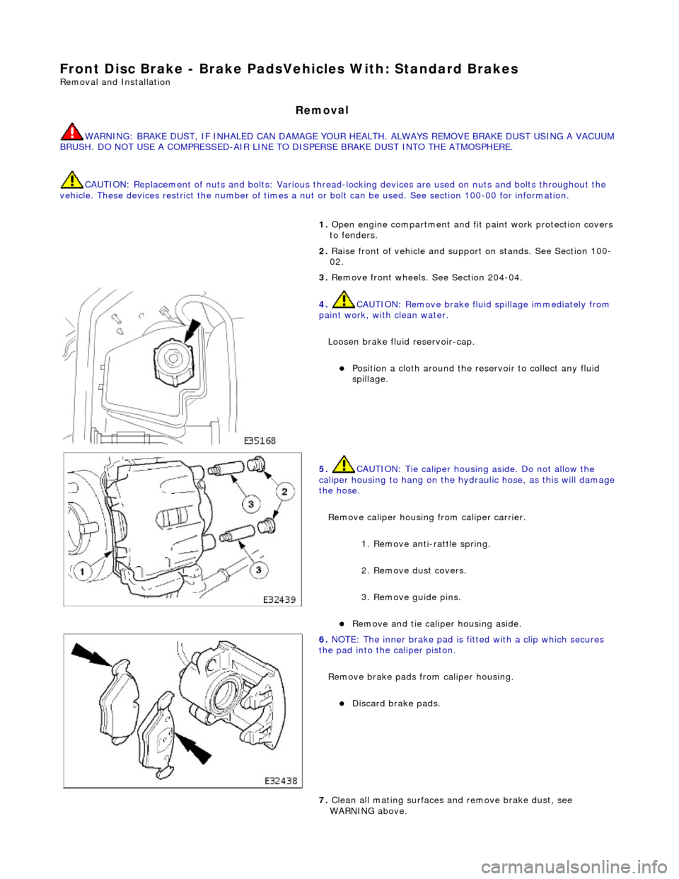
Remove caliper housing from caliper carrier.
1. Remove anti-rattle spring.
2. Remove dust covers.
3. Remove guide pins.
пЃ¬Re
move and tie caliper housing aside.
6.
NO
TE: The inner brake pad is fitt
ed with a clip which secures
the pad into the caliper piston.
Remove brake pads from caliper housing.
пЃ¬Discard
brake pads.
7. Clean all mating surfaces and remove brake dust, see
WARNING above.
Page 360 of 2490

In
stallation
8.
Repeat ab
ove procedure to remo
ve opposite side brake pads.
1. CAUTIO
N: Retracting the caliper piston may cause the
fluid reservoir to over-flow. Remove brake fluid spillage
immediately from paint work, with clean water.
• NOTE: Clean caliper piston to pad mating surface.
Install brake pads in to caliper housing.
1. Slowly retract piston into caliper housing.
2. Remove paper backing from pads to reveal adhesive shim. Install brake pads, insert clip located on back of
inner pad into caliper piston.
2. Instal
l caliper housing to caliper carrier.
пЃ¬Align hou
s
ing to carrier.
1. Install and tighten guide pins to 25-30 Nm.
2. Install dust covers.
3. Install anti-rattle spring.
3. Repeat above procedure to install opposite side brake pads.
4. Fit wheels. Refer to section 204-04.
5. Remove stands and lower vehicl e. Refer to section 100-02.
6. CAUTIO
N: Remove brake flui
d spillage immediately from
paint work, with clean water.
Check brake fluid level.
пЃ¬Check brak e flu
id level is
at the maximum mark.
пЃ¬Remo
ve cloth.
пЃ¬Fi
t ca
p.
7.
Re
move paint work protection
covers, and close engine
compartment.
8. Start the engine and repeatedly press the brake pedal until
brake pressure is evident.