engine JAGUAR X308 1998 2.G Repair Manual
[x] Cancel search | Manufacturer: JAGUAR, Model Year: 1998, Model line: X308, Model: JAGUAR X308 1998 2.GPages: 2490, PDF Size: 69.81 MB
Page 420 of 2490
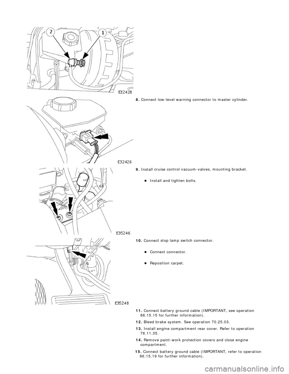
8. Conne ct
low-level warning connector to master cylinder.
9. Inst al
l cruise control vacuum-valves, mounting bracket.
пЃ¬Install and tigh
ten bolts.
10 . Conne
ct stop lamp switch connector.
пЃ¬Conne
ct
connector.
пЃ¬Re
posi
tion carpet.
11. Connect battery ground cable (IMPORTANT, see operation
86.15.15 for further information).
12. Bleed brake system. See operation 70.25.03.
13. Install engine compartment rear cover. Refer to operation
76.11.35.
14. Remove paint-work protection covers and close engine
compartment.
15 . Conne
ct battery ground cable (I
MPORTANT, refer to operation
86.15.19 for further information).
Page 422 of 2490
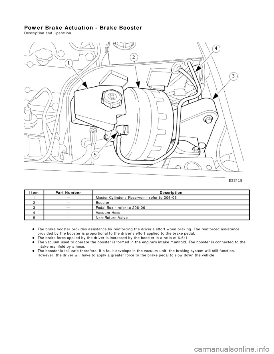
Power Brake Actuation - Brake Booster
Description and Operation
пЃ¬The brake b
ooster provides assi
stance by reinforcing the driver's effort when brakin g. The reinforced assistance
provided by the booster is proportional to the driver's effort applied to the brake pedal.
пЃ¬The brake force applied by
the driver is incr
eased by the booster in a ratio of 6.5:1.
пЃ¬Th
e vacuum used to operate the booster
is formed in the engine's intake manifold. The booster is connected to the
intake manifold by a hose.
пЃ¬The boost
er is fail-safe therefore, if a fault develops in
the vacuum unit, the braking system will still function.
However, the driver will have to apply a greater fo rce to the brake pedal to slow down the vehicle.
It e
m
Par
t
Number
De
scr
iption
1—Mas
t
er Cylinder / Reservoir - refer to 206-06
2—Booster
3—Pedal Box
- refer to 206-06
4—Vacuu
m
Hose
5—No
n
-Return Valve
Page 423 of 2490
Power Brake Actuatio
n - Brake Booster
Re
moval and Installation
Remov
al
• C
AUTIONS:
Replacement of nuts and bolts: Various thread-locking de vices are used on nuts and bolts throughout the vehicle.
These devices restrict the number of times a nut or bolt can be used. See section 100-00 for information.
Remove brake fluid spilla ge immediately from paint work, with clean water.
I
nstallation
1.
Position vehi
cle on a four-post lift.
2. Open engine compartment and fit paint work protection covers
to fenders.
3. Disconnect battery ground cable (IMPORTANT, see operation
86.15.19 for further information).
4. Remove engine compartment rear cover. Refer to operation
76.11.35.
5. Remove pedal housing, brake booster and master cylinder
assembly. Refer to operation 70.35.39.
6. Remove brake booster and master cylinder assembly. Refer to
operation 70.50.18.
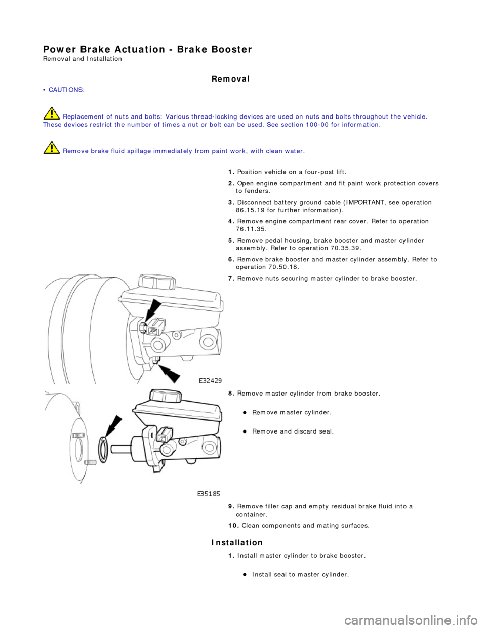
7. R
emove nuts securing master cylinder to brake booster.
8. R
emove master cylinder from brake booster.
пЃ¬Re
move master cylinder.
пЃ¬Remove an
d discard seal.
9. Remove filler cap and empty residual brake fluid into a
container.
10. Clean components and mating surfaces.
1. Install master cylinder to brake booster.
пЃ¬Inst
all seal to master cylinder.
Page 424 of 2490
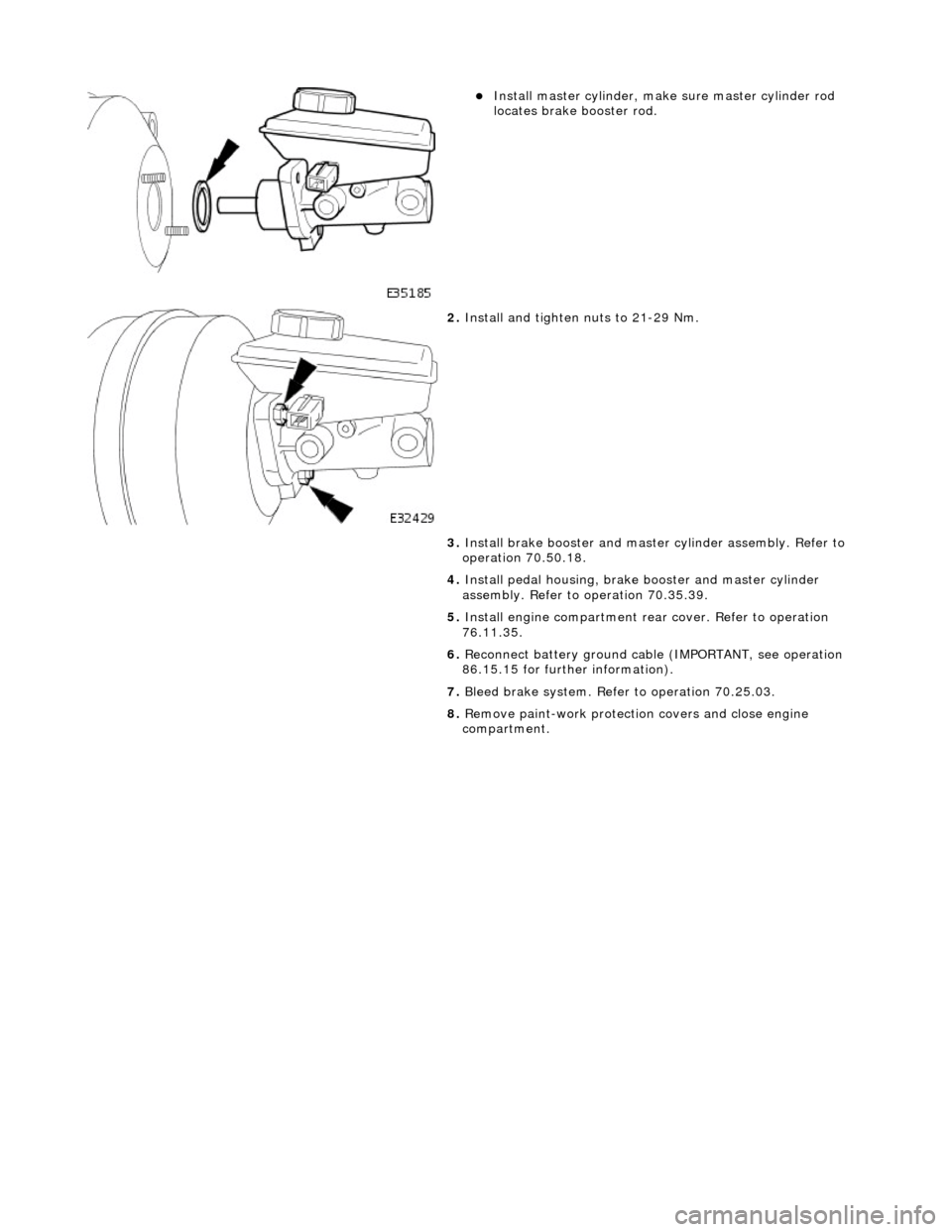
пЃ¬Instal
l master cylinder, make sure master cylinder rod
locates brake booster rod.
2. Inst al
l and tighten nuts to 21-29 Nm.
3. Install brake booster and master cylinder assembly. Refer to
operation 70.50.18.
4. Install pedal housing, brake booster and master cylinder
assembly. Refer to operation 70.35.39.
5. Install engine compartment rear cover. Refer to operation
76.11.35.
6. Reconnect battery ground cable (IMPORTANT, see operation
86.15.15 for further information).
7. Bleed brake system. Refer to operation 70.25.03.
8. Remove paint-work protection covers and close engine
compartment.
Page 425 of 2490
Power Brake Actuatio
n - Brake Boos
ter and Brake Master Cylinder
Re
moval and Installation
Remov
al
• C
AUTIONS:
Replacement of nuts and bolts: Various thread-locking de vices are used on nuts and bolts throughout the vehicle.
These devices restrict the number of times a nut or bolt can be used. See section 100-00 for information.
Remove brake fluid spilla ge immediately from paint work, with clean water.
1. Position vehi
cle on a four-post lift.
2. Move driver's seat fully rearward.
3. Open engine compartment and fit paint work protection covers
to fenders.
4. Disconnect battery ground cable (IMPORTANT, see operation
86.15.19 for further information).
5. Remove engine compartment rear cover. Refer to operation
76.11.35.
6. Remove pedal housing, brake booster and master cylinder
assembly. Refer to operation 70.35.39.
7. Remove reservoir filler cap and po ur residual brake fluid into a
container. Refit cap.
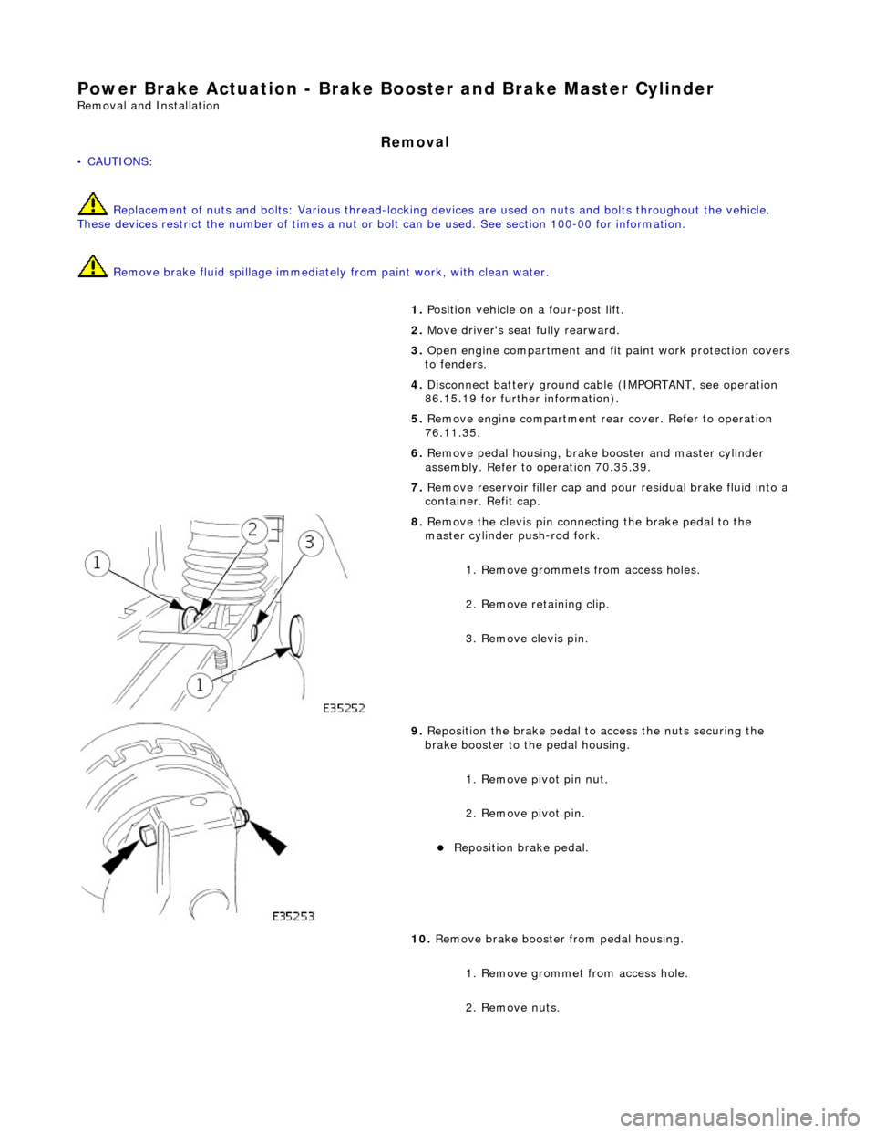
8. R
emove the clevis pin connecting the brake pedal to the
master cylinder push-rod fork.
1. Remove grommets from access holes.
2. Remove retaining clip.
3. Remove clevis pin.
9. Re
position the brake pedal to access the nuts securing the
brake booster to the pedal housing.
1. Remove pivot pin nut.
2. Remove pivot pin.
пЃ¬Reposition brake pedal.
10
.
Remove brake booster from pedal housing.
1. Remove grommet from access hole.
2. Remove nuts.
Page 427 of 2490
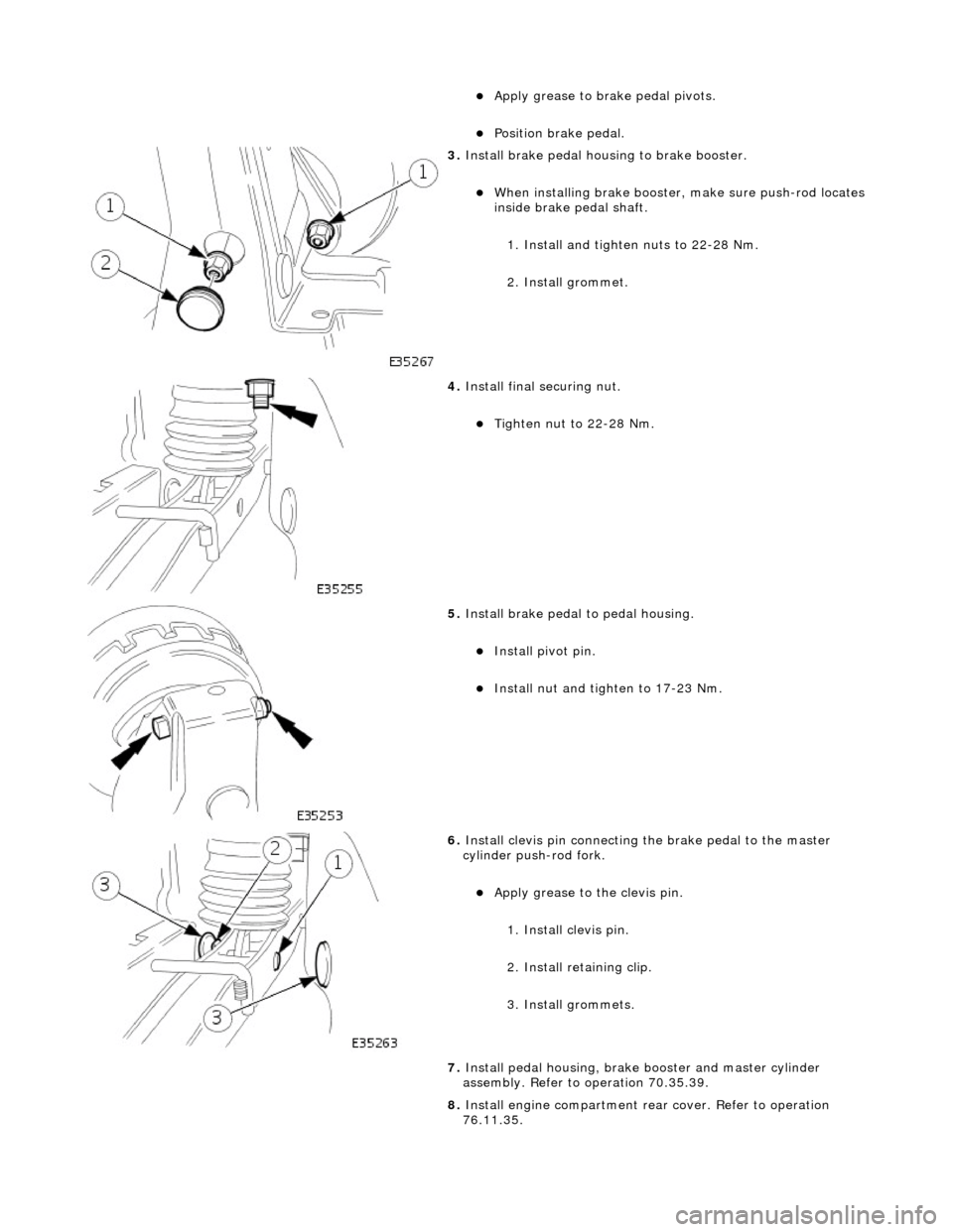
пЃ¬Apply grease to
brake pedal pivots.
пЃ¬Position brake pedal.
3. Install brake pedal hou
s
ing to brake booster.
пЃ¬Wh
en installing brake booster,
make sure push-rod locates
inside brake pedal shaft.
1. Install and tighten nuts to 22-28 Nm.
2. Install grommet.
4. Install
final securing nut.
пЃ¬Tigh
ten nut to 22-28 Nm.
5. Install brake pedal to pedal h
ousing.
пЃ¬Install piv
ot pin.
пЃ¬Install nu
t and tighten to 17-23 Nm.
6. Inst
all clevis pin connecting
the brake pedal to the master
cylinder push-rod fork.
пЃ¬Apply grease to
the clevis pin.
1. Install clevis pin.
2. Install retaining clip.
3. Install grommets.
7. Install pedal housing, brake booster and master cylinder
assembly. Refer to operation 70.35.39.
8. Install engine compartment rear cover. Refer to operation
76.11.35.
Page 428 of 2490

9.
Reconn
ect battery ground cable (IMPORTANT, see operation
86.15.15 for further information).
10. Bleed brake system. Refer to operation 70.25.03.
11. Remove paint-work protection covers and close engine
compartment.
Page 432 of 2490
пЃ¬It is a reciprocating two
-circuit pu
mp in which one brake circuit is as signed to each pump circuit.
пЃ¬It supplies th
e fluid pressure and vo
lume to supply the brake circuits under ABS and Traction control.
пЃ¬The pump is driven by an electri
c motor, with the pump
housing incorporating two lo w pressure accumulators and
damping chambers for each brake circuit.
пЃ¬The ac cu
mulator stores the pressure and smooths out the output pu
lses from the pump.
ABS Warning Lamp
The sys
tem will be set in a fail-safe mode if a problem is de
tected; a warning lamp on the instrument panel will notify the
driver there is a problem.
Anti-Lock Braking Sy
stem (ABS)
The AB
S components are combined with
an hydraulic booster and a tandem master cylinder to provide a two circuit braking
system. The system comprises, four wheel speed sensor s, a brake control modulator and an ABS warning lamp.
Should a wheel start to lock-up during braking a signal tr ansmitted from the wheel speed sensor to the brake control
modulator will start the hydraulic pump. The brake control modula tor will close the input valve of the line connected to the
locked-wheel to stop any increase in fluid pressure to the br ake caliper. If this fails to prevent the wheel locking, the
pressure in the caliper will be decreased by opening the return valve until th e wheel starts accelerating again. The fluid
pressure from the return va lve is directed into the low pressure accumulator, housed in the pump.
From the low pressure accumulator, fl uid is pumped through the damping cham ber to the brake master cylinder. The
pressure to the brake caliper will then be increased in small steps to maintain maximum adhesion between the tire and road
surface. This is achieved by closing the return valve, and opening the input valve and using the hydraulic pump to increase
the pressure.
Although the system senses all four wheels independently, the rear wheels are regulated as a pair. If a sensor on a rear
wheel detects a wheel decelerating rapidly, then the fluid pressure to both wheels is reduced. The fluid pressure is then
dictated by the wheel having the lowe st adhesion with the road surface.
The ABS system will be set in a fail-safe mode if a problem is detected; a warn ing lamp on the instrument panel will notify
the driver there is a problem. The brake system will still operate conventionally and with the same standard of performance
as a vehicle not equipped with ABS.
Automa tic Stability Control (ASC)
Th
e ASC utilizes the ABS sensing arrangement to provide the maximum traction force to propel the vehicle.
The ASC is switched on when the engine is started. The system can be switched off by pressing the 'ASC OFF' (the switched
is marked 'TRAC OFF' on vehicles fitted with traction control). The switch, which is situated in the center console switchpack,
lights up to warn that the system is sw itched off. An 'ASC' amber warning light flashes on the instrument panel when the
system detects a spinning wheel.
The ASC system uses engine intervention to reduce the torque delivered to the drive wheels to prevent them spinning.
Engine torque is re duced in three ways:
пЃ¬The
throttle is moved towards the closed position.
пЃ¬The ignition is retarded. пЃ¬F
u
el is cut-off at the cylinder injectors.
Wheel spin is detected by the wheel sp eed sensors and communicated to the AB S/TCCM. The ABS/TCCM uses information
from the controller area network (CAN) to calculate the torque that the engine should produce to stop the wheel spinning.
Torque reductions are then requested from the engine control module (ECM ) through the CAN. The throttle is then
positioned to provide the target torque, which has been calculated to prevent wheel spin. During the transient phase of
torque reduction the fuel is cut-off and th e ignition retarded Both the fuel cut-off an d ignition retard will be restored to
normal when the throttle is set to its new position.
The ASC uses a brake control modulator with six solenoid va lves: three normally open inlet valves and three normally
Page 436 of 2490
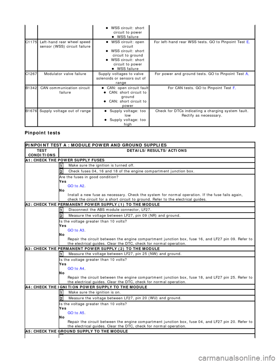
Pinpoint tests
пЃ¬W
S
S circuit: short
circuit to power
пЃ¬WSS f
ailure
C1
175Left -hand re
ar wheel speed
sensor (WSS) circuit failure
пЃ¬W S
S circuit: open
circuit
пЃ¬WS
S circuit: short
circuit to ground
пЃ¬W S
S circuit: short
circuit to power
пЃ¬WSS f
ailure
F
or l
eft-hand rear WSS test
s. GO to Pinpoint Test E.
C1267Modulat or valv
e failure
Supply volt
ages
to valve
solenoids or sensors out of range
Fo
r power and ground tests. GO to Pinpoint Test
A.
B1342CAN co
mmunication circuit
failure
пЃ¬CAN :
open circuit fault
пЃ¬CAN:
short circuit to
ground
пЃ¬CAN :
short circuit to
power
Fo
r CAN tests. GO to Pinpoint Test
F.
B1676Supply volt
age out of range
пЃ¬Supply voltage:
too
low
пЃ¬Supply volt age:
too
high
Check fo
r DTCs indicating a charging system fault.
Rectify as necesssary.
PI
NPOINT TEST A : MODULE
POWER AND GROUND SUPPLIES
TES
T
CONDITIONS
D E
TAILS/RESULTS/ACTIONS
A
1
: CHECK THE POWER SUPPLY FUSES
Make sure the igniti
on is turned off. 1
Chec
k fuses 04, 16 and 18 of the engine compartment junction box.
2
Are th
e fus
es in good condition?
Yes GO to A2
.
No
Install a new f
use as
necessary. Check the syst em for normal operation. If the fuse fails again,
check the circuit for a short circuit to ground. Refer to the electrical guides.
A2: CHECK THE PERMANENT
POWER SUPPLY (1) TO THE MODULE
Disc
onnect the ABS module connector, LF27.
1
Measure the voltage between LF
2
7, pin 09 (NR) and ground.
2
Is the vol
t
age greater than 10 volts?
Yes GO to A3
.
No Re
pair the circuit between the engine compartment
junction box, fuse 16, and LF27 pin 09. Refer to
the electrical guides. Clear the DTC, check for normal operation.
A3: CHECK THE PERMANENT
POWER SUPPLY (2) TO THE MODULE
Meas
ure t
he voltage between LF27, pin 25 (NW) and ground.
1
Is the vol
t
age greater than 10 volts?
Yes GO to A4
.
No
Re
pair the circuit between the engine compartment ju
nction box, fuse 18, and LF27 pin 25. Refer to
the electrical guides. Clear the DTC, check for normal operation.
A4: CHECK
THE IGNITION POWER SUPPLY TO THE MODULE
Make sure the ignition is on. 1
Measure the
voltage between LF 2
7, pin 20 (WU) and ground.
2
Is the vol
t
age greater than 10 volts?
Yes GO to A5
.
No Re
pair the circuit between the engine compartment ju
nction box, fuse 04, and LF27 pin 20. Refer to
the electrical guides. Clear the DTC, check for normal operation.
A5: CHECK
THE GROUND SUPPLY TO THE MODULE
Page 440 of 2490
Anti-Lock Control - Anti-Lock Brake System (ABS) Module
Remo
val and Installation
Remov
a
l
• C
A
UTIONS:
Replacement of nuts and bolts: Various thread-locking de vices are used on nuts and bolts throughout the vehicle.
These devices restrict the number of times a nut or bolt can be used. See section 100-00 for information.
Remove brake fluid spilla ge immediately from paint work, with clean water.
Sp
ecial Tool(s)
Brake Pedal
H
old Tool
JDS 9013
1. Disc onne
ct battery ground cable (IMPORTANT, see operation
86.15.19 for further information).
2. Position vehicle on a four-post lift.
3. Open engine compartment and fit paint work protection covers
to fenders.
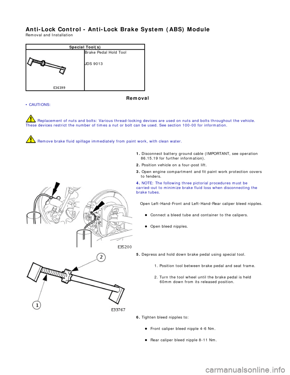
4. NOTE : Th
e following three pictorial procedures must be
carried-out to minimize brake fl uid loss when disconnecting the
brake tubes.
Open Left-Hand-Front and Left-H and-Rear caliper bleed nipples.
пЃ¬Connect a
bleed tube and co
ntainer to the calipers.
пЃ¬Op
en bleed nipples.
5. Depress and hold down brake pedal u s
ing special tool.
1. Position tool between brake pedal and seat frame.
2. Turn the tool wheel unti l the brake pedal is held
60mm down from its released position.
6. Tighten bleed nipples to:
пЃ¬Front caliper blee d nipple 4-6 Nm.
пЃ¬Rear
caliper bleed nip
ple 8-11 Nm.