engine JAGUAR X308 1998 2.G Manual Online
[x] Cancel search | Manufacturer: JAGUAR, Model Year: 1998, Model line: X308, Model: JAGUAR X308 1998 2.GPages: 2490, PDF Size: 69.81 MB
Page 479 of 2490
Power Steering - Power Steering
Description an
d Operation
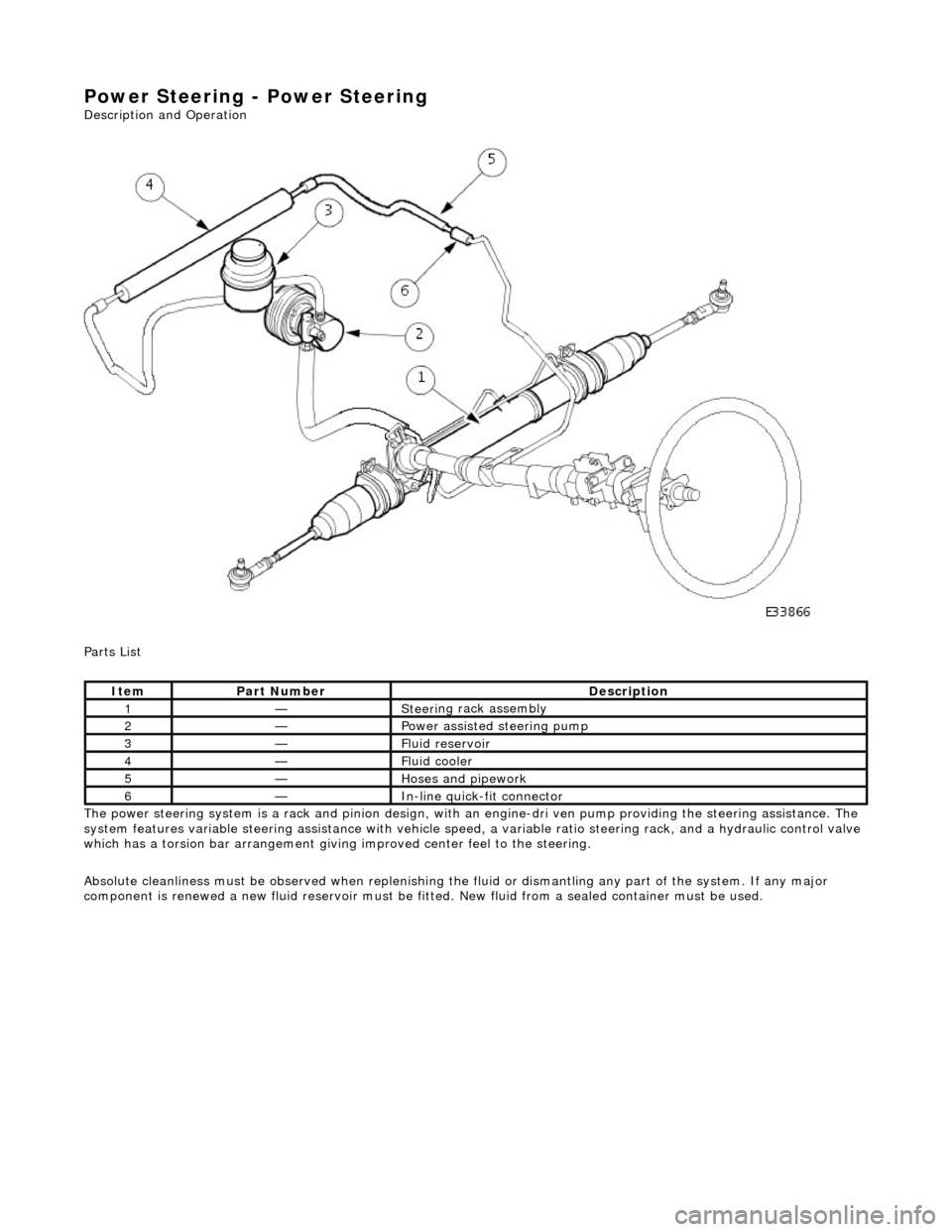
Parts List
The power steering system is a rack and pinion design, with an engine-dri ve n pump providing the steering assistance. The
system features variable steering assistance with vehicle spee d, a variable ratio steering rack, and a hydraulic control valve
which has a torsion bar arrangement giving improved center feel to the steering.
Absolute cleanliness must be observed wh en replenishing the fluid or dismantling any part of the system. If any major
component is renewed a new fluid rese rvoir must be fitted. New fluid from a sealed container must be used.
It
em
Par
t Number
De
scription
1—Steeri
ng rack assembly
2—Power as
sisted steering pump
3—F
luid reservoir
4—F
luid cooler
5—Hoses and pipework
6—In-
line quick-fit connector
Page 484 of 2490
P a
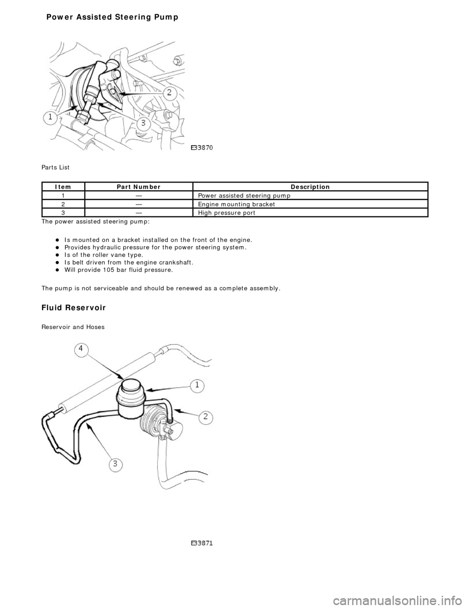
rts List
The power assisted steering pump:
пЃ¬Is mo u
nted on a bracket installe
d on the front of the engine.
пЃ¬Provides hydraul
ic pressure fo
r the power steering system.
пЃ¬Is of the roll
er vane type.
пЃ¬Is belt driven from th
e en
gine crankshaft.
пЃ¬Will provide 1
05 bar f
luid pressure.
The pump is not serviceable and should be renewed as a complete assembly.
Fluid Reservoir
Re
servoir and Hoses
Ite
m
Par
t
Number
De
scr
iption
1—Power as
si
sted steering pump
2—Engine
m
ounting bracket
3—High
pressure port
Power Assisted Steering Pump
Page 485 of 2490
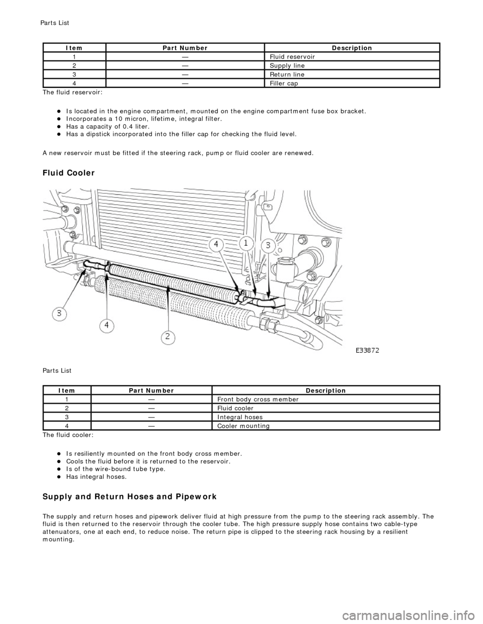
The fluid reservo
ir:
пЃ¬Is lo
cated in the engine compartment, mounted on the engine compartment fuse box bracket.
пЃ¬Incorporates
a 10 micron, li
fetime, integral filter.
пЃ¬Has a cap
acity of 0.4 liter.
пЃ¬Has a dipsti
ck incorporated into the filler cap for checking the fluid level.
A new reservoir must be fitted if the steering rack, pump or fluid cooler are renewed.
Fluid C
ooler
P
arts List
The fluid cooler:
пЃ¬Is
resiliently mounted on th
e front body cross member.
пЃ¬Coo
ls the fluid before it is
returned to the reservoir.
пЃ¬Is
of the wire-bound tube type.
пЃ¬Has i
ntegral hoses.
Supply and Return Hoses a
nd Pipework
The supply and return h
oses and
pipework deliver fluid at high pressure from the pump to th e steering rack assembly. The
fluid is then returned to th e reservoir through the cooler tube. The high pressure supply hose contains two cable-type
attenuators, one at each end, to reduce nois e. The return pipe is clipped to the steering rack housing by a resilient
mounting.
It
em
Par
t Number
De
scription
1—Fl
uid reservoir
2—Supply line
3—R
eturn line
4—Fi
ller cap
It
em
Par
t Number
De
scription
1—Front body cross member
2—F
luid cooler
3—Inte
gral hoses
4—Cooler m
ounting
P
arts List
Page 490 of 2490
Power Steering - Power Steering
Diagn
osis and Testing
Refer to the Description and Operation sub-section for details of the power operated steering system and Servotronic control
system.
Power Steer ing Pressure Test
Test Equ
i
pment
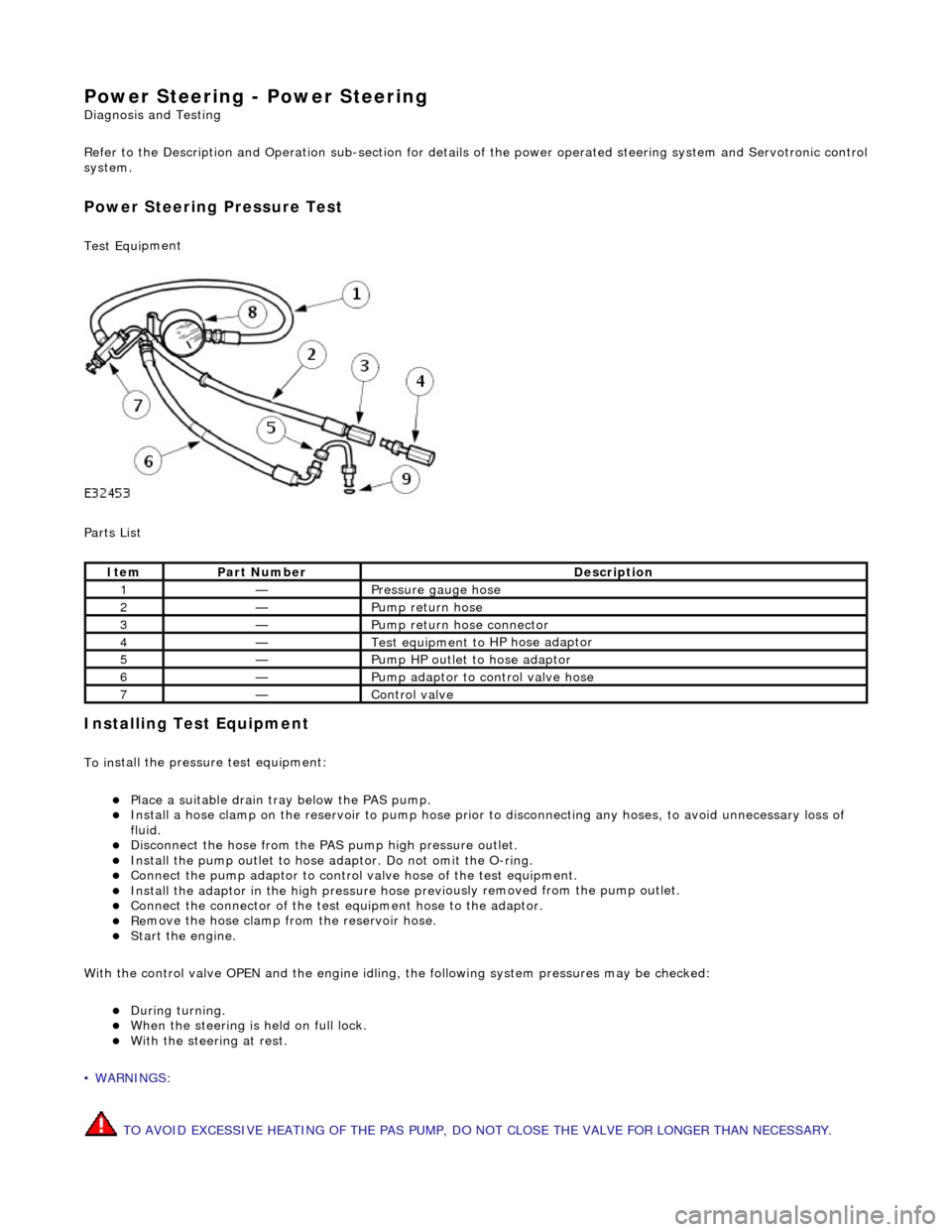
Parts List
In
stalling Test Equipment
To
in
stall the pressure test equipment:
пЃ¬Pla
c
e a suitable drain tray below the PAS pump.
пЃ¬Install a hose clamp
on
the re
servoir to pump hose prior to disconnecting any hoses, to avoid unnecessary loss of
fluid.
пЃ¬Di sc
onnect the hose from the PAS pump high pres
sure outlet.
пЃ¬Ins
tall the pump outlet to hose ad
aptor. Do not omit the O-ring.
пЃ¬Conn
ect the pump adaptor to control valve hose of the test equipment.
пЃ¬Install th
e adaptor in the high pressure hose previ
ously re
moved from the pump outlet.
пЃ¬Conne
ct the connector of the test equipment hose to the adaptor.
пЃ¬R
e
move the hose clamp fro
m the reservoir hose.
пЃ¬Start th
e engine.
With the control valve OPEN and the engine idling , the following system pressures may be checked:
пЃ¬Du
ring turning.
пЃ¬W
h
en the steering is
held on full lock.
пЃ¬With
the steeri
ng at rest.
• WARNINGS:
TO AVOID EXCESSIVE HEATING OF THE PAS PUMP, DO NOT CLOSE THE VALVE FOR LONGER THAN NECESSARY.
Ite
m
Par
t
Number
De
scr
iption
1—Pressure
gauge hose
2—Pump return hose
3—Pump return hose connector
4—Test equi
pment to
HP hose adaptor
5—Pump HP outlet to hose adaptor
6—Pump adaptor
to control valve hose
7—Control valve
Page 510 of 2490
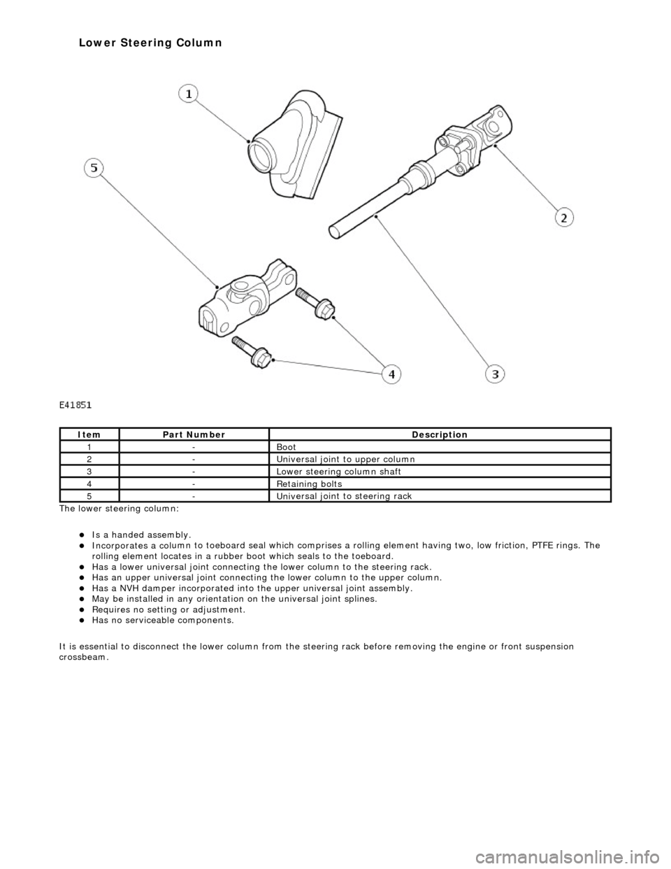
The lower steeri ng col
umn:
пЃ¬Is a han
ded assembly
.
пЃ¬Incorporates
a col
umn to toeboard seal
which comprises a rolling element having two, low friction, PTFE rings. The
rolling element locates in a rubber b oot which seals to the toeboard.
пЃ¬Has a lowe
r universal joint connecting the
lower column to the steering rack.
пЃ¬Has an upper un
iversal joint connecting
the lower column to the upper column.
пЃ¬Has a NVH damper in
corporated into
the upper universal joint assembly.
пЃ¬May be installed in an
y orientation on the universal joint splines.
пЃ¬R
e
quires no setting or adjustment.
пЃ¬Has no s
e
rviceable components.
It is essential to disconnect the lower column from the steer ing rack before removing the engine or front suspension
crossbeam.
It e
m
Par
t
Number
De
scr
iption
1-Boot
2-Uni
v
ersal joint to upper column
3-Lower steeri
ng col
umn shaft
4-R
e
taining bolts
5-Uni
v
ersal joint to steering rack
Lower Steering Column
Page 516 of 2490
IGNITION.
All circuits, except the star
ter motor, are activated. The key rema ins in this position when driving.
Position 'III'
START. The starter operates for as long as the key is held in this position, ag ainst spring pressure. If the engine fails to
start, the key must be returned to position 'I' befo re another start is attempted.
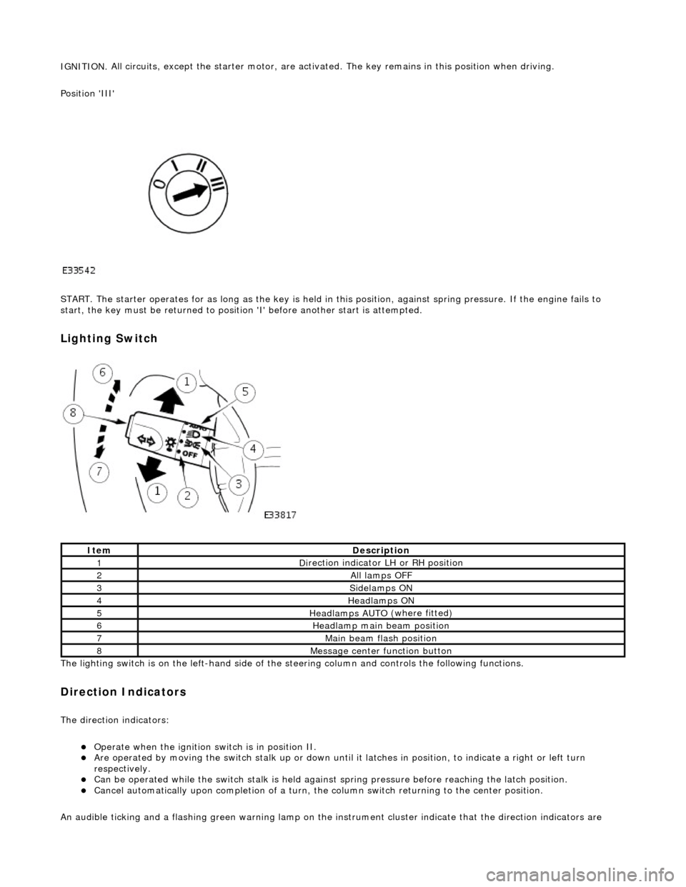
Lighting Switch
The li
ghting switch is on the left-h
and side of the steering column and controls the following functions.
Direction Indicators
The direction in
dicators:
пЃ¬Operate
when the ignition switch is in position II.
пЃ¬Are operat
ed by movi
ng the switch stalk up or down until it latches in position, to in
dicate a right or left turn
respectively.
пЃ¬Can be o p
erated while the switch stalk is held against
spring pressure before reaching the latch position.
пЃ¬Cancel
automatically upon completion of a turn, the
column switch returning to the center position.
An audible ticking and a flashing green warning lamp on the in strument cluster indicate that the direction indicators are
Ite
m
De
scr
iption
1D
i
rection indicator LH or RH position
2All lamps OFF
3Side
lamps ON
4Headlamps ON
5Headlamps AUT O
(where fitted)
6He
adlam
p main beam position
7Mai
n
beam flash position
8M
e
ssage center function button
Page 520 of 2490
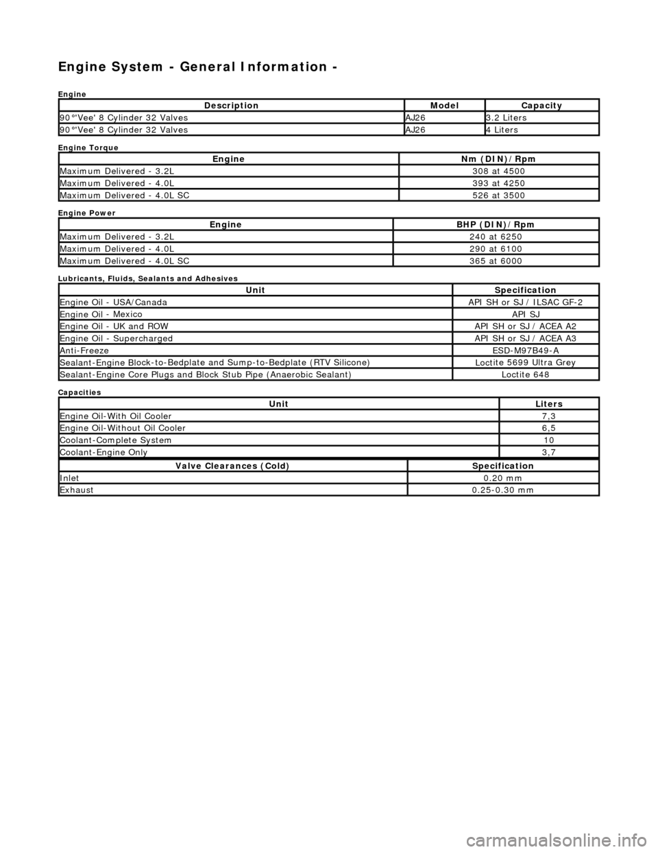
Engine System - General Inform
ation -
Eng
ine
Engine Torque
Engine Power
Lubricants, Fluids, Sealants and Adhesives
Capacities
Descr
iption
Mode
l
Capaci
ty
90
В°'Ve
e' 8 Cylinder 32 Valves
AJ263.
2 L
iters
90
В°'Ve
e' 8 Cylinder 32 Valves
AJ264 Li
te
rs
EngineNm (D
I
N)/Rpm
M
a
ximum Delivered - 3.2L
3
08 at
4500
M
a
ximum Delivered - 4.0L
3
93 at
4250
M
a
ximum Delivered - 4.0L SC
5
26 at
3500
EngineBH
P (D
IN)/Rpm
M
a
ximum Delivered - 3.2L
2
40 at
6250
M
a
ximum Delivered - 4.0L
2
90 at
6100
M
a
ximum Delivered - 4.0L SC
3
65 at
6000
UnitS
p
ecification
Engine Oil
-
USA/Canada
API SH or SJ
/ ILSAC G
F-2
Engine
Oil
- Mexico
API SJ
Engine
Oil
- UK and ROW
API SH or SJ
/ ACEA A2
Engine Oil -
Supercharged
API SH or SJ
/ ACEA A3
Anti-Freez
e
ESD-M97B
49
-A
Sealant-Engine B
l
ock-to-Bedplate an
d Sump-to-Bedplate (RTV Silicone)
Loct
ite 5699 Ultra Grey
Sealant-Engine
C
ore Plugs and Bloc
k Stub Pipe (Anaerobic Sealant)
Loctite 648
UnitLit
ers
Engine
Oil-W
ith Oil Cooler
7,
3
Engine Oil-W i
thout Oil Cooler
6,
5
Cool ant
-Complete System
10
Coo
lan
t-Engine Only
3,
7
Val v
e Clearances (Cold)
S
p
ecification
Inlet0.
20
mm
Exhaus
t0.25
-0.30 mm
Page 521 of 2490
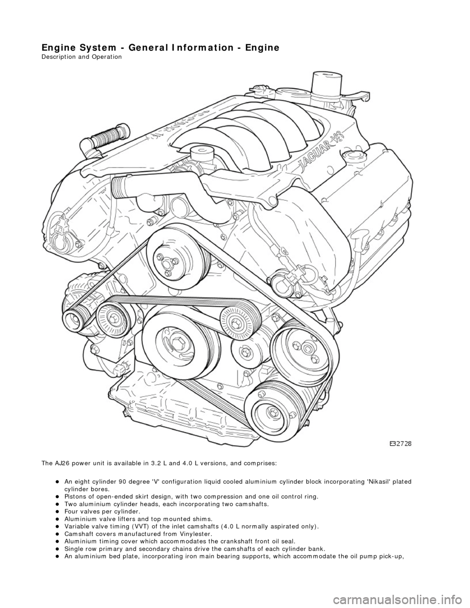
Engine System - General Infor
mation - Engine
Description an
d Operation
The AJ26 power unit is available in 3.2 L and 4.0 L versions, and comprises:
пЃ¬An eight cylinder 9
0 degree 'V' config
uration liquid cooled aluminium cylinder block incorporating 'Nikasil' plated
cylinder bores.
пЃ¬Pi
stons of open-ended skirt design, with
two compression and one oil control ring.
пЃ¬Two al
uminium cylinder heads, each
incorporating two camshafts.
пЃ¬F
our valves per cylinder.
пЃ¬Al
uminium valve lifters and top mounted shims.
пЃ¬Vari
able valve timing (VVT) of the inlet camshafts (4.0 L normally aspirated only).
пЃ¬Camshaft
covers manufactured from Vinylester.
пЃ¬Al
uminium timing cover which accommodat
es the crankshaft front oil seal.
пЃ¬Sin
gle row primary and secondary chains dr
ive the camshafts of each cylinder bank.
пЃ¬An alu
minium bed pl
ate, incorporating iron main bearing supports, which accomm odate the oil pump pick-up,
Page 522 of 2490
diverter val
ve (if fitted) and oil filter.
пЃ¬Main
bearings
which are grooved in the upper positions and plain in
the lower positions. They are manufactured from
aluminium / tin material.
пЃ¬A c
rankshaft with under
cuts and rolled fillets for extra strength.
пЃ¬Fracture
-split connecting rods in sintered-forged steel.
пЃ¬Brackets
bolted to the front of
the cylinder
block are used to mo unt all accessories.
пЃ¬A sin
gle, seven ribbed vee belt
drives the accessories.
пЃ¬An au
tomatic belt tensioner for the front accessory drive,
incorporating a wear indicator.
пЃ¬An advanced en
gine management system inco
rporating electronic throttle control.
пЃ¬The un
it meets the requirements of the CARB OBDII USA legislation.
Ancillary Systems
The an
ci
llary systems, driven by the engine, each have a
detailed Description and Operation along with Diagnostic
Procedures, and Removal and Installation instructions ; refer to the following sections of this manual:
пЃ¬Power Steeri
ng Pump - Section 211-02
пЃ¬Ai
r Conditioning Compressor - Sectio
n 412-03
пЃ¬Engine
C
ooling Pump - Section 303-03
пЃ¬Generator
- Sectio
n 414-02
The drive belt, idler pulley and automatic tensioner are described in Section 303-05.
The engine starting system is described in Section 303-06.
En
gine Management and Emission Control System
Engine Control Modu
le (ECM)
Engine
management and exhaust emissions are controlled by the ECM, which has the
following main functions:
пЃ¬Fu
el injection
пЃ¬Idle
s
peed
пЃ¬Ignition пЃ¬Ev
aporative loss system
пЃ¬Engine
cooling fans пЃ¬Clim
ate control compressor clutch demand
The microprocessor within the ECM receiv es signals from various sensors and other modules and uses a pre-determined
program to compute engine management functions.
Adaptive functions are incorporated in the ECM to cater for co ntinuous adjustments to its computations to suit prevailing
conditions. Because the system also controls emissions to suit all modes, neither CO levels nor idle speed require service
attention or adjustment, except if an error should occur.
On Board Diagnostics are controlled by the ECM with the continuous monitoring of incoming signals and the subsequent
verification against what the module expects to 'see'. Should a si gnal be incorrect or missing, the ECM will substitute a fixed
value to provide the 'limp home mode' and alert the driver of the problem. Fixed values may be adopted for:
пЃ¬Transmission oil
temperature
пЃ¬Mechanica
l
guar
d position
пЃ¬Throttle blade angle пЃ¬Camshaft position
пЃ¬Inta
k
e air temperature
Diagnostic trouble codes (DTC), including OBD II codes, are stored in the ECM memo ry and can be read by an appropriate
retrieval tool.
Should either the ECM or TCM fa il, ensure that the control housing cooling fan is operating correctly. Failure of the cooling
fan MUST be rectified before renewing a control module and details of a fa n failure should accompany a returned control
module.
Page 525 of 2490
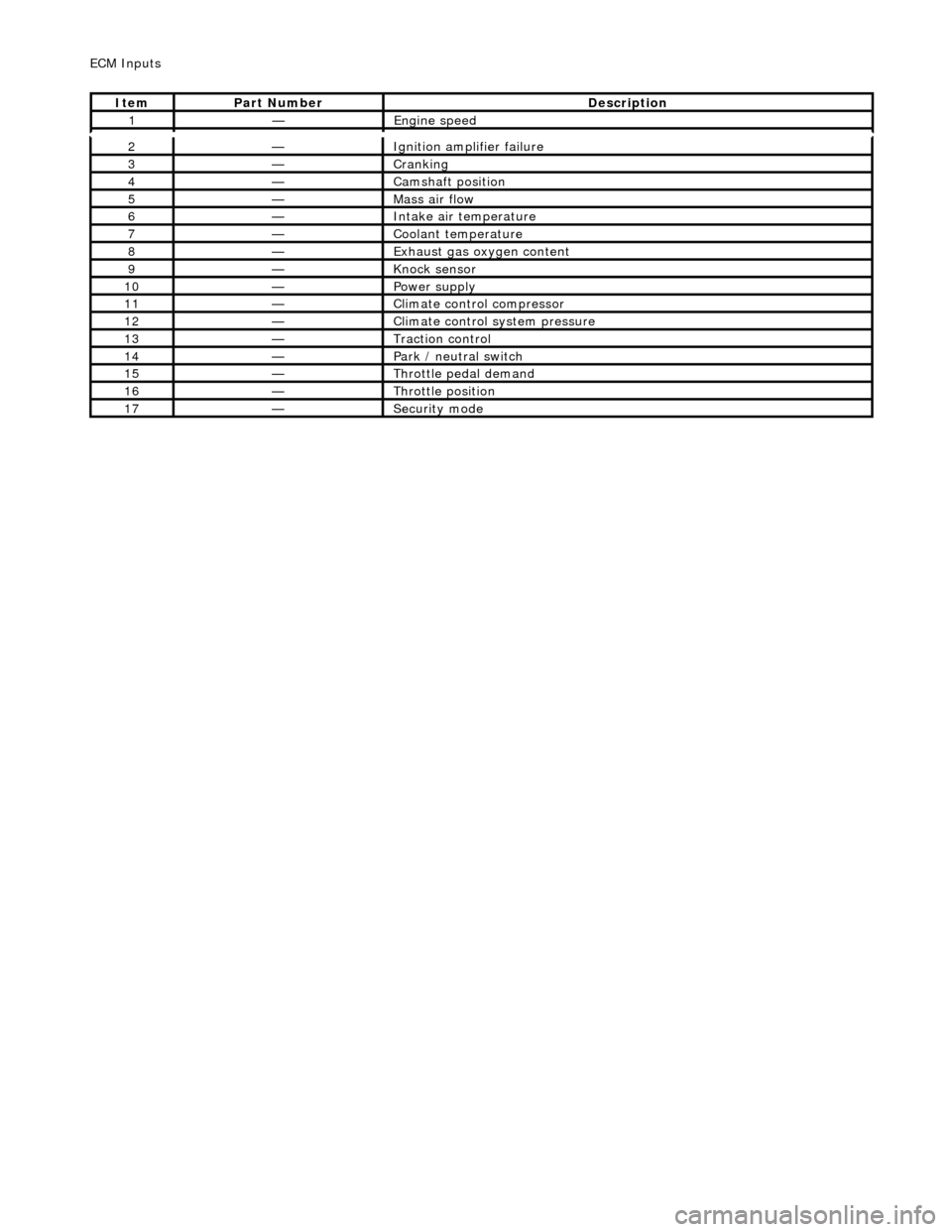
2—Ignition ampl
ifier failure
3—Crankin
g
4—Camshaft position
5—Mass ai
r flow
6—Inta
ke air temperature
7—Coo
lant temperature
8—Exhaus
t gas oxygen content
9—Knock
sensor
10—Power supply
11—Cl
imate control compressor
12—Cli
mate control system pressure
13—Traction contr
ol
14—Park / neutral
switch
15—Throttle pedal demand
16—Thro
ttle position
17—Securi
ty mode
ECM In
puts
It
em
Par
t Number
De
scription
1—Engine
speed