torque JAGUAR X308 1998 2.G Manual PDF
[x] Cancel search | Manufacturer: JAGUAR, Model Year: 1998, Model line: X308, Model: JAGUAR X308 1998 2.GPages: 2490, PDF Size: 69.81 MB
Page 886 of 2490

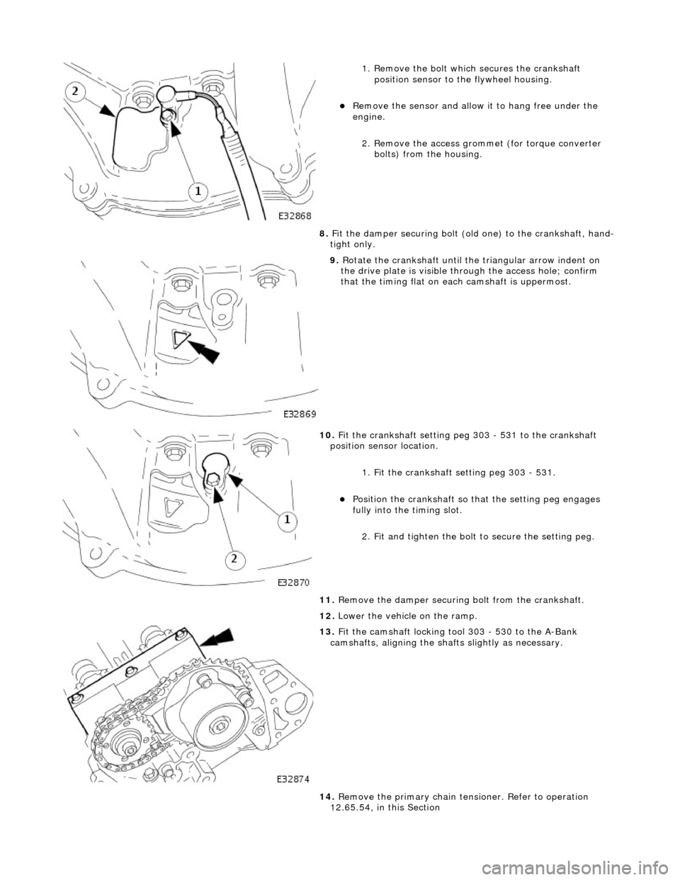
1. Remove the bolt which secures the crankshaft position sensor to the flywheel housing.
пЃ¬Remove the sensor and allow it to hang free under the
engine.
2. Remove the access grommet (for torque converter bolts) from the housing.
8. Fit the damper securing bolt (old one) to the crankshaft, hand-
tight only.
9. Rotate the crankshaft until the triangular arrow indent on
the drive plate is visible thro ugh the access hole; confirm
that the timing flat on ea ch camshaft is uppermost.
10. Fit the crankshaft setting peg 303 - 531 to the crankshaft
position sensor location.
1. Fit the crankshaft setting peg 303 - 531.
пЃ¬Position the crankshaft so that the setting peg engages
fully into the timing slot.
2. Fit and tighten the bolt to secure the setting peg.
11. Remove the damper securing bolt from the crankshaft.
12. Lower the vehicle on the ramp.
13. Fit the camshaft locking tool 303 - 530 to the A-Bank
camshafts, aligning the shafts slightly as necessary.
14. Remove the primary chain tens ioner. Refer to operation
12.65.54, in this Section
Page 912 of 2490

пЃ¬Align th
e engine front mountings and fit the securing nuts.
пЃ¬Tighte
n to the stated torque value.
3. Operate the crane controls and the ramp simultaneously (with
assistance) to raise the vehicle to a convenient working height.
4. Po
sition the transmission jack and raise it to take the weight of
the transmission. Fit and adjust the chains to secure the
transmission to the jack.
5. Fit th
e engine rear mounting bracket.
пЃ¬Fi
t the four bolts which secu
re the crossmember to the
body.
пЃ¬Fi t t
he bolt which secures the
engine rear mounting rubber
to the transmission.
6. Tigh ten th
e rear mounting bolts
to the stated torque figure.
7. Release and remove the transmission jack.
8. Operate the crane controls and the ramp simultaneously (with
assistance) to lower the vehicle to a convenient working height.
9. Lower th e cran
e and remove th
e chain assembly and lifting
eyes.
Page 914 of 2490

пЃ¬Repeat
the above procedure for the other side.
16 . Connect
the driveshaft (propshaft
) flange to the transmission
output flange.
пЃ¬F i
t the three bolts which secure the flange.
17 . F
it the downpipe catalytic converters.
1. Fit a new gasket to the downpipe flange and fit the
downpipe assembly. to the manifold.
пЃ¬F i
t the bolts which secure
the downpipe to the lower
mounting bracket.
пЃ¬Repeat the above operation
s
for the other downpipe
catalytic converter.
18 . F
rom above the vehicle, tighte
n the manifold flange nuts, A-
Bank and B-Bank flanges, to the correct torque.
19. Fit the front muffler assembly.
пЃ¬Locate the front muf fler into the
downpipe catalytic
converters.
20. Move the front muffler forwar d to allow the intermediate
mufflers to be connected.
Page 915 of 2490

пЃ¬Connect
the front muffler to
the intermediate muffler,
noting the alignment of the indicator rings.
пЃ¬W
ith the front muffler positioned correctly, tighten the
clamps (left-hand and right-hand sides) to the catalytic
converter.
21
.
Tighten the clamps (left-hand and right-hand sides),
intermediate mufflers to front muffler.
22
.
Tighten the downpipe bracket se curing bolts to the correct
torque
23
.
Connect the oil cooler pipes (w here fitted) to the engine.
1. Remove the blanking plugs from the pipes and from the mating unions on the engine.
2. Fit new O-ring seals to the pipes and lubricate with new engine oil.
3. Connect the pipes to the engine and fit the clamping
plate and bolt.
24. Lower the vehicle on the ramp.
25. Connect the heater and brake servo hoses.
1. Connect the heat er return hose.
2. Connect the heater feed hose and secure the locking
lever.
Page 1001 of 2490

Engine Cooling - Water Pump4.0L NA V8 - AJ27/ 3.2L NA V8 - AJ26
Re
moval and Installation
Remov
al
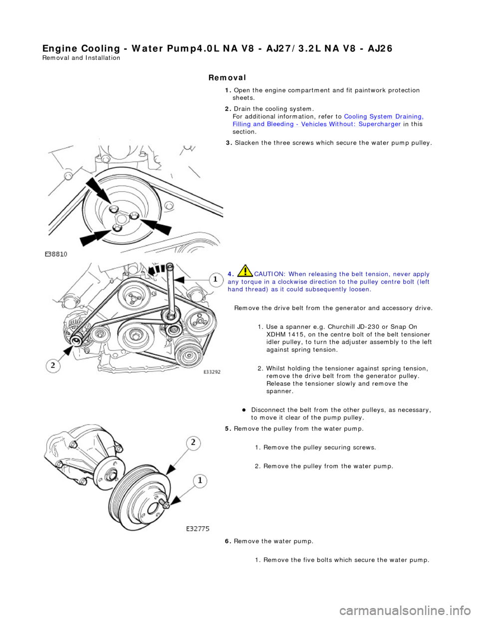
1.
O
pen the engine compartment and fit paintwork protection
sheets.
2. Drain the cooling system.
For additional information, refer to Cooling System Draining,
Fillin
g and Bleeding
- Vehicles W
ithout: Supercharger
in
this
section.
3. Sl
acken the three screws which
secure the water pump pulley.
4. CAUTI
ON: When releasing the
belt tension, never apply
any torque in a clockwise direction to the pulley ce ntre bolt (left
hand thread) as it could subsequently loosen.
Remove the drive belt from the generator and accessory drive.
1. Use a spanner e.g. Churchill JD-230 or Snap On XDHM 1415, on the centre bo lt of the belt tensioner
idler pulley, to turn the adju ster assembly to the left
against spring tension.
2. Whilst holding the tensioner against spring tension, remove the drive belt from the generator pulley.
Release the tensioner sl owly and remove the
spanner.
пЃ¬D
isconnect the belt from the ot
her pulleys, as necessary,
to move it clear of the pump pulley.
5. Re
move the pulley from the water pump.
1. Remove the pulley securing screws.
2. Remove the pulley from the water pump.
6. Remove the water pump.
1. Remove the five bolts wh ich secure the water pump.
Page 1004 of 2490

Engine Cooling - Water Pump4.0L SC V8 - AJ26
Remo
val and Installation
Remov
a
l
1.
Op
en the engine compartment and fit paintwork protection
sheets.
2. Drain the cooling system.
For additional information, refer to Cooling System Draining,
Filling and Bleedin
g
- Vehicles With
: Supercharger in this
section.
3. Remove the supercharger driv e belt. Refer to Operation
18.50.08.
4. Slacken the three screws whi
ch
secure the water pump pulley.
5. CAUTIO
N: When releasing the
belt tension, never apply
any torque in a clockwise direction to the pulley ce ntre bolt (left
hand thread) as it could subsequently loosen.
Remove the drive belt from the generator and accessory drive.
1. Use a spanner e.g. Churchill JD-230 or Snap On XDHM 1415, on the centre bo lt of the belt tensioner
idler pulley, to turn the adju ster assembly to the left
against spring tension.
2. Whilst holding the tensioner against spring tension, remove the drive belt from the generator pulley.
Release the tensioner sl owly and remove the
spanner.
пЃ¬Di
sconnect the belt from the ot
her pulleys, as necessary,
to move it clear of the pump pulley.
6. Remove t
he pulley from the water pump.
1. Remove the pulley securing screws.
2. Remove the pulley from the water pump.
7. Remove the water pump.
Page 1007 of 2490

W
ater Pump Pulley Vehicles Without: Supercharger
26.50.05
Removal
1. Open the engine compartment and fit paintwork protection sheets.
2
. Slacken the three screws which secure the water pump pulley.
3
.
C
AUTION:
When releasing the belt tension, never apply any torque in a clockwise direction to the pulley
centre bolt (left hand thread) as it could subsequently loosen.
Remove the drive belt from the generator and accessory drive. 1. Use a spanner e.g. Churchill JD-230 or Snap On XDHM 1415, on the centre bolt of the belt tensioner idler pulley, to turn the adjuster assembly to the left against spring tension.
Page 1009 of 2490

W
ater Pump Pulley Vehicles With: Supercharger
26.50.05
Removal
1. Open the engine compartment and fit paintwork protection sheets.
2. Remove the supercharger drive belt. Refer to Operation <<18.50.08>>.
3
. Slacken the three screws which secure the water pump pulley.
4
.
C
AUTION:
When releasing the belt tension, never apply any torque in a clockwise direction to the pulley
centre bolt (left hand thread) as it could subsequently loosen.
Page 1013 of 2490

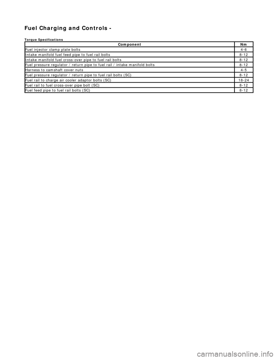
Fuel Ch
arging and Controls -
Torque Specific
ations
Com
ponent
Nm
Fue
l injector cl
amp plate bolts
4-
6
Inta
ke manifold fuel feed pipe to fuel rail bolts
8-
12
Inta
ke manifold fuel cross-over pipe to fuel rail bolts
8-
12
F
uel pressure regulator /
return pipe to fuel rail / intake manifold bolts
8-
12
Harness to
camshaft cover nuts
4-
5
F
uel pressure regulator / return
pipe to fuel rail bolts (SC)
8-
12
F
uel rail to charge air cooler adaptor bolts (SC)
18
-24
F
uel rail to fuel cross-over pipe bolt (SC)
8-
12
F
uel feed pipe to fuel rail bolts (SC)
8-
12
Page 1053 of 2490

Accessory Drive - Acce
ssory
Drive Belt4.0L NA V8 - AJ27/3.2L NA V8 -
AJ26
Re
moval and Installation
Remov
al
Installation
1.
O
pen the engine compartment and fit paintwork protection
sheets.
2. Check the belt wear indicator ma rks to confirm that the drive
belt is / is not within limits.
3. CAUTI
ON: When releasing the
belt tension, never apply
any torque in a clockwise direction to the pulley ce ntre bolt (left
hand thread) as it could subsequently loosen.
Remove the drive belt fro m the accessory drive.
1. Use a spanner e.g. Churchill JD-230 or Snap On XDHM 1415, on the centre bo lt of the belt tensioner
idler pulley, to turn the adju ster assembly to the left,
viewed from the front, against spring tension.
2. Whilst holding the tensioner against spring tension, remove the drive belt from the generator pulley.
Release the tensioner sl owly and remove the
spanner.
пЃ¬D
isconnect the belt from the ot
her pulleys, as necessary.
1. In
stallation is the
reverse of the remova l procedure. Ensure
that the belt is correctly and sq uarely located on each pulley.