lamp JAGUAR X308 1998 2.G Workshop Manual
[x] Cancel search | Manufacturer: JAGUAR, Model Year: 1998, Model line: X308, Model: JAGUAR X308 1998 2.GPages: 2490, PDF Size: 69.81 MB
Page 1919 of 2490
Exterior Lighting - Exterior Lighting
Description and Operation
A multi-function switch located on the left stalk of the steering column switch assembly permits selection of either parking
(side), headlamps, auto-headlamp or off. Selection of a particular mode provides the appropriate input to the body
processor module (BPM).
Where the auto headlamp function is incorporated, a light sensor in the interior rear view mirror monitors ambient light and
provides an input to the BPM. The BPM responds by switching the low beam headlamps on or off as appropriate for the
prevailing light conditions.
The front and rear fog lamp switch is located on the fascia outboard of the steering column.
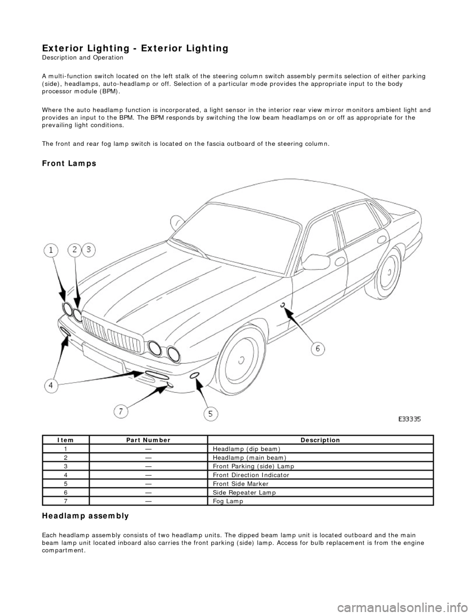
Front Lamps
Headlamp assembly
Each headlamp assembly consists of tw o headlamp units. The dipped beam lamp unit is located outboard and the main
beam lamp unit located inboard also carries the front parking (side) lamp. Access for bulb replacement is from the engine
compartment.
ItemPart NumberDescription
1—Headlamp (dip beam)
2—Headlamp (main beam)
3—Front Parking (side) Lamp
4—Front Direction Indicator
5—Front Side Marker
6—Side Repeater Lamp
7—Fog Lamp
Page 1920 of 2490
Direction indicator and side marker lamps
Each front direction indicator and side marker lamp is retained in the bumper cover by a lug at one end and a spring clip at
the other end. The side marker lamps are not electrically connected for certain markets.
The side repeater lamps are secured by sp ring clips on the lower edge of the lamp unit. In certain markets Jaguar leaper
badges are substituted for side repeater lamps.
Fog lamps
The fog lamps are located in recesses in the front bump er and secured by three screws. The la mps which are not
interchangeable left to right, are accessed from the rear of the bumper.
Operation
All lamps are controlled by the BPM which provides an appropriate output in response to an input received when a selected
switch is operated.
All lamps receive an input direct from th e BPM with the exception of the main be am, dip beam and front fog lamps which
receive an input from the BPM vi a the respective relays and fuses; refer to section 418-01.
Fault analysis must be undertaken using the PDU. Refer to Diagnosis and Testing.
Consult the relevant Electrical Guid e for details of circuit operation.
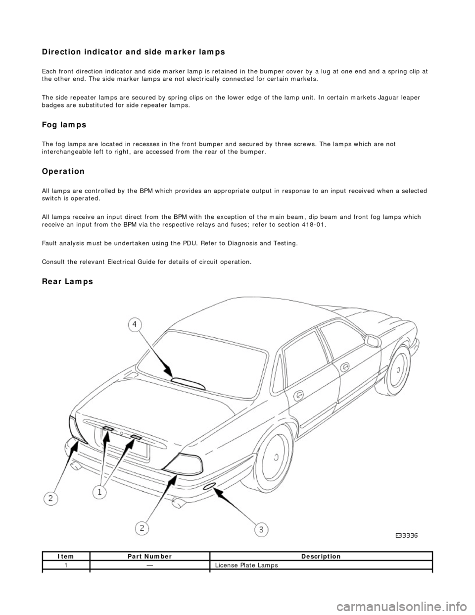
Rear Lamps
ItemPart NumberDescription
1—License Plate Lamps
Page 1921 of 2490
License plate lamps
Each license plate bulb is accessible after removing the relevant lens. The license plate lamps can be accessed following
removal of the trunk lid liner and upper trim finisher.
Rear lamp assembly
Each rear lamp assembly incorporates a stop/tail lamp, a fog lamp, a reversing lamp and a direction indicator lamp. Access
for bulb replacement is from the trunk.
Side markers
Each side marker is retained in the bumper cover by a lug on one end of the unit and a spring clip at the other end. The unit is not electrically connected for all markets.
High mounted stop lamp
The high mounted stop lamp (HMSL) is secu red to studs on the center lower edge of the backlight and provides illumination
using five bulbs.
Operation
All lamps are controlled by the BPM which pr ovides an appropriate output in response to an input received when a selected
switch is operated.
The side marker lamps receive an input from the BPM via relay 3 and fuse F21. The license plate lamps receive an input
from the BPM via relay 3 and fuse F19. The rela y and fuses are located in the trunk fuse-box.
The tail lamps receive an input direct from the BPM.
The stop, reversing and rear fog lamps are controlled by the security and locking module (SLM) which receives inputs via
the SCP network from the BPM.
The HMSL is not controlled by the SLM; it receives input from the brake switch via relay 5 and fuse F8 in the trunk fuse-box.
The BPM and SLM monitor the stop lamps (n ot HMSL) and tail lamps for failure.
Fault analysis must be undertaken using the PDU, refer to Diagnosis and Testing.
Consult the relevant Electrical Guid e for details of circuit operation.
2—Rear Lamp Assembly
3—Rear Side Marker
4—High Mounted Stop Lamp
Page 1922 of 2490

Exterior Lighting - Exterior Lighting
Diagnosis and Testing
Tests Using the Portable Diagnostic Unit
Refer to PDU User Guide
The complexity of the electronics involved with the various Electronic Control Modules and the multiplexed communication
networks, preclude the use of workshop general electrical test equipment. Therefore, reference should be made to the PDU
User Guide for detailed inst ructions on testing the exterior lamps and circuits.
The PDU systematically tests and analyses the lamp assemblies, the bulbs and the electrical connections to them. It should
be noted that the lamps are not wired direct ly to the switches. Actuation of a switch provides an input signal to the Body
Processor which interpre ts the signal as a request to switch output from the Bo dy Processor, either directly or indirectly to a
specific lamp.
Where a fault involving a lamp is indicated by the PDU, befo re replacing the component, some basic diagnostic methods
may be necessary to confirm that connections are good and that wiring is not damaged.
Page 1925 of 2490
Exterior Lighting - Fog Lamp Switch
Removal and Installation
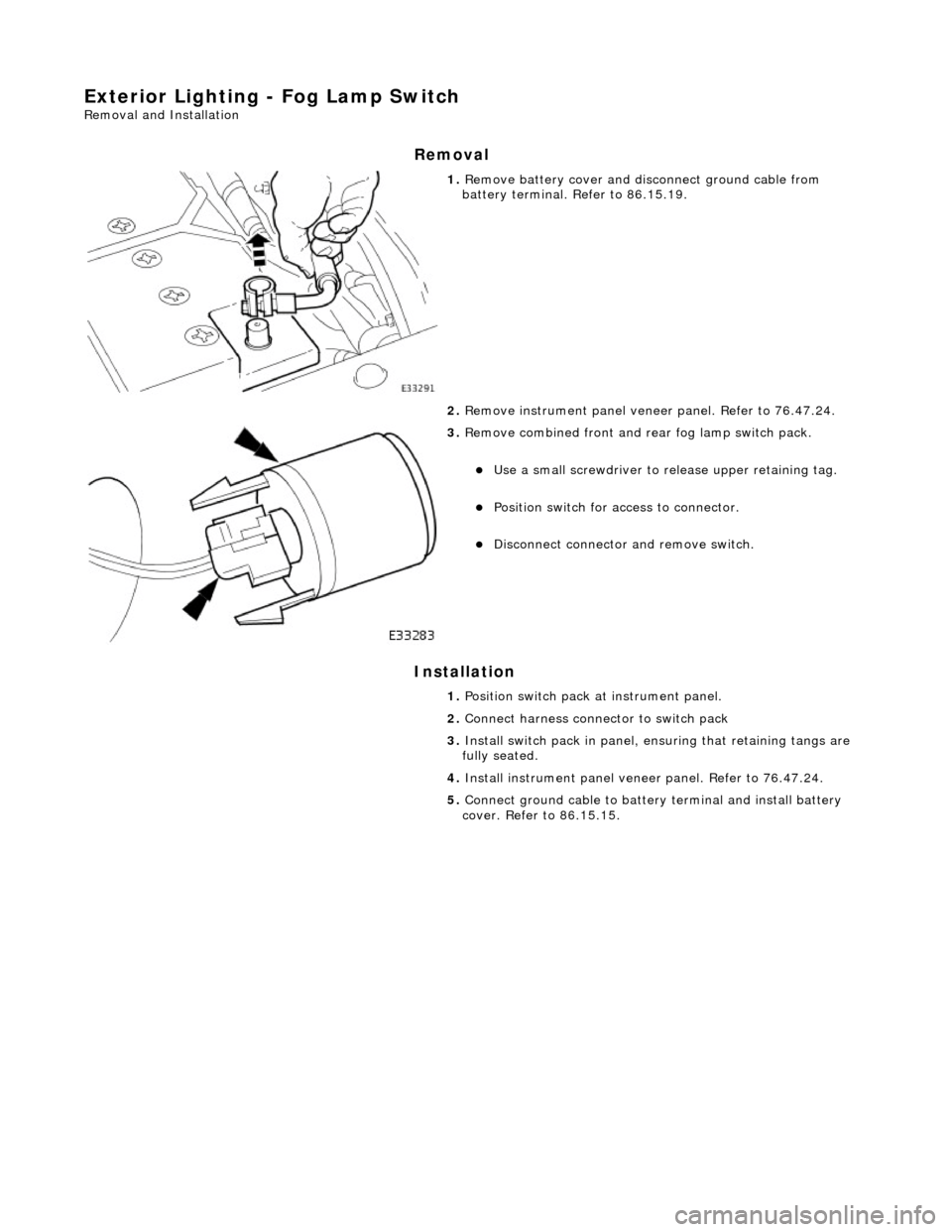
Removal
Installation
1. Remove battery cover and disc onnect ground cable from
battery terminal. Refer to 86.15.19.
2. Remove instrument pa nel veneer panel. Refer to 76.47.24.
3. Remove combined front and rear fog lamp switch pack.
Use a small screwdriver to re lease upper retaining tag.
Position switch for access to connector.
Disconnect connector and remove switch.
1. Position switch pack at instrument panel.
2. Connect harness connector to switch pack
3. Install switch pack in panel, ensuring that retaining tangs are
fully seated.
4. Install instrument panel veneer panel. Refer to 76.47.24.
5. Connect ground cable to batter y terminal and install battery
cover. Refer to 86.15.15.
Page 1926 of 2490
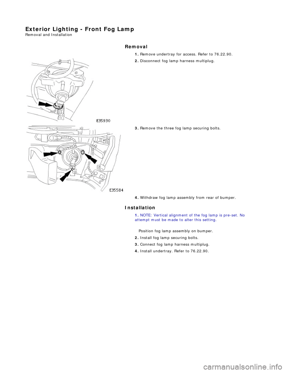
Exterior Lighting - Front Fog Lamp
Removal and Installation
Removal
Installation
1.
Remove undertray for ac cess. Refer to 76.22.90.
2. Disconnect fog lamp harness multiplug.
3. Remove the three fog la mp securing bolts.
4. Withdraw fog lamp assembly from rear of bumper.
1. NOTE: Vertical alignment of the fog lamp is pre-set. No
attempt must be made to alter this setting.
Position fog lamp assembly on bumper.
2. Install fog lamp securing bolts.
3. Connect fog lamp harness multiplug.
4. Install undertray. Refer to 76.22.90.
Page 1927 of 2490
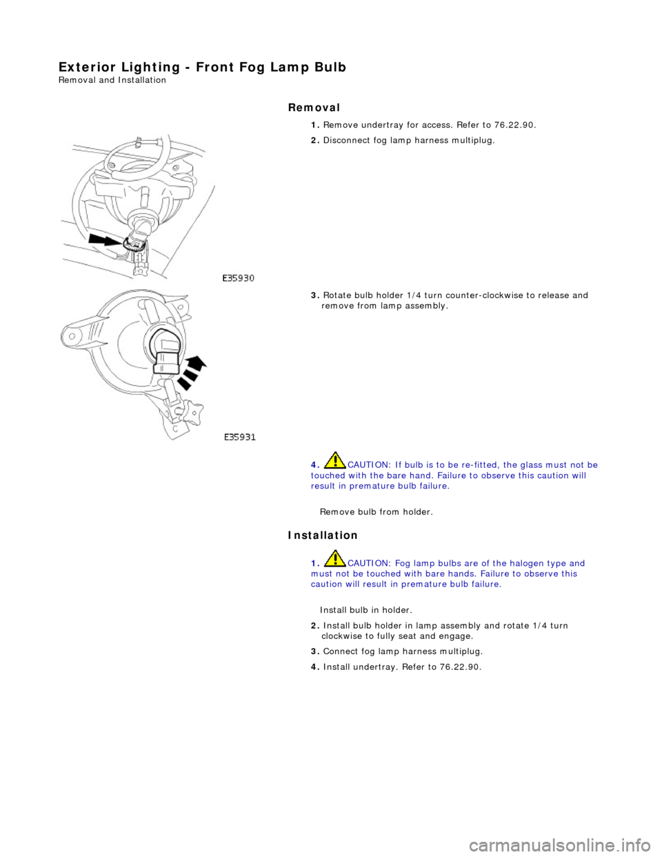
Exterior Lighting - Front Fog Lamp Bulb
Removal and Installation
Removal
Installation
1.
Remove undertray for ac cess. Refer to 76.22.90.
2. Disconnect fog lamp harness multiplug.
3. Rotate bulb holder 1/4 turn counter-clockwise to release and
remove from lamp assembly.
4. CAUTION: If bulb is to be re -fitted, the glass must not be
touched with the bare hand. Failure to observe this caution will
result in premature bulb failure.
Remove bulb from holder.
1. CAUTION: Fog lamp bulbs are of the halogen type and
must not be touched with bare hands. Failure to observe this
caution will result in premature bulb failure.
Install bulb in holder.
2. Install bulb holder in lamp assembly and rotate 1/4 turn
clockwise to fully seat and engage.
3. Connect fog lamp harness multiplug.
4. Install undertray. Refer to 76.22.90.
Page 1928 of 2490
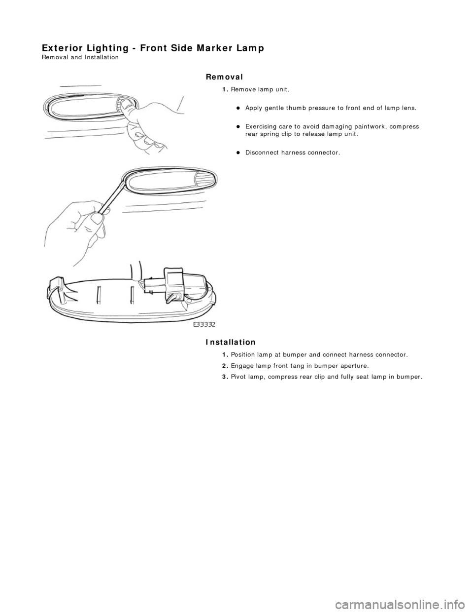
Exterior Lighting - Front Side Marker Lamp
Removal and Installation
Removal
Installation
1. Remove lamp unit.
Apply gentle thumb pressure to front end of lamp lens.
Exercising care to avoid damaging paintwork, compress
rear spring clip to release lamp unit.
Disconnect harness connector.
1. Position lamp at bumper an d connect harness connector.
2. Engage lamp front tang in bumper aperture.
3. Pivot lamp, compress rear clip and fully seat lamp in bumper.
Page 1929 of 2490

Exterior Lighting - Front Side Marker Lamp Bulb
Removal and Installation
Removal
1. Applying firm hand pressure to front end, pivot lamp assembly
for access to rear end.
2. Exercising care to avoid dama ging paintwork, use a small
screwdriver at rear end of lamp, to press and release retaining
tang.
3. Withdraw lamp from bumper for access and disconnect harness multiplug.
4. Rotate bulb holder 1/4 turn counter-clockwise to release it
from lamp assembly.
5. Withdraw bulb from holder.
Page 1930 of 2490

Installation
1. Install bulb in holder.
2. Install bulb and bulb holder in lamp assembly and rotate 1/4
turn clockwise to seat and retain.
3. Position direction lamp at bumper aperture and connect
harness multiplug.
4. Engage front end tang of lamp in bumper aperture.
5. Pivot lamp assembly and firmly seat rear retaining clip in
bumper aperture.