body JAGUAR X308 1998 2.G Workshop Manual
[x] Cancel search | Manufacturer: JAGUAR, Model Year: 1998, Model line: X308, Model: JAGUAR X308 1998 2.GPages: 2490, PDF Size: 69.81 MB
Page 13 of 2490

Removal and Installation
Fuel Injection Supply Manifo ld LH
(19.60.05)
Fuel Injection Supply Manifold RH (19.60.04)
Fuel Injection Supply Manifold Pipe (19.41.04)
Fuel Injector Vehicles Without: Supercharger (18.10.01)
Fuel Injector Vehicles With: Supercharger (18.10.01)
Fuel Injectors Vehicles With: Supercharger (18.10.02)
Throttle Body (19.70.04)
Throttle Body Gasket (19.70.07)
303‐05: Accessory Drive
Descriptio
n and Operation
Accessory Drive
Removal and Installation
Accessory Drive Belt (12.10.40) ‐ 3.2L NA V8 ‐ AJ26/4.0L NA V8 ‐ AJ27
Accessory Drive Belt (12.10.40) ‐ 4.0L SC V8 ‐ AJ26
Accessory Drive Belt Idler Pulley (12.10.43) ‐ 3.2L NA V8 ‐ AJ26/4.0L NA V8 ‐ AJ27
Accessory Drive Belt Idler Pulle
y (12.10.43) ‐ 4.0L SC V8 ‐ AJ26
Accessory Drive Belt Tensioner (12.10.41) ‐ 3.2L NA V8 ‐ AJ26/4.0L NA V8 ‐ AJ27
Accessory Drive Belt Tensioner (12.10.41) ‐ 4.0L SC V8 ‐ AJ26
Supercharger Belt (18.50.08)
Supercharger Belt Idler Pulley (18.50.09)
Supercharger Belt Tensioner (18.50.24)
303‐06: Starting System
Description and Operati
on
Starting System
Diagnosis and Testing
Starting System
Inspection and Verification
Diagnostic Trouble Code (DTC) Index
Pinpoint Tests
Removal and Installation
Starter Motor (86.60.01)
Page 15 of 2490

Superchar
ger
Outlet Pipe (18.50.16)
Supercharger Outlet Pipe Gasket (18.50.17)
Throttle Body Elbow (19.70.28)
Throttle Body Elbow Gasket (19.70.29)
303‐13: Evaporative Emissions
Diagnosis and Testing
Evaporative Emissions
Preliminary
Inspection
Diagnostic
Drive Cycles
Diagnostic
Trouble Code (DTC) index/Symptom Chart
Pinpoint
Tests
Removal
and Installation
Evaporative
Emission Canister (17.15.13)
Evaporative
Emission Canister Purge Valve (17.15.30)
Fuel
Tank Press
ure Sensor (19.55.31)
Fuel
Vapor Vent Valve Housing (19.55.24)
Fuel
Vapor Vent Valve Housing Seal (19.55.25)
303
‐14: Electronic Engine Controls
Description
and
Diagnosis
and Testing
Electronic
Engine Con
trols
Inspection
and Verification
Driver
Information Chart
Default
mode Definitions
Diagnostic
Trouble Code (DTC) Index
Pinpoint
Tests
Removal
and Installation
Catalyst
Monitor Sensor LH (18.30.81)
Catalyst
Monitor Sensor RH (18.30.80)
Heated Oxygen Sensor (HO2S) LH (18.30.79)
Heated Oxygen Sensor (HO2S) RH (18.30.78)
Camshaft
Position
Sen s
or
ECM
Position
Sensor
Crankshaft
Removal
Engine
Coolant Temperature
Sensor
Operation
Intake Air Temperature (IAT) Sensor (18.
30.52)
Page 16 of 2490

Knock Sensor (KS) RH (18.30.93)
Variable Camshaft Timing (VCT) Oil Co ntrol
Solenoid (18.30.90)
307: Automatic Transmission/Transaxle
307‐01A : Automatic Transmission/Transaxle ‐ 3.2L NA V8 ‐ AJ26/4.0L NA V8 ‐ AJ27
Specification
Description and Operation
Transmission Description
Diagnosis and Testing
Diagnostic Strategy
General Procedures
Transmission Fluid Drain and Refill (44.24.02)
In‐Ve
hicle Repair
Electronic Pressure Control (EPC) Solenoid (44.15.51)
Extension Housing Seal (44.20.18)
Extension Housing O ‐Ring Seal (44.20.19)
Main Control Valve Body (44.40.01)
Output Shaft Speed (OSS) Sensor (44.15.41)
Shift Solenoids (SS) (44.15.50)
Transmission Control Module (TCM) (44.15.32)
Transmission Fluid Filter (44.24.07)
Transmission Fl
uid Pan (44.24.04)
Transmission Fluid Pan Gasket (44.24.05)
Transmission Internal Wiring Harness (44.15.35)
Transmission Internal Wiring Harness Electrical Connector O‐Ring Seals
(44.24.20)
Transmission Range (TR) Sensor
Transmission Support Insulator (12.45.04)
Turbine Shaft Speed (TSS) Sensor (44.15.40)
Removal
Transmission (44.20.01)
Disassembly and Assembly of Subassemblies
Input Sh
aft Seal (44.32.07)
Torque Converter (44.17.07)
Installation
Transmission (44.20.01)
Mass
Airflow
Sen s
or
Knock
Sensor
(KS)
LH
(18.30.92)
Page 17 of 2490

307‐01B : A u
tomatic
Transmission/Transaxle ‐ 4.0L SC V8 ‐ AJ26
Specification
Description and Operation
Transmission Description
Diagnosis and Testing
Diagnostic Strategy
General Procedures
Transmission Fluid Drain and Refill (44.24.02)
In‐Vehicle Repair
Extension Housing Seal (44.20.18)
Main Control Valve Body (44.40.01)
Transmission Fluid Filter (44.24.07)
Transmission Fl
uid Pan Gasket (44.24.05)
Transmission Internal Wiring Harness Electrical Connector O‐Ring Seals
(44.24.20)
Transmission Support Insulator (12.45.04)
Removal
Transmission (44.20.01)
Disassembly and Assembly of Subassemblies
Input Shaft Seal (44.32.07)
Torque Converter (44.17.07)
Installation
Transmission (44.20.01)
307‐02A : Transmission/Transaxle Cooling ‐ 3.2L NA V8 ‐ AJ26/4.0L NA V8 ‐ AJ
27
Description and Operation
Transmission Cooling
307‐02B : Transmission/Transaxle Cooling ‐ 4.0L SC V8 ‐ AJ26
Description and Operation
Transmission Cooling
307‐05A : Automatic Transmission/Transaxle External Controls ‐ 3.2L NA V8 –
AJ26/4.0L NA V8 ‐ AJ27
Description and Operation
External Controls
Page 27 of 2490

419:
Electronic Featu r
e
Group
419
‐10:
Multifunction Electronic Modules
Removal
and Installation
Driver
Seat Module (DSM) (86.75.28)
5: Body and Paint
501: Body and Paint
501‐00: Body System ‐ Gen
eral Information
Specification
Description and Operation
Body
501‐02: Front End Body Panels
Description and Operation
Front End Body Panels
Removal and Installation
Cowl Panel Grille (76.10.01) (76.43.39)
Driver Side Bulkhead Cover (76.11.34)
Passenger Side Bulkhead Cover (76.11.33)
Radiator Grille Opening Panel (76.10.06)
Radiator Grille Ope
ning Panel Reinforcement (76.11.24)
Radiator Splash Shield (76.22.90)
501‐03: Body Closures
Description and Operation
Body Closures
General Procedures
Hood Alignment (76.16.02)
Diagnosi
s
and Testing
(FDM)
Front
Door Module
(86.80.34)
Rear
(RDM)
Door
Module
Page 34 of 2490

501‐20B : Supp l
emental
Restraint System
Specification
Description and Operation
Air Bag Supplemental Restraint System (SRS)
Removal and Installation
Air Bag Control Module (76.73.41)
Driver Air Bag Module (76.73.39)
Passenger Air Bag Module (76.73.37)
Side Air Bag Module (76.73.47)
Side Impact Sensor (76.73.53)
501‐25: Body Repairs ‐ Genera
l Information
Description and Operation
Body Repairs
502: Frame and Mounting
502‐00: Uni ‐Body, Subframe and Mounting System
Removal and Installation
Front Axle Crossmember
Front Axle Crossmember Front Bushing (60.35.24)
Front Axle Crossmember Front Bushing Heat Shield (60.35.37)
Front Axle Crossmember Rear Bushing (
60.35.26)
Rear Axle Crossmember (64.25.16)
Rear Axle Crossmember Bushing (64.25.02)
Page 35 of 2490

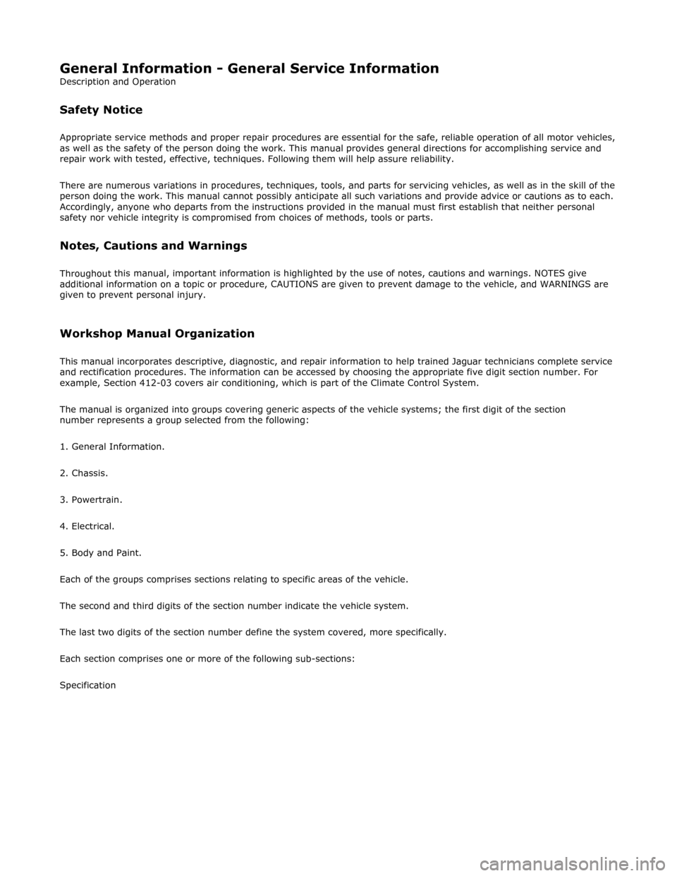
General Infor
mation - Gene
ral Service Information
Description an
d Operation
Safety Notice
Appropri
ate service me
thods and proper repair procedures are essential for the safe, reliable operation of all motor vehicles,
as well as the safety of the person do ing the work. This manual provides genera l directions for accomplishing service and
repair work with tested, effect ive, techniques. Following them will help assure reliability.
There are numerous variations in procedures, techniques, tools, and parts for servicing vehicles, as well as in the skill of the
person doing the work. This manual cannot possibly anticipate all such variations and provide advice or cautions as to each.
Accordingly, anyone who depart s from the instructions provided in the manua l must first establish that neither personal
safety nor vehicle integrity is compromised from choices of methods, tools or parts.
Notes, Ca
utions and Warnings
Throughout
this manual, important inform
ation is highlighted by the use of notes, cautions and warnings. NOTES give
additional information on a topic or proc edure, CAUTIONS are given to prevent da mage to the vehicle, and WARNINGS are
given to prevent personal injury.
Worksh
op Manual Organization
This
manual incorporates descript
ive, diagnostic, and repair information to help trained Jaguar technicians complete service
and rectification procedures. The informat ion can be accessed by choosing the appropriate five digit section number. For
example, Section 412-03 covers air conditioning , which is part of the Climate Control System.
The manual is organized into groups covering generic aspects of the vehicle systems; the first digit of the section
number represents a group se lected from the following:
1. General Information.
2. Chassis.
3. Powertrain.
4. Electrical.
5. Body and Paint.
Each of the groups comprises sections re lating to specific areas of the vehicle.
The second and third digits of the section number indicate the vehicle system.
The last two digits of the se ction number define the system covered, more specifically.
Each section comprises one or more of the following sub-sections:
Specification
Page 42 of 2490

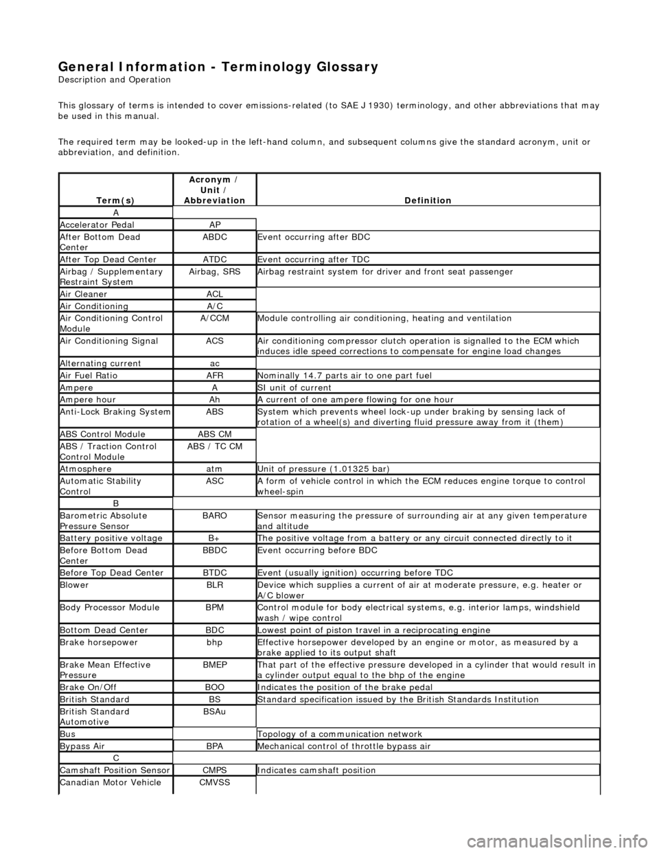
General Information - Terminology Glossary
Description an
d Operation
This glossary of terms is intended to cover emissions-related (to SAE J 1930) term inology, and other abbreviations that may
be used in this manual.
The required term may be looked-up in th e left-hand column, and subsequent columns give the standard acronym, unit or
abbreviation, and definition.
Te rm
(s)
Acr
ony
m /
Unit /
Abbreviation
De fi
nition
A
Accel
e
rator Pedal
AP
Af
ter Botto
m Dead
Center
ABDCEvent occurri ng after
BDC
Af
ter Top Dead CenterATDCEvent occurri ng after
TDC
Ai
rbag /
Supplementary
Restraint System
Airbag, SRSAi rbag restraint system for
dr
iver and front seat passenger
Air Cleane rACL
Air ConditioningA/C
Air Conditioning Con t
rol
Module
A/CCMModule c
ontrolling air conditioning, heating and ventilation
Air Conditioning SignalACSA
i
r conditioning compressor clutch operation is signalled to the ECM which
induces idle speed corrections to co mpensate for engine load changes
Alternating cu
rrent
ac
Ai
r Fuel R
atio
AFRN
omi
nally 14.7 parts air to one part fuel
Ampe
reASI unit of current
Ampere hourAhA current of one ampere
fl
owing for one hour
Anti-Lock Braking SystemABSS
y
stem which prevents wheel lock-up
under braking by sensing lack of
rotation of a wheel(s) and divertin g fluid pressure away from it (them)
ABS Control Mo
dule
ABS CM
ABS /
T
raction Control
Control Module
ABS / T
C CM
Atmosph
e
re
atmU
n
it of pressure (1.01325 bar)
Au
to
matic Stability
Control
ASCA form of vehicle
control
in which the ECM reduces en gine torque to control
wheel-spin
B
Baro me
tric Absolute
Pressure Sensor
BAR OSensor measuring the pressure of surr ou
nding air at any given temperature
and altitude
Bat t
ery positive voltage
B+The posi
ti
ve voltage from a battery or
any circuit connected directly to it
Before Bottom Dead
CenterBBDCEvent occurri ng before BD
C
Before Top Dead
Center
BTD
CEvent (usual ly
ignition) occurring before TDC
Blowe
rBLRDe
vice which supplies a current of air at
moderate pressure, e.g. heater or
A/C blower
Body Processor M
odule
BPMControl modu
le
for body electrical systems, e.g. interior lamps, windshield
wash / wipe control
Bott om D
ead Center
BD
CLowest poin t of piston
travel in a reciprocating engine
Brake hors
epowe
r
bhpEffecti
ve horsepower devel
oped by an
engine or motor, as measured by a
brake applied to its output shaft
Brake Mean Effective
Pres sureBME PThat p
art of the effective
pressure developed in a cyli nder that would result in
a cylinder output equal to the bhp of the engine
Brake On/ O
ff
BOOIn
dic
ates the position of the brake pedal
Br
it
ish Standard
BSStan
dar
d specification issued by the British Standards Institution
Br
it
ish Standard
Automotive
BSAu
BusTopology of a commu n
ication network
Bypass
AirBPAMechanica l
control of throttle bypass air
C
Camshaft Posit
i
on Sensor
CMPSIndi
cat
es camshaft position
Canadian Motor
V
ehicle
CMVSS
Page 43 of 2490

Safety Standard
Canister PurgeCANPControls pu
rging of the EVAP canister
Carbon dioxideCO2Colorless gas with
a density of a
pproximately 1.5 ti mes that of air
Carbon mon
oxide
COPoi
sonous gas produced as the re
sult of incomplete combustion
Case G
round
CSE GNDControl modu
le casing ground
Catal
ytic converter
In
-line exhaust system device used to reduce the level of engine exhaust
emissions
Ce
lsius
CSI ter
m for the Centigrade scale, with
freezing point at zero and boiling point
at 100°
Central
Processor Unit
CPUTh
e section of a computer that contai
ns the arithmetic, logic and control
circuits. It performs arithm etic operations, controls instruction processing, and
provides timing signals and other housekeeping operations
Cl
osed Loop
CL
Cl
osed Loop System
CLSControl
system with one
or more feedback loops
Col
umn/Mirror Control
Module
C/MC
M
Control ModuleCMA
self-contained group of electrical/electronic components, designed as a
single replaceable un it, and controlling one or more processes
Controll
er Area Network
CANA
communication system which allows control modules to be linked together
in a network.
Crankshaft Posi
tion
Sensor
CKPSGenerates crankshaft positi on informa
tion in conjunct
ion with the CKPTR (also
generates speed information in certain applications)
Crankshaft Posi
tion
Timing Ring
CKPT
R
Toothe
d ring which
triggers the CKPS
Crankcase Ventila
tion
System
CVSys
tem which scavenges camshaft cover and crankcase emissions and feeds
them into the inlet manifold
Cubic ce nt
imeter
cm
3
Curb weightWe
ight of vehicle with fuel, lubrican
ts and coolant, but excluding driver,
passengers or payload
D
Dat
a Link Connector
DLCConne
ctor providing access and/or control of the vehicle information,
operating conditions, and diagnostic information
De
gree
deg, °Angle or tempe
rature
D
epartment of
Transportation (US)
DO
T
D
epartment of Transport
(UK)
DTp
De
utsche In
stitut für
Normung
DINGerman stand
ards regulation body
Di
agnostic Module
DMSuppl
emental Restraint System (non-c
ontrolling) module for diagnostics
overview
Di
agnostic Test Mode
DTMA le
vel of capability in an OBD system.
May include different functional states
to observe signals, a base level to re ad DTCs, a monitor level which includes
information on signal levels, bi-directional control with on /off board aids, and
the ability to interface with remote diagnosis
Diagnostic Trouble CodeDTCAn al
pha/numeric identifier for a fault
condition identified by the On-Board
Diagnostic (OBD) system
D
ial test indicator
DTIA mechan
ical measuring
instrument, with a rotary indicating pointer
connected to a linear operating probe
D
ifferential pressure
Pressure di
fference betwee
n two regions e.g. between intake manifold and
atmospheric pressures
D
ifferential Pressure
Feedback EGR
DP
FE
An
EGR system that monito
rs differential EGR pressure across a remote orifice
to control EGR flow
D
irect current
dcCurrent which f
lows in on
e direction only, though it may have appreciable
pulsations in its magnitude
Du
al linear switch
DLSJ
-gate switch connected to the TCM on SC vehicles
E
EGR
Temperature EGRT
Sensor
EGRTSens
ing EGR function based on temperature change
EGR Vacu
um Regulator
EVRControls EGR
flow by changi
ng vacuum to the EGR valve
EGR Valve
Position
EVPAn EGR
system that direct
ly monitors EGR valve position to control EGR flow
Electrically E
rasable
Programmable Read-Only
Memory
EEP
ROM
Page 47 of 2490

Mem
ory
Pulse Width ModulationPW
M
A
method of control in an electronic co
ntrol system in which the duration of
pulses in a pulse train is proportional to the amplitude of the modulating
signal
R
Ran
dom Access Memory
RAMF
ast access memory store which is accessible for entry or extraction of data
Re
ad-Only Memory
RO
M
F
ast access memory in which data
is fixed and may not be changed
Re
servoir
RESContaine
r, usually for oils,
coolants or hydraulic fluids
Re
turn
RTNA
dedicated sensor ground circuit
R
evolutions Per Minute
RP
M
Shaft speed o
f a device, us
ually an engine or motor
R
ight-hand
RH
Right-hand drive veh
icle
RHD
S
Scan T
ool
STDe
vice that interfaces with and comm
unicates information on a data link
Se
at Control Module
SCMModule
controlling the seat motor systems (not electric raise/lower-only
seats)
Secon
dary Air
Air pro
vided to the exhaust system
Secon
dary Air Injection
AIRSy
stem used for a period of time each
time the engine is started, unless
certain temperature criter ia are met. Pumps air directly into the exhaust
system which generates extra heat and reduces the time taken for the
catalytic converters to reach operating temperature
Secon
dary Air Injection
Bypass
AIRBVents secon
dary air to atmosphere
Secon
dary Air Injection
Check Valve
AIRCValve wh
ich prevents back-flow of exhaust gas to the AIR system when the
system is inoperative
Secon
dary Air Injection
Diverter
AIRDD
iverts secondary air to either
the catalyst or exhaust manifold
Secon
dary Air Injection
Magnetic Clutch
AIRP
C
Clu
tch mounted on the AIRP drive shaft
Secon
dary Air Injection
Pump
AIRPMe
chanically driven rotary vane
pump, driven through the AIRPC
Secon
dary Air Injection
Relay
AIRRCont
rols the injection of air into the exhaust system
Secon
dary Air Injection
Switchin
g Va
lve
AIRSV
acuum operated valve backing-up the AIRC
Secu
rity and Locking
Control Module
SLCMModul
e controlling the vehicle's security and closure-locking functions
SensorSGeneri
c name for a device
that senses either the absolute value or a change
in a physical quantity su ch as temperature, pressure or flow rate, and
converts that change into an electrical quantity signal
Servic
e Repair Operation
(number)
SRONu
mber generated by Jaguar Methods
and Techniques system which relates
to the time allowed to complete a repair operation. Further information on the
system can be found in the separate Jaguar Publications (for each model
range) entitled 'Repair Operation Times'
Shif
t signal
SDA
shift process signal to the TCM on SC vehicles
Shif
t Solenoid
SSControls shi
fting in an automatic transmission
Si
gnal return
SIG RTN
Slidin
g Roof Control
Module
SRCM
Society of Automotive
Engineers
SAE
Speed
Control Control
Module
SCCMModule con
trolling Speed Control System
Square c
entimeter
cm
2
Stan
dard
std
Stan
dard Corporate
Protocol
SCPA
high-speed, serial communications system linking all body system control
modules. Control messages and data ar e passed between modules at up to
786 messages per second
SuperchargerSCAn in
take system which utilizes a supercharger (mechanically driven device
that pressurizes intake air, thereby in creasing density of charge air and the
consequent power output from a given displacement)
Supercharger
Bypass
SCB
SwitchSW
T