body JAGUAR X308 1998 2.G Service Manual
[x] Cancel search | Manufacturer: JAGUAR, Model Year: 1998, Model line: X308, Model: JAGUAR X308 1998 2.GPages: 2490, PDF Size: 69.81 MB
Page 346 of 2490

2.
Remove paper backing from pads to reveal adhesive
shim. Install brake pads, insert clip located on back of
inner pad into caliper piston.
3. Inst al
l caliper housing to caliper carrier.
Align hou
s
ing to carrier.
1. Install and tighten guide pins to 25-30 Nm.
2. Install dust covers.
3. Install anti-rattle spring.
4. NOTE : Th
e brake hose must only be installed with the vehicle's
body supported and the suspension hanging.
Install and tighten brake hose to caliper housing to 10-14 Nm.
5. NO
TE: Make sure the brake
hose does not twist when
tightening the hose lock-nut.
Connect brake hose to brake tube.
1. Position hose thread through bracket.
2. Install and tighten locking nut. Refer to Specifications, section 206-03.
3. Install and tighten brake- tube union nut. Refer to
Specifications, section 206-03.
6. Remove special tool from brake pedal.
7. Fit wheels. Refer to section 204-04.
8. NOTE: Make sure the brake hose is routed correctly.
Remove stands and lower vehicl e. Refer to section 100-02.
9. Bleed brake hydraulic system. See operation 70.25.03.
Page 350 of 2490

2.
Po
sition anti-rattle spring.
3. Install pins.
4. Install 'R' clips.
3. CAUTIO
N: The brake hose must
only be installed with the
vehicle's body supported and the suspension hanging.
Install brake hose to caliper.
Remove plugs f rom caliper and hose.
Instal
l new sealing washers.
Install and tigh
ten un
ion bolt to 22-26 Nm.
4.
NO
TE: Make sure the brake
hose does not twist when
tightening the hose lock-nut.
Connect brake hose to brake tube. 1. Position hose thread through bracket.
2. Install and tighten locking nut. Refer to Specifications, section 206-03.
3. Install and tighten brake- tube union nut. Refer to
Specifications, section 206-03.
5. Remove special tool from brake pedal.
6. Fit wheels. Refer to operation 74.20.05.
7. NOTE: Make sure the brake hose is routed correctly.
Remove stands and lower vehicl e. Refer to section 100-02.
8. Bleed brake hydraulic system. See operation 70.25.06.
Page 364 of 2490
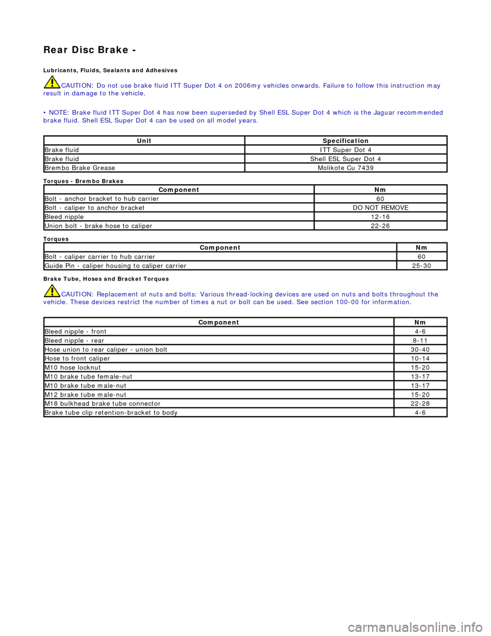
Rear Disc Brake -
Lubric
ants, Fluids, Sealants and Adhesives
CAUTI
O
N: Do not use brake fluid ITT Supe
r Dot 4 on 2006my vehicles onwards. Fa ilure to follow this instruction may
result in damage to the vehicle.
• NOTE: Brake fluid ITT Super Dot 4 has now been superseded by Shell ESL Super Dot 4 which is the Jaguar recommended
brake fluid. Shell ESL Super Dot 4 can be used on all model years.
Torques
- Brembo Brakes
Torques
Brake Tube, Hoses and Bracket Torques
CAUTIO
N: Replacement of
nuts and bolts: Various thread-locking devices are used on nuts and bolts throughout the
vehicle. These devices restrict the number of times a nut or bolt can be used. See section 100-00 for information.
UnitS p
ecification
Brake flu
i
d
ITT Supe
r Dot 4
Brake flui
d
Shell E
SL Supe
r Dot 4
Brem
bo Brake G
rease
Mol
i
kote Cu 7439
Com
p
onent
Nm
Bol
t
- anchor bracket to hub carrier
60
B
o
lt - caliper to anchor bracket
DO
N
OT REMOVE
Bleed n
i
pple
12
-16
Un
ion bolt - brake hose to caliper
22
-26
Com p
onent
Nm
Bol
t
- caliper carrier to hub carrier
60
Guide
Pi
n - caliper housing to caliper carrier
25
-30
Comp
onent
Nm
Bleed ni
pple - front
4-6
Bleed ni
pple - rear
8-11
Hose union to rear cal
i
per - union bolt
30
-40
Hose to fr ont cal
iper
10
-14
M1 0 h
ose locknut
15
-20
M10 brake
tube female-nut
13
-17
M10 brake
tube male-nut
13
-17
M12 brake
tube male-nut
15
-20
M18 bu
lkhead brake tube connector
22
-28
Brake tube clip retention -
bracket to body
4-
6
Page 374 of 2490

In
stallation
11
. Remove brake
dust and clean
mating surfaces. See Warning
above.
1. Inst al
l caliper to hub carrier.
Install and tigh
ten bolts to 6
0 Nm.
2. CAUTI O
NS:
Retracting the caliper piston may cause the fluid reservoir
to over-flow. Remove brake flui d spillage immediately from paint
work with clean water.
Note the condition of the pi ns and replace if necessary.
Install brake pads. Refer to 70 .40.09 for anti-squeal grease
application.
Sl owly
retract caliper pistons.
1. Install pads.
2. Position anti-rattle spring.
3. Install pins - make sure pin collets are fully engaged
into caliper.
3. CAUTI O
NS:
The brake hose must only be installed with the vehicle's
body supported and the suspension hanging.
It is important that the brake hose is aligned correctly when
Page 390 of 2490
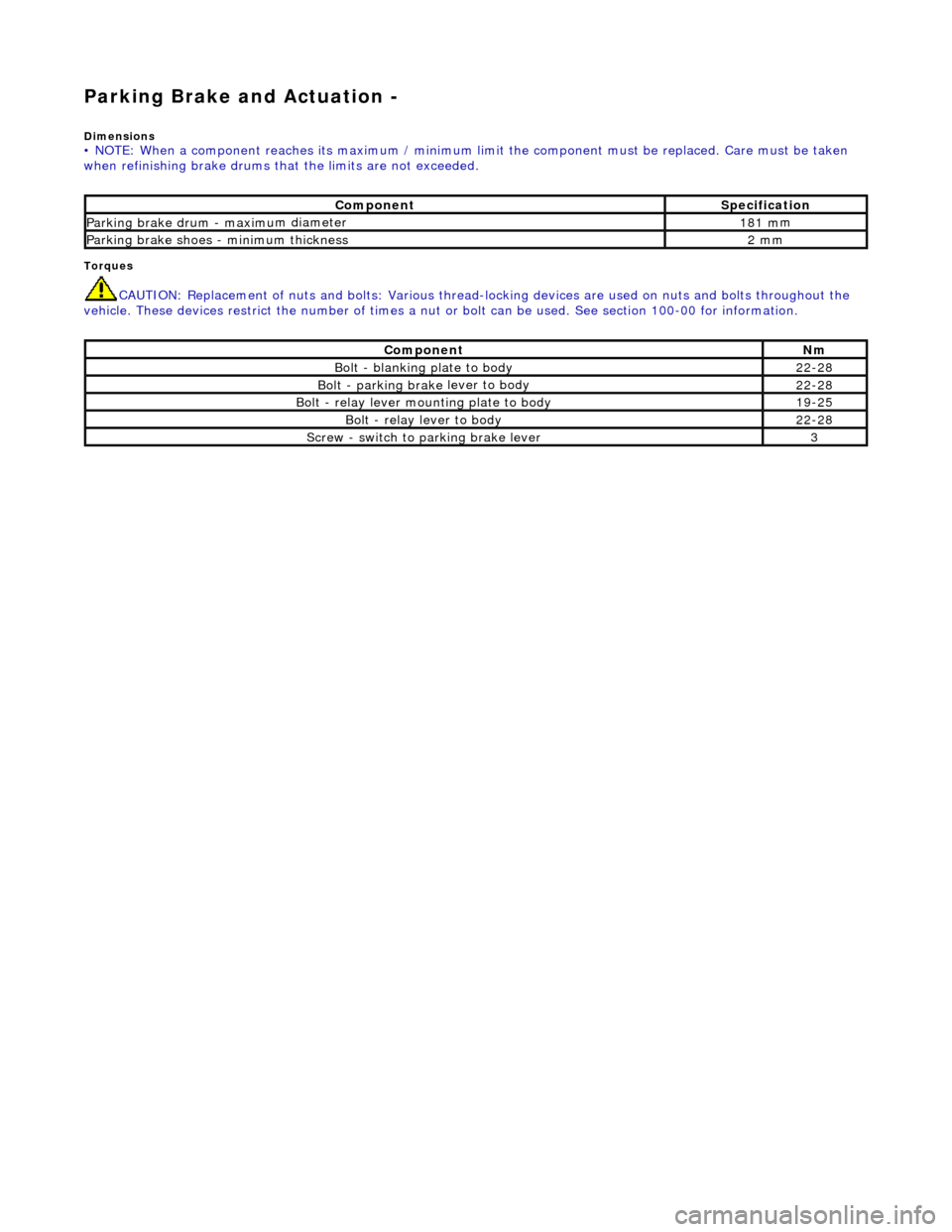
Parking Brake and Actuation -
Dim
ensions
• NO
TE: When a component reaches its maximum / minimum limit the component must be replaced. Care must be taken
when refinishing brake drums that the limits are not exceeded.
Torq ues
CAUTI
O
N: Replacement of
nuts and bolts: Various thread-locking devices are used on nuts and bolts throughout the
vehicle. These devices restrict the number of times a nut or bolt can be used. See section 100-00 for information.
Com p
onent
S
p
ecification
Parkin
g brake drum - maximu
m diameter
1
81 m
m
Parkin
g brake sh
oes - minimum thickness
2 m
m
Com p
onent
Nm
Bolt - blan
k
ing plate to body
22
-28
Bolt - park ing brake
lever to body
22
-28
Bolt - r
elay lever mounting plate to body
19
-25
Bo lt
- relay lever to body
22
-28
Screw - switch to parking brake lever3
Page 405 of 2490

Hydraulic B
rake Actuation -
Lubri
cants, Fluids, Sealants and Adhesives
Torques
Torques - Brembo Brakes
Brake Tube, Hoses and Bracket Torques
CAUTI
ON: Replacement of
nuts and bolts: Various thread-locking devices are used on nuts and bolts throughout the
vehicle. These devices restrict the number of times a nut or bolt can be used. See section 100-00 for information.
UnitS
pecification
Brake flu
id
ITT Supe
r Dot 4
Com
ponent
Nm
N
ut - master cylinder to brake booster
21
-29
Nu
t - brake pedal pivot-pin to pedal housing
17
-23
Nu
t - brake switch to pedal housing
3
Nu
t - pedal housing to body
15
-20
Nu
t - brake booster to pedal housing
22
-28
Com
ponent
Nm
Bleed n
ipple
12
-16
U
nion bolt - brake hose to caliper
22
-26
Com
ponent
Nm
Bleed n
ipple - front
4-
6
Bleed n
ipple - rear
8-1
1
Hose to fr
ont caliper
10
-14
U
nion to rear caliper - union bolt
30
-40
M1
0 hose locknut
15
-20
M10
brake tube female-nut
13
-17
M10
brake tube male-nut
13
-17
M12
brake tube male-nut
15
-20
M18
brake tube male-nut
22
-28
Brake tube clip retention
-bracket to body
4-
6
Page 421 of 2490
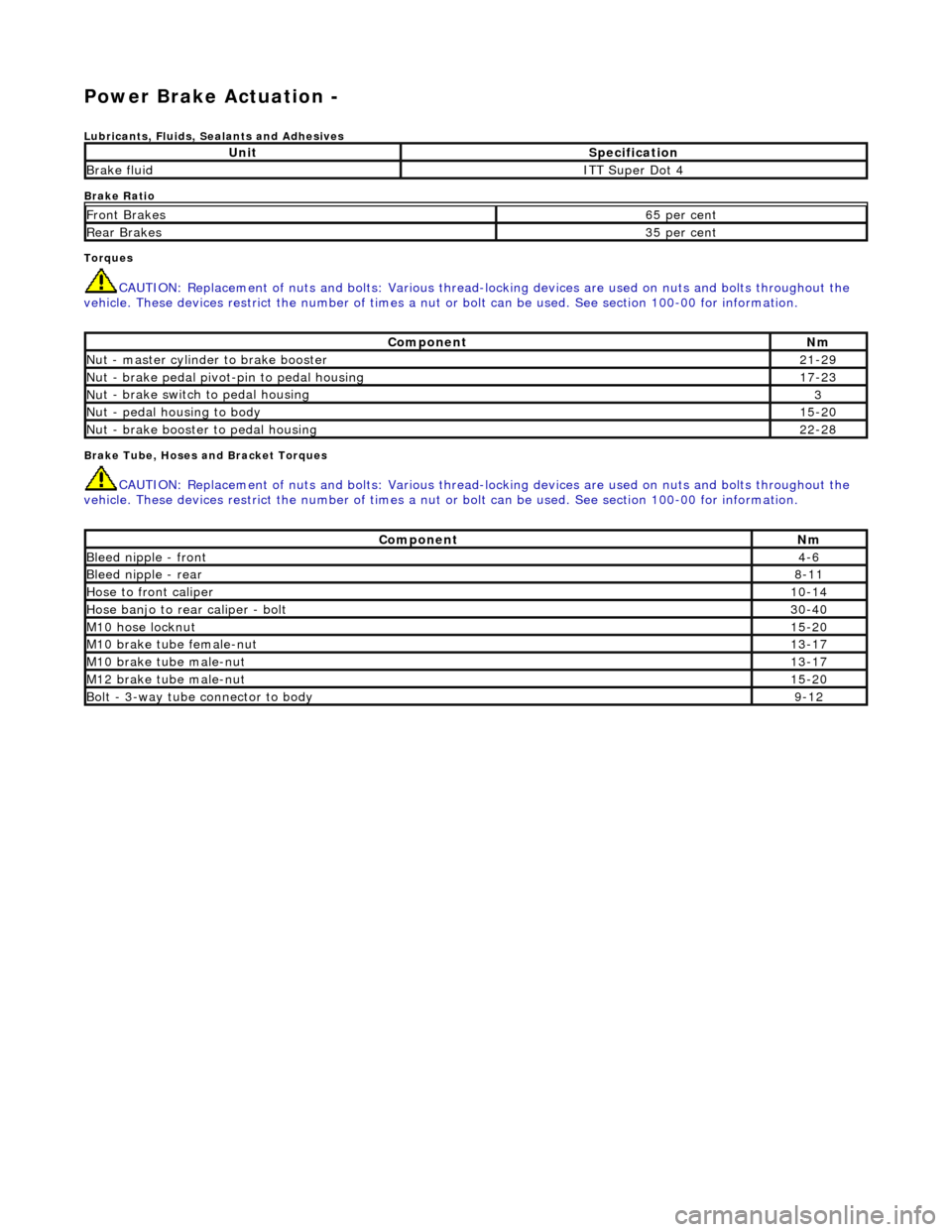
Power Brake Actuation -
Lubri
cants, Fluids, Sealants and Adhesives
Brake Ratio
Torques
CAUTI
ON: Replacement of
nuts and bolts: Various thread-locking devices are used on nuts and bolts throughout the
vehicle. These devices restrict the number of times a nut or bolt can be used. See section 100-00 for information.
B
rake Tube, Hoses and Bracket Torques
CAUTI
ON: Replacement of
nuts and bolts: Various thread-locking devices are used on nuts and bolts throughout the
vehicle. These devices restrict the number of times a nut or bolt can be used. See section 100-00 for information.
UnitS
pecification
Brake flu
id
ITT Supe
r Dot 4
Fr
ont Brakes
6
5 per cent
Rear B
rakes
3
5 per cent
Com
ponent
Nm
N
ut - master cylinder to brake booster
21
-29
Nu
t - brake pedal pivot-pin to pedal housing
17
-23
Nu
t - brake switch to pedal housing
3
Nu
t - pedal housing to body
15
-20
Nu
t - brake booster to pedal housing
22
-28
Com
ponent
Nm
Bleed n
ipple - front
4-
6
Bleed n
ipple - rear
8-
11
Hose to fr
ont caliper
10
-14
Hose banjo to rear caliper -
bolt
30
-40
M1
0 hose locknut
15
-20
M10
brake tube female-nut
13
-17
M10
brake tube male-nut
13
-17
M12
brake tube male-nut
15
-20
Bolt -
3-way tube connector to body
9-
12
Page 429 of 2490
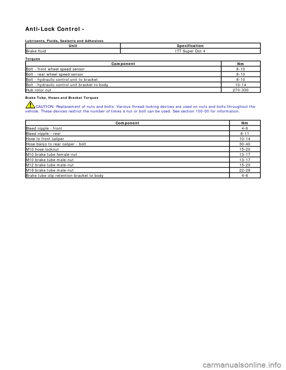
Anti-Lock Control -
Lubri
cants, Fluids, Sealants and Adhesives
Torques
Brake Tube, Hoses and Bracket Torques
CAUTI
ON: Replacement of
nuts and bolts: Various thread-locking devices are used on nuts and bolts throughout the
vehicle. These devices restrict the number of times a nut or bolt can be used. See section 100-00 for information.
UnitS
pecification
Brake flu
id
ITT Supe
r Dot 4
Com
ponent
Nm
Bol
t - front wheel speed sensor
8-
10
Bolt
- rear wheel speed sensor
8-
10
Bo
lt - hydraulic control unit to bracket
8-
10
Bolt -
hydraulic control unit bracket to body
10
-14
Hub rotor nut2
70-330
Com
ponent
Nm
Bleed n
ipple - front
4-
6
Bleed n
ipple - rear
8-1
1
Hose to fr
ont caliper
10
-14
Hose banjo to rear caliper -
bolt
30
-40
M1
0 hose locknut
15
-20
M10
brake tube female-nut
13
-17
M10
brake tube male-nut
13
-17
M12
brake tube male-nut
15
-20
M18
brake tube male-nut
22
-28
Brake tube clip retention
-bracket to body
4-
6
Page 455 of 2490
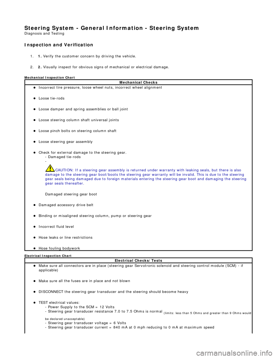
Steering System - General Inform
ation - Steering System
D
iagnosis and Testing
I
nspection and Verification
1.
1. Verify t
he customer concern by driving the vehicle.
2. 2. Visually inspect for obvious signs of mechanical or electrical damage.
Mec
hanical Inspection Chart
Electrical Inspection Chart
Mechanical Checks
Incorrect
tire pressure, loose whee
l nuts, incorrect wheel alignment
Loose ti
e-rods
Loose dam
per and spring assemblies or ball joint
Loose s
teering column shaft universal joints
Loose pinc
h bolts on steering column shaft
Loose steeri
ng gear assembly
Check f
or external damage to the steering gear.
- Damaged tie-rods
-
CAUTION: If a steering gear assemb ly is returned under warranty with leaking seals, but there is also
damage to the steering gear boot/boots the steering gear warranty will be invalid. This is due to the steering
gear seals being damaged due to fore ign materials entering the steering gear boot and damaging the steering
gear seals thereafter.
Damaged steering gear boot
Damaged accessory driv
e belt
Bin
ding or misaligned steering co
lumn, pump or steering gear
Incorrect fluid
level
Hose leaks o
r line restrictions
Hose fou
ling bodywork
El
ectrical Checks/Tests
Make sure all
connectors are in plac
e (steering gear Servotronic solenoid and steering control module (SCM) - if
applicable)
Make su
re all the fuses are in place and not blown
D
ISCONNECT the steering gear transducer
and the steering should become heavy
TEST e
lectrical values:
- Power Supply to the SCM = 12 Volts
- Steering gear transducer resist ance 7.0 to 7.5 Ohms is normal
(
limits: less than 5 Ohms and greater than 9 Ohms would
be declared unacceptable)
- Steeri
ng gear transducer voltage = 6 Volts
- Steering gear transducer cu rrent = 840 mA at 0 mph reducing to 0 mA at maximum speed
Page 461 of 2490
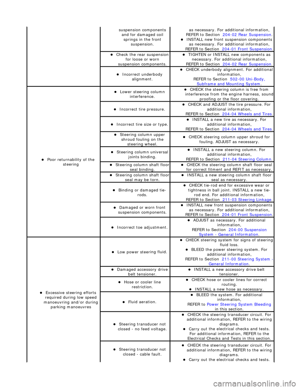
sus
pension components
and for damaged coil springs in the front suspension.
as necessary. For addi tional information,
REF
ER to Section 204
-0
2 Rear Suspension
. I
NSTALL new front suspension components
as necessary. For addi tional information,
REFER to Section 204
-01
Front Suspension
.
Chec
k the rear suspension
for loose or worn
suspension components.
TIGHTE
N or INSTALL new components as
necessary. For additi onal information,
REFER to Section 204
-0
2 Rear Suspension
.
Incorre
ct underbody
alignment.
CHECK
underbody alignment. For additional
information,
REFER to Section 502
-00
Uni
-Body, Subframe and M
ounting System
.
Poor r
eturnability of the
steering
Lower steeri
ng column
interference.
CHECK
the steering co
lumn is free from
interference from the en gine harness, sound
proofing or the floor covering.
Incorrect
tire pressure.
CHECK
and ADJUST the tire pressure. For
additional information,
REFER to Section 204
-0
4 Wheels and Tires
.
Incorrect
tire size or type.
IN
STALL a new tire as necessary. For
additional information,
REFER to Section 204
-0
4 Wheels and Tires
.
Steeri
ng column upper
shroud fouling on the steering wheel.
CHECK
steering column upper shroud for
fouling. ADJUST as necessary.
Steeri
ng column universal
joints binding.
IN
STALL a new steering column. For
additional information,
REFER to Section 211
-0
4 Steering Column
.
Steeri
ng column shaft floor
seal binding.
CHE
CK the steering column shaft floor seal
for correct fitm ent and REFIT as necessary.
Steeri
ng column shaft floor
seal may be torn.
IN
STALL a new steering column shaft floor
seal as necessary.
Bin
ding or damaged tie-
rods.
CHECK
tie-rod end for excessive wear or
tightness in ball joint. INSTALL a new tie- rod end. For additional information,
REFER to Section 211
-0
3 Steering Linkage
.
D
amaged or worn front
suspension components.
I
NSTALL new front suspension components
as necessary. For addi tional information,
REFER to Section 204
-01
Front Suspension
.
Incorre
ct toe adjustment.
AD
JUST as necessary. For additional
information,
REFER to Section 204
-00
Suspension
Sy
stem
- General
Information
.
Excessive steeri
ng efforts
required during low speed
manoeuvring and/or during parking manoeuvres
Low power steer
ing fluid.
CHE
CK steering system
for signs of steering
fluid loss.
BLEE
D the power steering system. For
additional information,
REFER to Section 211
-0
0 Steering System
- General Informati
on
.
Damaged accessory driv
e
belt tensioner.
INST
ALL a new accessory drive belt
tensioner.
Hose or cooler li
ne
restriction.
CHECK
hose or cooler lines for correct
routing.
INST
ALL a new hose as necessary.
Fl
uid aeration.
BLEE
D the system. For additional
information,
REFER to Power Steering System Bleeding
in t
his section.
Steeri
ng transducer not
closed - no feed voltage.
CHECK
the steering transducer circuit. For
additional information, REFER to the wiring diagrams.
Carry ou
t the electrical checks and tests.
For additional information, REFER to the
Electrical Checks and Tests in this section.
Steeri
ng transducer not
closed - cable fault.
CHECK
the steering transducer circuit. For
additional information, REFER to the wiring diagrams.
Carry ou
t the electrical checks and tests.