brake light switch JAGUAR X308 1998 2.G Workshop Manual
[x] Cancel search | Manufacturer: JAGUAR, Model Year: 1998, Model line: X308, Model: JAGUAR X308 1998 2.GPages: 2490, PDF Size: 69.81 MB
Page 25 of 2490

Rear Door Speaker (86.50.14)
Rear Door Tweeter Speaker (86.50.62)
Subwoofer
Speaker (86.51.05)
417: Lighting
417‐01: Exterior Lighting
Specification
Description and Operation
Exterior Lighting
Diagnosis and Testing
Exterior Lighting
Removal and Installation
Brake Pedal Position (BPP) Switch
Fog Lamp Switch (86.65.10)
Front Fog Lamp (86.
40.96)
Front Fog Lamp Bulb (86.40.94)
Front Side Marker Lamp (86.40.59)
Front Side Marker Lamp Bulb (86.40.58)
Front Turn Signal Lamp Bulb (86.40.41)
Headlamp Assembly (86.41.33)
Headlamp Leveling Motor (86.42.04)
High Beam Headlamp (86.41.34)
High Beam Headlamp Bulb (86.40.12)
High Mounted Stoplamp (86.41.01) (86.41.32)
High Mo
unted Stoplamp Bulb (86.41.02)
License Plate Lamp (86.40.86)
License Plate Lamp Bulb (86.40.85)
Low Beam Headlamp (86.41.35) ‐ Vehicles Without: Headlamp Leveling
Low Beam Headlamp (86.41.35) ‐ Vehicles With: Headlamp Leveling
Low Beam Headlamp Bulb (86.40.08)
Rear Lamp Assembly (86.40.70)
Rear Lamp Assembly Bulb (86.40.73)
Rear Side Marker La
mp (86.41.08)
Rear Side Marker Lamp Bulb (86.41.07)
Side Lamp Bulb (86.40.27)
Side Lamp/Front Turn Signal Lamp (86.40.39)
Page 318 of 2490
Comp
onent Tests
Bra
k
e Booster
1.
1. Chec k all
hoses and connections. All unused vacuum connectors should be capped. Hoses and their connections
should be correctly secured and in good condition with no holes and no collapsed areas. Inspect the valve on the
brake booster for damage.
2. 2. Check the hydraulic brake system for leaks or low fluid.
3. 3. With the transmission in PARK, stop the engine and apply the parking brake. Pump the brake pedal several times
to exhaust all vacuum in the system.
4. 4. With the engine switched off and all vacuum in the system exhausted, appl y the brake pedal and hold it down.
Start the engine. If the vacuum system is operating, the brake pedal will tend to move downward under constant
foot pressure. If no motion is felt, the vacuum booster system is not functioning.
5. 5. Remove the vacuum hose from the brake booster. Manifold vacuum should be available at the brake booster end
of the hose with the engine at idle speed and the transm ission in PARK or NEUTRAL. Make sure that all unused
vacuum outlets are correctly capped, hose connectors are correctly secured and vacuum hoses are in good
condition. When it is established that manifold vacuum is available to the brake booster, connect the vacuum hose
to the brake booster and repeat Step 3. If no downward movement of the brake pedal is felt, install a new brake
booster.
6. 6. Operate the engine for a minimum of 10 seconds at a fast idle. Stop the engine and allow the vehicle to stand for
10 minutes. Then, apply th e brake pedal with approximately 89 N ( 20lb) of force. The pedal feel (brake
application) should be the same as that noted with the engine running. If the brake pedal feels hard (no power
assist), install a new valve and then re peat the test. If the brake pedal still feels hard, in stall a new brake booster.
If the brake pedal movement feels spongy, bleed the brak e system. For additional information, refer to General
Procedures in this section.
Bra k
e Master Cylinder
Usual
l
y, the first and strongest
indicator of anything wrong in the brake syst em is a feeling through the brake pedal. In
diagnosing the condition of the brake master cylinder, check pedal feel as evidence of a brake concern. Check for brake
warning lamp illumination and the brake fluid le vel in the brake master cylinder reservoir.
Normal Conditio
ns
The fo
llowing conditions are considered norm
al and are not indications that the brake master cylinder is in need of repair.
New bra
ke systems are designed to produc
e a pedal effort that is not as hard as in the past. Complaints of light
pedal efforts should be compared to the pedal effort s of another vehicle of the same model and year.
The fl
uid level will fall with brake pad wear.
Abnormal Conditions
•
NOTE: Prior to carrying out any diag
nosis, make sure the brake system warning indicator is functional.
Changes in the brake pedal feel or brake pedal travel are in dicators that something could be wrong in the brake system. The
diagnostic procedure and techniques use brake pedal feel, warning indicator illu mination and low brake fluid level as
indicators to diagnosing brake system co ncerns. The following conditions are cons idered abnormal and indicate that the
brake master cylinder is in need of repair:
Brake ped a
l goes down fast. Th
is could be caused by an ex ternal or internal leak.
Brake pedal goes down slowly
. This could be
caused by an internal or external leak.
Brak
e pedal is low or feels spongy. This condition may be ca
used by no fluid in the brake master cylinder, reservoir
Page 391 of 2490
Parking Brake and Ac
tu
ation - Parking Brake
Description an
d Operation
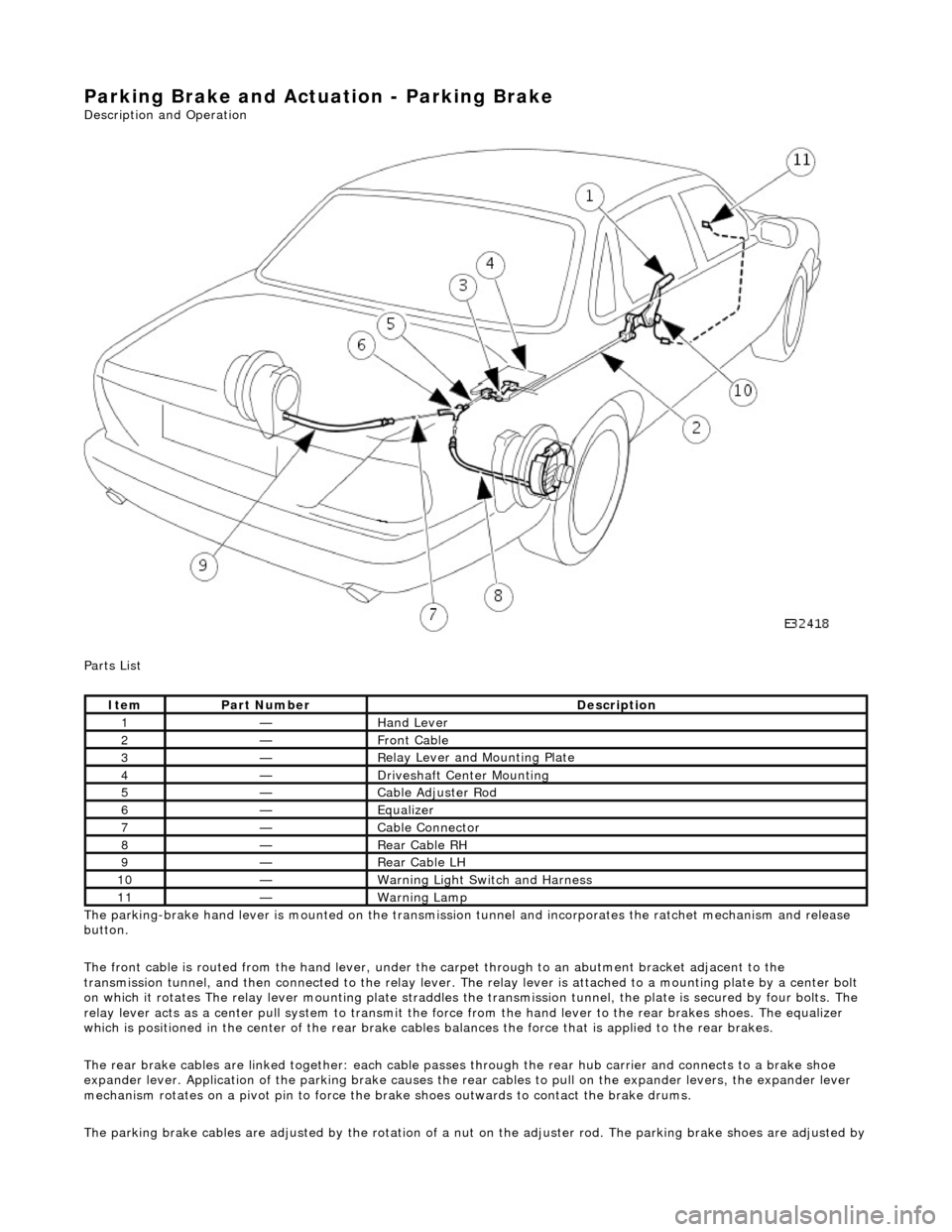
Parts List
The parking-brake hand lever is mounted on the transmission tunnel and incorporates the ratchet mechanism and release
button.
The front cable is routed from the hand lever, under the carpet through to an abutment bracket adjacent to the
transmission tunnel, and then connected to the relay lever. The relay lever is attached to a mounting plate by a center bolt
on which it rotates The relay lever mounting plate straddles the transmission tunnel, the plate is secured by four bolts. The
relay lever acts as a center pu ll system to transmit the force from the hand lever to the rear brakes shoes. The equalizer
which is positioned in the center of the rear brake cables balances the force that is applied to the rear brakes.
The rear brake cables are linked together: each cable passes through the rear hub carrier and connects to a brake shoe
expander lever. Application of the parking brake causes the rear cables to pu ll on the expander levers, the expander lever
mechanism rotates on a pivot pin to force the brake shoes outwards to contact the brake drums.
The parking brake cables are adjusted by the rotation of a nu t on the adjuster rod. The parking brake shoes are adjusted by
It
em
Par
t Number
De
scription
1—Hand Le
ver
2—Front Cable
3—R
elay Lever and Mounting Plate
4—Drivesh
aft Center Mounting
5—Cable Adjuster Rod
6—Equalize
r
7—Cable Connector
8—Rear Ca
ble RH
9—Rear Ca
ble LH
10—Warn
ing Light Switch and Harness
11—War
ning Lamp
Page 396 of 2490
Parking Brake and Actuation - P
arking Brake Control
Re
mo
val and Installation
Remov
a
l
W
A
RNING: BRAKE DUST, IF INHALED CAN DAMAGE YOUR
HEALTH. ALWAYS REMOVE BRAKE DUST USING A VACUUM
BRUSH. DO NOT USE A COMPRESSED-AIR LINE TO DISPERSE BRAKE DUST INTO THE ATMOSPHERE.
CAUTION: Replacement of nuts and bolts: Various thread-locking devices are used on nuts and bolts throughout the
vehicle. These devices restrict the number of times a nut or bolt can be used. See section 100-00 for information.
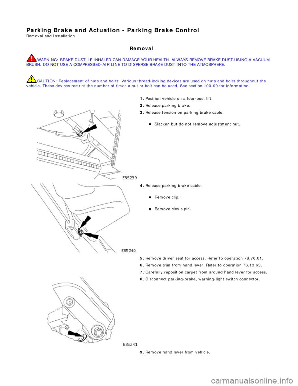
1. Position vehi cl
e on a four-post lift.
2. Release parking brake.
3. Releas
e tension on parking brake cable.
Slacken bu
t do not remove adjustment nut.
4. Releas
e parking brake cable.
Remo
ve clip.
Re
mo
ve clevis pin.
5. Remove driver seat for access . Refer to operation 76.70.01.
6. Remove trim from hand lever. Refer to operation 76.13.63.
7. Carefully reposition carpet from around hand lever for access.
8. Disconnect park ing-br
ake, warning-light switch connector.
9. Remove hand lever from vehicle.
Page 397 of 2490

I
nstallation
Re
move bolts.
R
emove lever.
10
.
Remove gasket.
11
.
Remove warning-light switch from lever.
R
emove screws.
Re
move switch.
1. Inst
all warning-light switch to hand lever.
Install and tigh
ten
screws to 3 Nm.
2. Install gasket to handbrake lever.
Page 398 of 2490
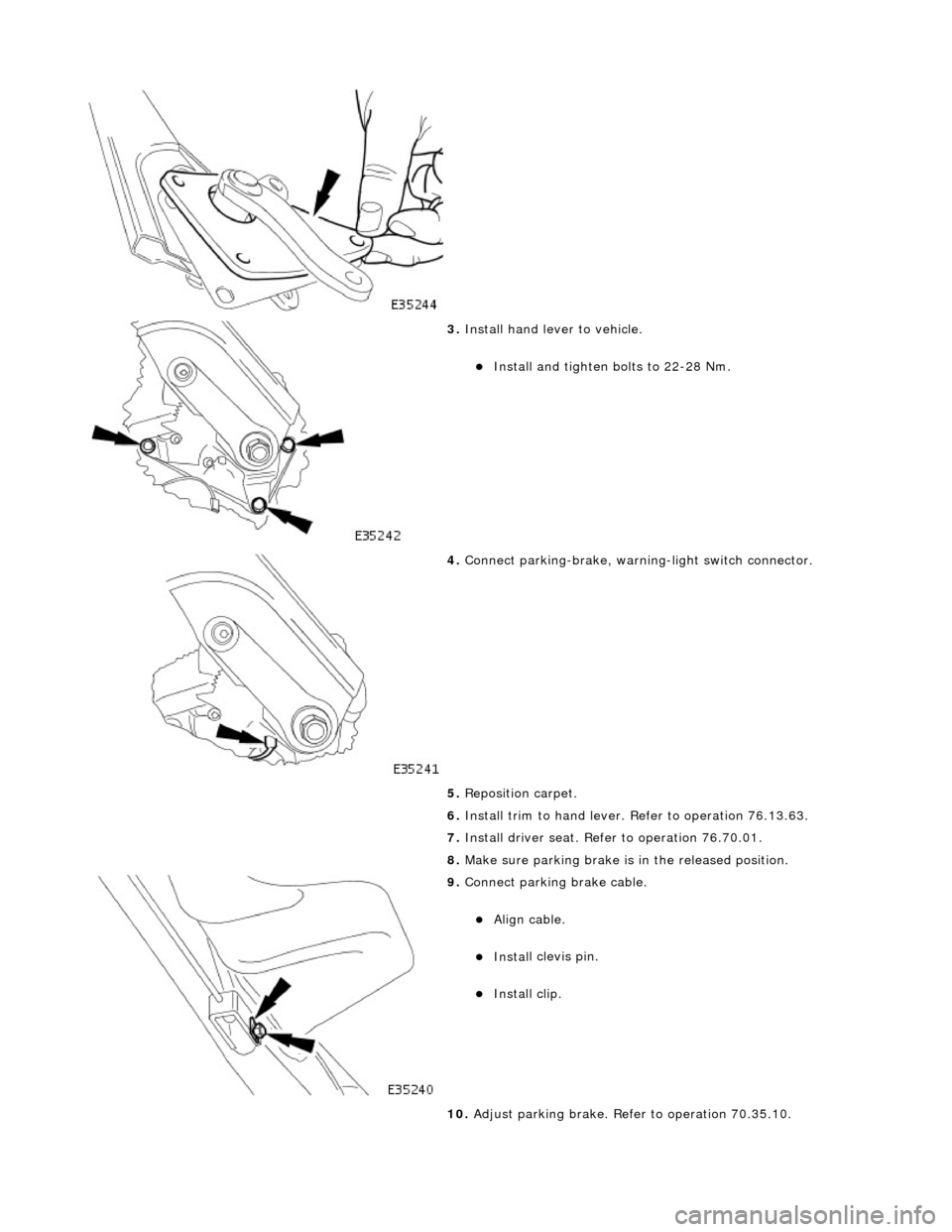
3. Instal
l hand lever to vehicle.
Install and tighten bolts to 2
2-28 Nm.
4. Connect park
ing-brake, warnin
g-light switch connector.
5. Reposition carpet.
6. Install trim to hand lever. Refer to operation 76.13.63.
7. Install driver seat. Refer to operation 76.70.01.
8. Make sure parking brake is in the released position.
9. Connect p a
rking brake cable.
Align ca
ble
.
Inst
al
l clevis pin.
Inst
al
l clip.
10. Adjust parking brake. Refer to operation 70.35.10.
Page 414 of 2490
Hydrau
lic Brake Actuation - Brake Pedal and Bracket
Re
mo
val and Installation
Remov
a
l
• C
A
UTIONS:
Replacement of nuts and bolts: Various thread-locking de vices are used on nuts and bolts throughout the vehicle.
These devices restrict the number of times a nut or bolt can be used. See section 100-00 for information.
Remove brake fluid spilla ge immediately from paint work, with clean water.
In
stallation
1.
Position vehicl
e on a four-post lift.
2. Open hood and fit suitable pa intwork protection equipment.
3. Disconnect battery ground cabl e. (IMPORTANT, see 86.15.19
for further information).
4. Remove engine compartment rear cover. Refer to operation
76.11.35.
5. Remove pedal housing, brake booster and master cylinder
assembly. Refer to operation 70.35.39.
6. Remove brake booster and master cylinder assembly. Refer to
operation 70.50.18.
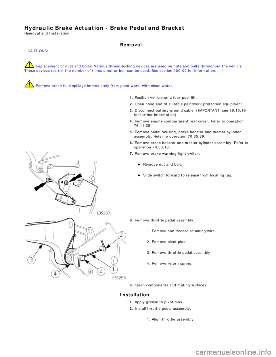
7. Remove brake wa
rning-light switch.
Remove n
u
t and bolt.
Slide sw
itch forward to release from locating tag.
8. Re
move throttle pedal assembly.
1. Remove and discard retaining wire.
2. Remove pivot pins.
3. Remove throttle pedal assembly.
4. Remove return spring.
9. Clean components and mating surfaces.
1. Apply grease to pivot pins.
2. Install throttle pedal assembly.
1. Align throttle assembly.
Page 415 of 2490
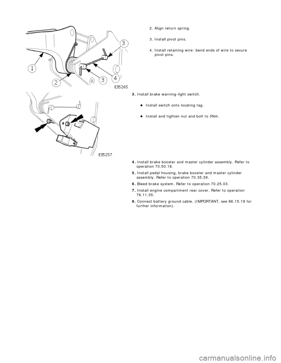
2
. Align return spring.
3. Install pivot pins.
4. Install retaining wire: bend ends of wire to secure
pivot pins.
3. Inst
all brake warning-light switch.
Inst
all switch onto locating tag.
Install and tigh
ten nut and bolt to 3Nm.
4. Install brake booster and master cylinder assembly. Refer to
operation 70.50.18.
5. Install pedal housing, brake booster and master cylinder
assembly. Refer to operation 70.35.39.
6. Bleed brake system. Refer to operation 70.25.03.
7. Install engine compartment rear cover. Refer to operation
76.11.35.
8. Connect battery ground cable. (IMPORTANT, see 86.15.19 for
further information).
Page 432 of 2490
It is a reciprocating two
-circuit pu
mp in which one brake circuit is as signed to each pump circuit.
It supplies th
e fluid pressure and vo
lume to supply the brake circuits under ABS and Traction control.
The pump is driven by an electri
c motor, with the pump
housing incorporating two lo w pressure accumulators and
damping chambers for each brake circuit.
The ac cu
mulator stores the pressure and smooths out the output pu
lses from the pump.
ABS Warning Lamp
The sys
tem will be set in a fail-safe mode if a problem is de
tected; a warning lamp on the instrument panel will notify the
driver there is a problem.
Anti-Lock Braking Sy
stem (ABS)
The AB
S components are combined with
an hydraulic booster and a tandem master cylinder to provide a two circuit braking
system. The system comprises, four wheel speed sensor s, a brake control modulator and an ABS warning lamp.
Should a wheel start to lock-up during braking a signal tr ansmitted from the wheel speed sensor to the brake control
modulator will start the hydraulic pump. The brake control modula tor will close the input valve of the line connected to the
locked-wheel to stop any increase in fluid pressure to the br ake caliper. If this fails to prevent the wheel locking, the
pressure in the caliper will be decreased by opening the return valve until th e wheel starts accelerating again. The fluid
pressure from the return va lve is directed into the low pressure accumulator, housed in the pump.
From the low pressure accumulator, fl uid is pumped through the damping cham ber to the brake master cylinder. The
pressure to the brake caliper will then be increased in small steps to maintain maximum adhesion between the tire and road
surface. This is achieved by closing the return valve, and opening the input valve and using the hydraulic pump to increase
the pressure.
Although the system senses all four wheels independently, the rear wheels are regulated as a pair. If a sensor on a rear
wheel detects a wheel decelerating rapidly, then the fluid pressure to both wheels is reduced. The fluid pressure is then
dictated by the wheel having the lowe st adhesion with the road surface.
The ABS system will be set in a fail-safe mode if a problem is detected; a warn ing lamp on the instrument panel will notify
the driver there is a problem. The brake system will still operate conventionally and with the same standard of performance
as a vehicle not equipped with ABS.
Automa tic Stability Control (ASC)
Th
e ASC utilizes the ABS sensing arrangement to provide the maximum traction force to propel the vehicle.
The ASC is switched on when the engine is started. The system can be switched off by pressing the 'ASC OFF' (the switched
is marked 'TRAC OFF' on vehicles fitted with traction control). The switch, which is situated in the center console switchpack,
lights up to warn that the system is sw itched off. An 'ASC' amber warning light flashes on the instrument panel when the
system detects a spinning wheel.
The ASC system uses engine intervention to reduce the torque delivered to the drive wheels to prevent them spinning.
Engine torque is re duced in three ways:
The
throttle is moved towards the closed position.
The ignition is retarded. F
u
el is cut-off at the cylinder injectors.
Wheel spin is detected by the wheel sp eed sensors and communicated to the AB S/TCCM. The ABS/TCCM uses information
from the controller area network (CAN) to calculate the torque that the engine should produce to stop the wheel spinning.
Torque reductions are then requested from the engine control module (ECM ) through the CAN. The throttle is then
positioned to provide the target torque, which has been calculated to prevent wheel spin. During the transient phase of
torque reduction the fuel is cut-off and th e ignition retarded Both the fuel cut-off an d ignition retard will be restored to
normal when the throttle is set to its new position.
The ASC uses a brake control modulator with six solenoid va lves: three normally open inlet valves and three normally
Page 1921 of 2490
License plate lamps
Each license plate bulb is accessible after removing the relevant lens. The license plate lamps can be accessed following
removal of the trunk lid liner and upper trim finisher.
Rear lamp assembly
Each rear lamp assembly incorporates a stop/tail lamp, a fog lamp, a reversing lamp and a direction indicator lamp. Access
for bulb replacement is from the trunk.
Side markers
Each side marker is retained in the bumper cover by a lug on one end of the unit and a spring clip at the other end. The unit is not electrically connected for all markets.
High mounted stop lamp
The high mounted stop lamp (HMSL) is secu red to studs on the center lower edge of the backlight and provides illumination
using five bulbs.
Operation
All lamps are controlled by the BPM which pr ovides an appropriate output in response to an input received when a selected
switch is operated.
The side marker lamps receive an input from the BPM via relay 3 and fuse F21. The license plate lamps receive an input
from the BPM via relay 3 and fuse F19. The rela y and fuses are located in the trunk fuse-box.
The tail lamps receive an input direct from the BPM.
The stop, reversing and rear fog lamps are controlled by the security and locking module (SLM) which receives inputs via
the SCP network from the BPM.
The HMSL is not controlled by the SLM; it receives input from the brake switch via relay 5 and fuse F8 in the trunk fuse-box.
The BPM and SLM monitor the stop lamps (n ot HMSL) and tail lamps for failure.
Fault analysis must be undertaken using the PDU, refer to Diagnosis and Testing.
Consult the relevant Electrical Guid e for details of circuit operation.
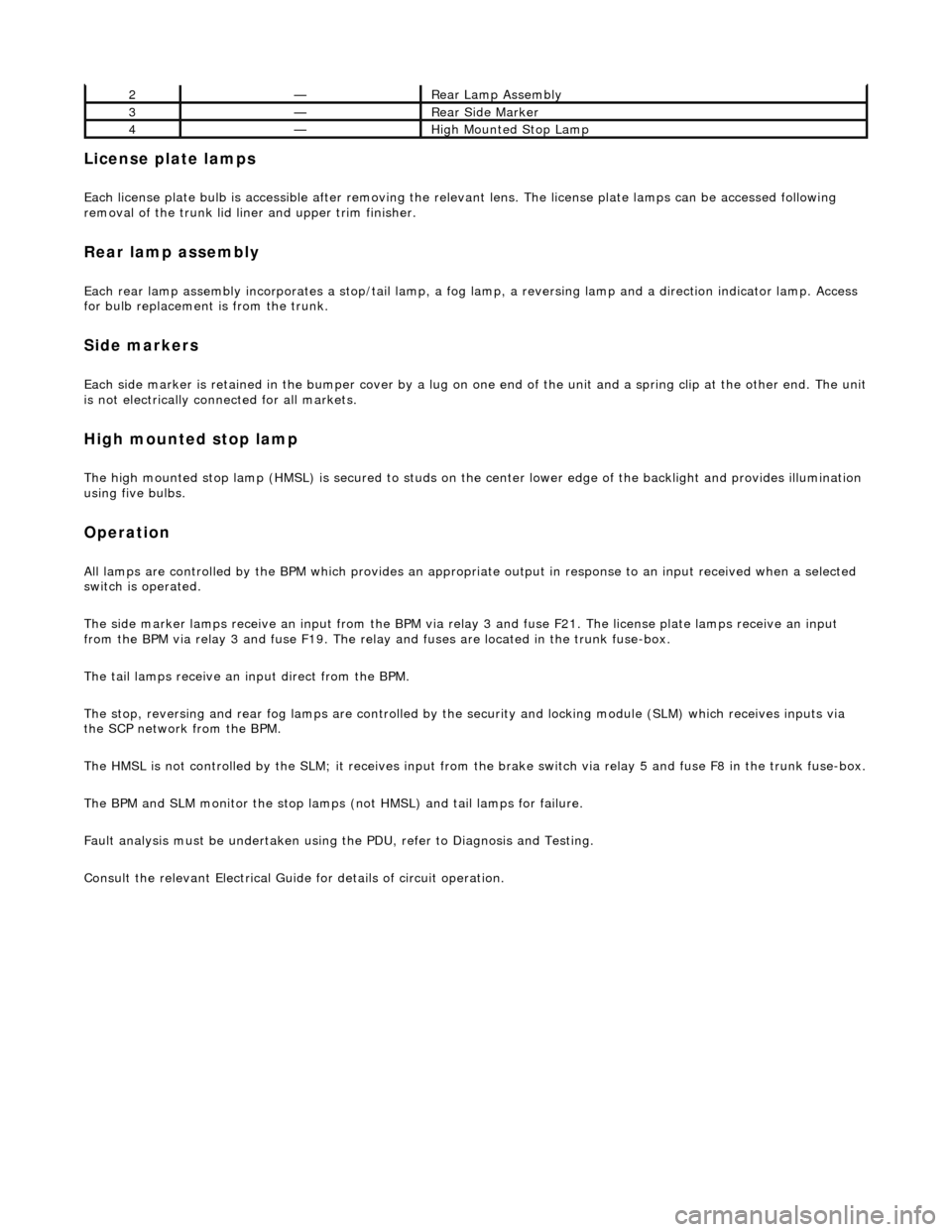
2—Rear Lamp Assembly
3—Rear Side Marker
4—High Mounted Stop Lamp