coolant type JAGUAR X308 1998 2.G Workshop Manual
[x] Cancel search | Manufacturer: JAGUAR, Model Year: 1998, Model line: X308, Model: JAGUAR X308 1998 2.GPages: 2490, PDF Size: 69.81 MB
Page 729 of 2490
Engine - Intake Manifold LH
In-vehicle Repair
Removal
WARNING: BEFORE PROCEEDING, IT IS ESSENTIAL THAT THE WARNINGS GIVEN IN SECTION 100-00 (UNDER THE
HEADING 'SAFETY PRECAUTIONS') ARE READ AND UNDERSTOOD. 1.
Open the engine compartment and fit paintwork protection
sheets.
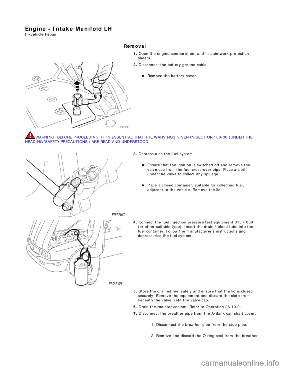
2. Disconnect the batt ery ground cable.
Remove the battery cover.
3. Depressurise the fuel system.
Ensure that the ignition is switched off and remove the
valve cap from the fuel cross-over pipe. Place a cloth
under the valve to collect any spillage.
Place a closed container, su itable for collecting fuel,
adjacent to the vehicle. Remove the lid.
4. Connect the fuel injection pres sure test equipment 310 - 058
(or other suitable type). Insert the drain / bleed tube into the
fuel container. Follow the ma nufacturer's instructions and
depressurise the fuel system.
5. Store the drained fuel safely and ensure that the lid is closed
securely. Remove the equipmen t and discard the cloth from
beneath the valve. refit the valve cap.
6. Drain the radiator coolant. Refer to Operation 26.10.01.
7. Disconnect the breather pipe fro m the A-Bank camshaft cover.
1. Disconnect the breather pipe from the stub pipe.
2. Remove and discard the O-ring seal from the breather
Page 734 of 2490
Engine - Intake Manifold RH
In-vehicle Repair
Removal
WARNING: BEFORE PROCEEDING, IT IS ESSENTIAL THAT THE WARNINGS GIVEN IN SECTION 100-00 (UNDER THE
HEADING 'SAFETY PRECAUTIONS') ARE READ AND UNDERSTOOD. 1.
Open the engine compartment and fit paintwork protection
sheets.
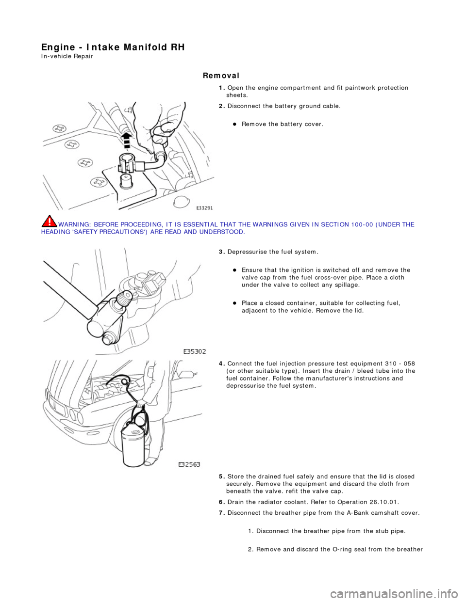
2. Disconnect the batt ery ground cable.
Remove the battery cover.
3. Depressurise the fuel system.
Ensure that the ignition is switched off and remove the
valve cap from the fuel cross-over pipe. Place a cloth
under the valve to collect any spillage.
Place a closed container, su itable for collecting fuel,
adjacent to the vehicle. Remove the lid.
4. Connect the fuel injection pres sure test equipment 310 - 058
(or other suitable type). Insert the drain / bleed tube into the
fuel container. Follow the ma nufacturer's instructions and
depressurise the fuel system.
5. Store the drained fuel safely and ensure that the lid is closed
securely. Remove the equipmen t and discard the cloth from
beneath the valve. refit the valve cap.
6. Drain the radiator coolant. Refer to Operation 26.10.01.
7. Disconnect the breather pipe fro m the A-Bank camshaft cover.
1. Disconnect the breather pipe from the stub pipe.
2. Remove and discard the O-ring seal from the breather
Page 739 of 2490
Engine - Intake Manifold Gasket LH
In-vehicle Repair
Removal
WARNING: BEFORE PROCEEDING, IT IS ESSENTIAL THAT THE WARNINGS GIVEN IN SECTION 100-00 (UNDER THE
HEADING 'SAFETY PRECAUTIONS') ARE READ AND UNDERSTOOD. 1.
Open the engine compartment and fit paintwork protection
sheets.
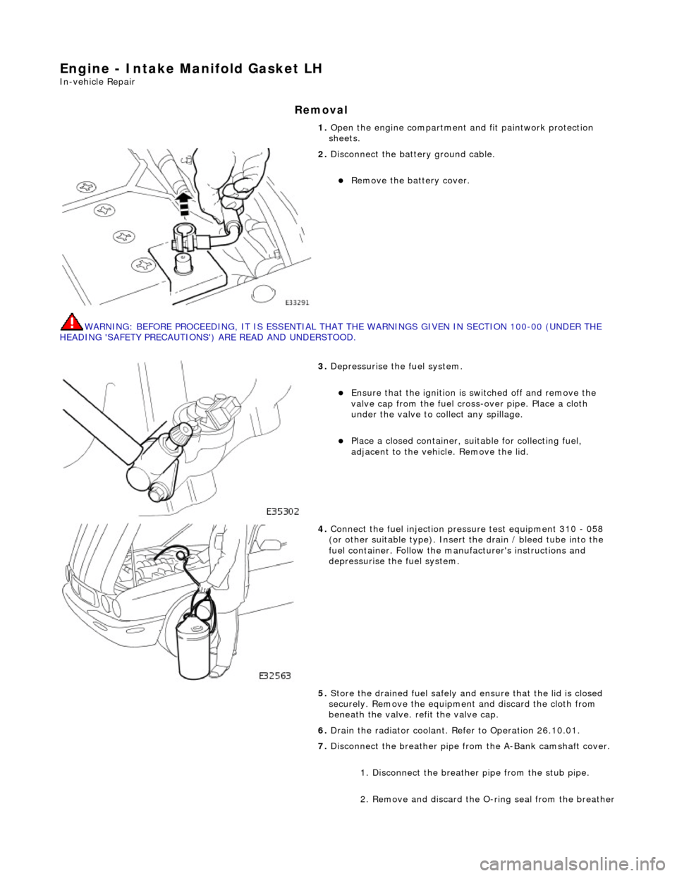
2. Disconnect the batt ery ground cable.
Remove the battery cover.
3. Depressurise the fuel system.
Ensure that the ignition is switched off and remove the
valve cap from the fuel cross-over pipe. Place a cloth
under the valve to collect any spillage.
Place a closed container, su itable for collecting fuel,
adjacent to the vehicle. Remove the lid.
4. Connect the fuel injection pres sure test equipment 310 - 058
(or other suitable type). Insert the drain / bleed tube into the
fuel container. Follow the ma nufacturer's instructions and
depressurise the fuel system.
5. Store the drained fuel safely and ensure that the lid is closed
securely. Remove the equipmen t and discard the cloth from
beneath the valve. refit the valve cap.
6. Drain the radiator coolant. Refer to Operation 26.10.01.
7. Disconnect the breather pipe fro m the A-Bank camshaft cover.
1. Disconnect the breather pipe from the stub pipe.
2. Remove and discard the O-ring seal from the breather
Page 744 of 2490
Engine - Intake Manifold Gasket RH
In-vehicle Repair
1. Open the engine compartment and fit paintwork protection
sheets.
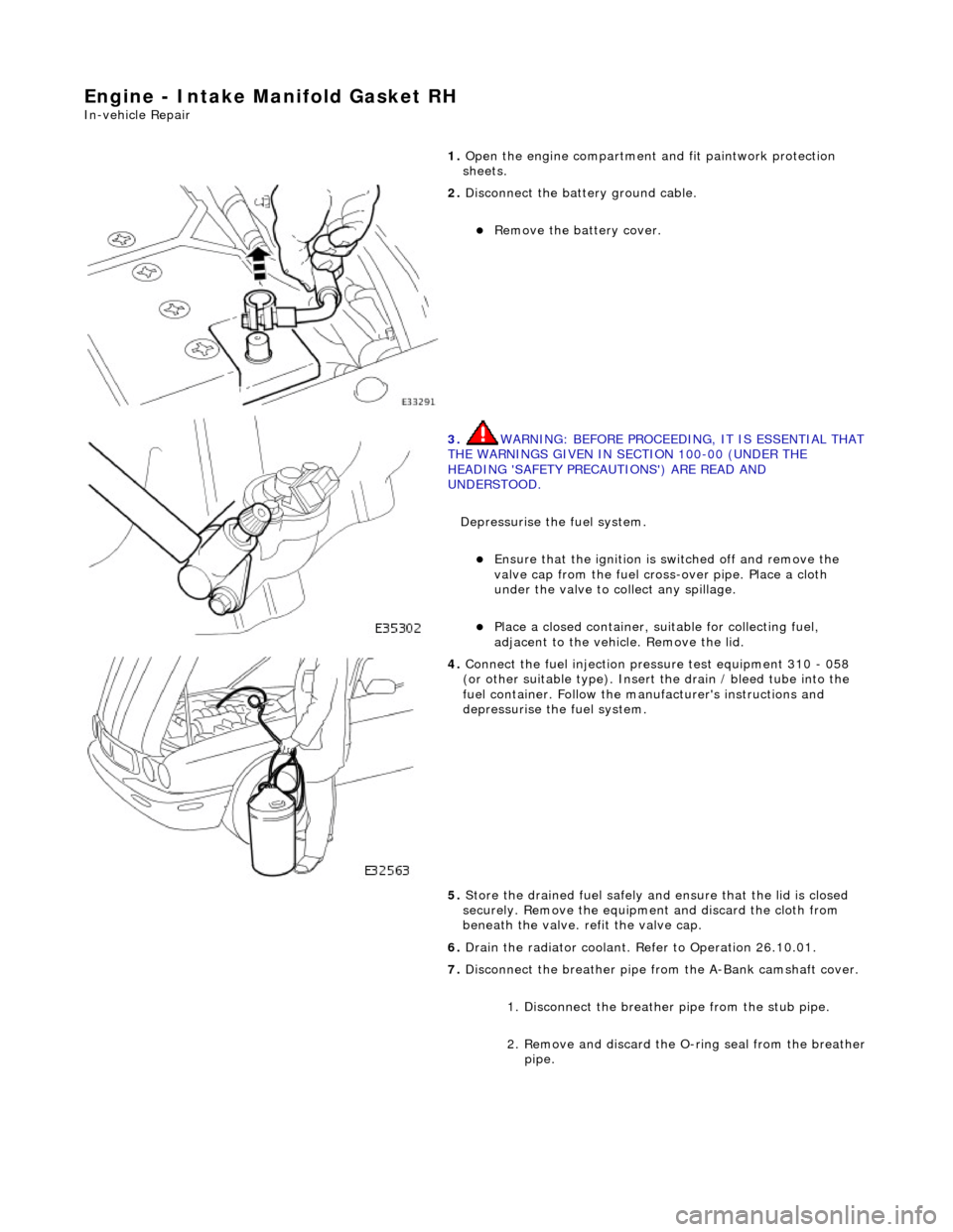
2. Disconnect the batt ery ground cable.
Remove the battery cover.
3. WARNING: BEFORE PROCEEDING, IT IS ESSENTIAL THAT THE WARNINGS GIVEN IN SECTION 100-00 (UNDER THE
HEADING 'SAFETY PRECAUTIONS') ARE READ AND
UNDERSTOOD.
Depressurise the fuel system.
Ensure that the ignition is switched off and remove the
valve cap from the fuel cross-over pipe. Place a cloth
under the valve to collect any spillage.
Place a closed container, su itable for collecting fuel,
adjacent to the vehicle. Remove the lid.
4. Connect the fuel injection pres sure test equipment 310 - 058
(or other suitable type). Insert the drain / bleed tube into the
fuel container. Follow the ma nufacturer's instructions and
depressurise the fuel system.
5. Store the drained fuel safely and ensure that the lid is closed
securely. Remove the equipmen t and discard the cloth from
beneath the valve. refit the valve cap.
6. Drain the radiator coolant. Refer to Operation 26.10.01.
7. Disconnect the breather pipe fro m the A-Bank camshaft cover.
1. Disconnect the breather pipe from the stub pipe.
2. Remove and discard the O-ring seal from the breather
pipe.
Page 958 of 2490
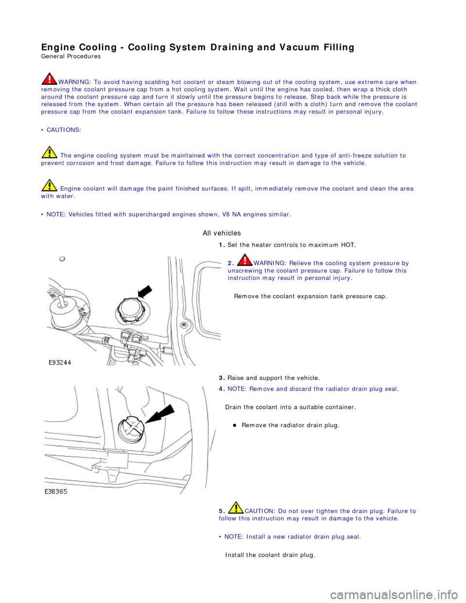
Engine Cooling - Cooling System Draining and Vacuum Filling
Gene
ral Procedures
WARNING: To avoid having scalding ho t coolant or steam blowing out of the cooling system, use extreme care when
removing the coolant pressure cap from a hot cooling system. Wait until the engine has cooled, then wrap a thick cloth
around the coolant pressure cap and turn it slowly until the pressure begins to release. Step ba ck while the pressure is
released from the system. When certain al l the pressure has been released (still with a cloth) turn and remove the coolant
pressure cap from the coolant expansion tank. Failure to fo llow these instructions may result in personal injury.
• CAUTIONS:
The engine cooling syst em must be maintained with the correct concentration and type of anti-freeze solution to
prevent corrosion and frost damage. Failure to follow th is instruction may result in damage to the vehicle.
Engine coolant will damage the paint finished surfaces. If spilt, immediately remove the coolant and clean the area
with water.
• NOTE: Vehicles fitted with supercharged engines shown, V8 NA engines similar.
All vehicles
1. Set
the heater controls to maximum HOT.
2. WARN
ING: Relieve the cooling system pressure by
unscrewing the coolant pressure cap. Failure to follow this
instruction may result in personal injury.
Remove the coolant expans ion tank pressure cap.
3. Raise a
nd support the vehicle.
4. NOTE : Remov
e and discard the
radiator drain plug seal.
Drain the coolant into a suitable container.
Remove the radiato
r drain plug.
5. CAUTION: Do not over tighten the drain plug. Failure to
follow this instruction may result in damage to the vehicle.
• NOTE: Install a new radiator drain plug seal.
Install the coolant drain plug.
Page 1020 of 2490
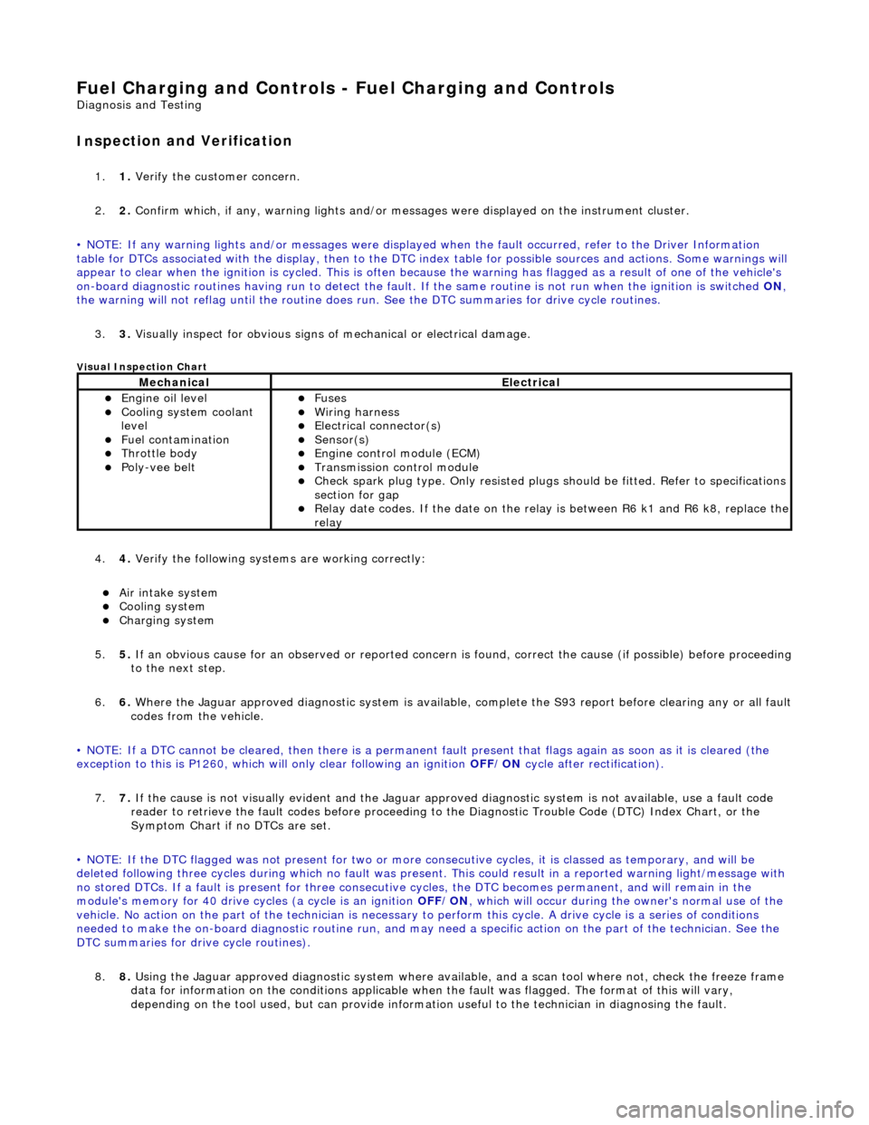
Fuel Char
ging and Controls - Fuel Charging and Controls
D
iagn
osis and Testing
I
n
spection and Verification
1.
1. Veri fy the customer concern.
2. 2. Confi
rm which, if any, warning li
ghts and/or messages were displayed on the instrument cluster.
• NOTE: If any warning lights and/or me ssages were displayed when the fault occurred, refer to the Driver Information
table for DTCs associated with the display, then to the DTC index table for possible sources and actions. Some warnings will
appear to clear when the ignition is cycl ed. This is often because the warning has flagged as a resu lt of one of the vehicle's
on-board diagnostic routines having run to detect the fault. If the same routine is not run when the ignition is switched ON,
the warning will not reflag until the routine does run. See the DTC summaries for drive cycle routines.
3. 3. Visually inspect for obvious signs of mechanical or electrical damage.
Vi
sual Inspection Chart
4.
4. Veri fy the foll
owing syst
ems are working correctly:
Air intake
system
Cooling system
Charging system
5. 5. If
an obvious cause for an observed or
reported concern is found, correct th e cause (if possible) before proceeding
to the next step.
6. 6. Where the Jaguar approved diagnostic sy stem is available, complete the S93 report before clearing any or all fault
codes from the vehicle.
• NOTE: If a DTC cannot be cleared, then there is a permanent fault present that flag s again as soon as it is cleared (the
exception to this is P1260, which will only clear following an ignition OFF/ON cycle after rectification).
7. 7. If the cause is not visually evident and the Jaguar approv ed diagnostic system is not available, use a fault code
reader to retrieve the fault codes be fore proceeding to the Diagnostic Trou ble Code (DTC) Index Chart, or the
Symptom Chart if no DTCs are set.
• NOTE: If the DTC flagged was not present for two or more co nsecutive cycles, it is classed as temporary, and will be
deleted following three cycl es during which no fault was present. This could result in a reported wa rning light/message with
no stored DTCs. If a fault is present for three consecutive cycles, the DTC becomes permanent, and will remain in the
module's memory for 40 drive cycl es (a cycle is an ignition OFF/ON, which will occur during the owner's normal use of the
vehicle. No action on the part of the technician is necessary to perform this cycle. A drive cycle is a series of conditions
needed to make the on-board diagnostic ro utine run, and may need a specific action on the part of the technician. See the
DTC summaries for drive cycle routines).
8. 8. Using the Jaguar approved diagnostic system where available, and a scan tool where not, check the freeze frame
data for information on the conditions applicable when the fault was flagged. The format of this will vary,
depending on the tool used, but can pr ovide information useful to the technician in diagnosing the fault.
MechanicalElectrical
Engine
oil level
Coo
ling system coolant
lev
el
Fuel contamination
Throttle body Poly-ve
e belt
Fu
ses
W
i
ring harness
E
l
ectrical connector(s)
Sens
o
r(s)
Engine
control module (E
CM)
Tran
s
mission control module
Check spark plu
g type. Only r
e
sisted plugs should be fitted. Refer to specifications
section for gap
Relay date codes. I
f the date on the rela
y is between R6 k1 and R6 k8, replace the
relay
Page 1189 of 2490
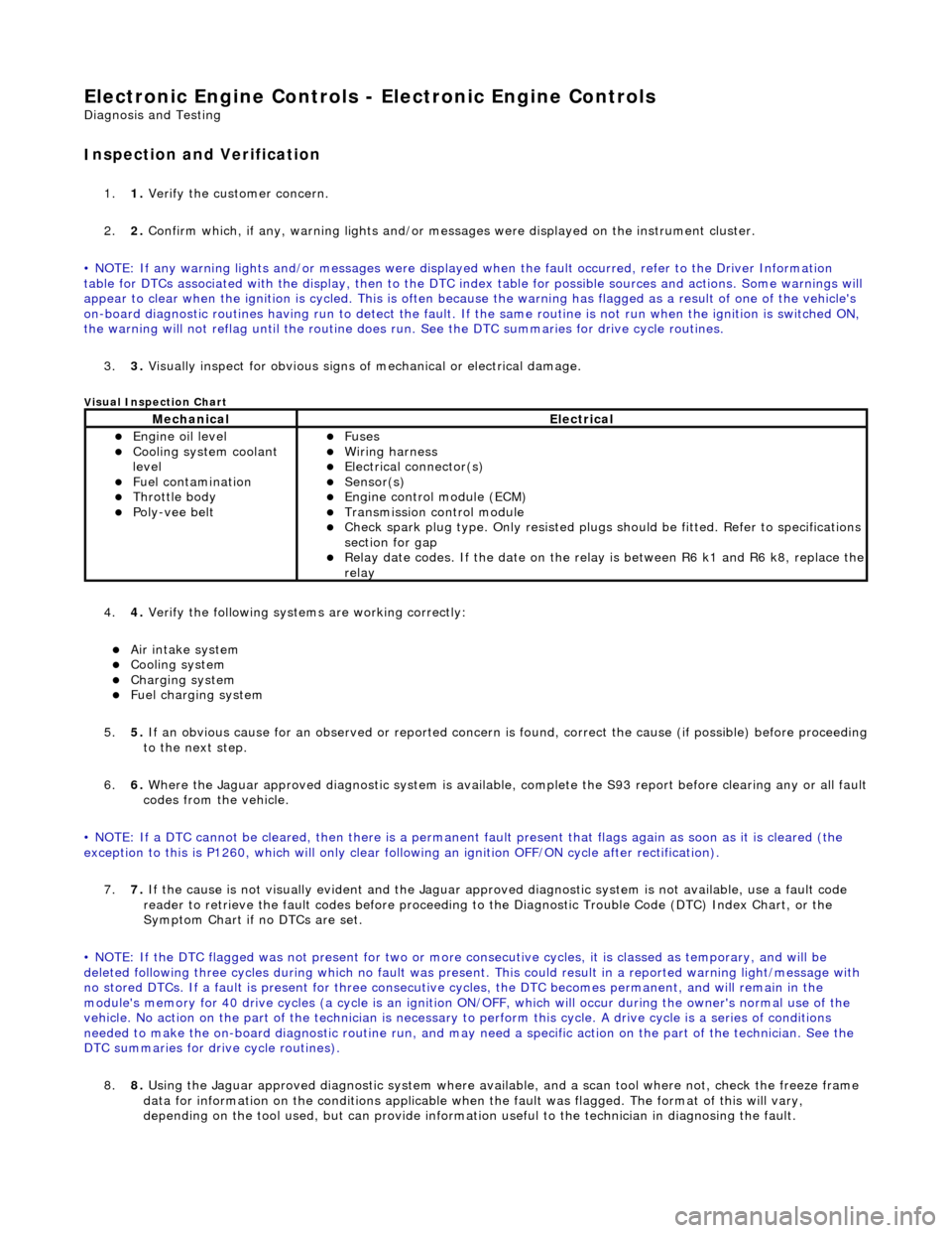
E
lectronic Engine Controls -
Electronic Engine Controls
D
iagnosis and Testing
I
nspection and Verification
1.
1. Veri
fy the customer concern.
2. 2. Confirm which, if any, warning li ghts and/or messages were displayed on the instrument cluster.
• NOTE: If any warning lights and/or me ssages were displayed when the fault occurred, refer to the Driver Information
table for DTCs associated with the display, then to the DTC index table for possible sources and actions. Some warnings will
appear to clear when the ignition is cycl ed. This is often because the warning has flagged as a resu lt of one of the vehicle's
on-board diagnostic routines having run to detect the fault. If the same routine is not run when the ignition is switched ON,
the warning will not reflag until the routine does run. See the DTC summaries for drive cycle routines.
3. 3. Visually inspect for obvious signs of mechanical or electrical damage.
V
isual Inspection Chart
4.
4. Veri
fy the following syst
ems are working correctly:
Air in
take system
Coo
ling system
Charging system
F
uel charging system
5. 5. If an obvious cause for an observed or reported concern is found, correct the cause (if possible) before proceeding
to the next step.
6. 6. Where the Jaguar approved diagnostic sy stem is available, complete the S93 report before clearing any or all fault
codes from the vehicle.
• NOTE: If a DTC cannot be cleared, then there is a permanent fault present that flag s again as soon as it is cleared (the
exception to this is P1260, which will only clear following an ignition OFF/ON cycle after rectification).
7. 7. If the cause is not visually evident and the Jaguar approv ed diagnostic system is not available, use a fault code
reader to retrieve the fault codes be fore proceeding to the Diagnostic Trou ble Code (DTC) Index Chart, or the
Symptom Chart if no DTCs are set.
• NOTE: If the DTC flagged was not present for two or more co nsecutive cycles, it is classed as temporary, and will be
deleted following three cycl es during which no fault was present. This could result in a reported wa rning light/message with
no stored DTCs. If a fault is present for three consecutive cycles, the DTC becomes permanent, and will remain in the
module's memory for 40 drive cycles (a cy cle is an ignition ON/OFF, which will occur during the owner's normal use of the
vehicle. No action on the part of the technician is necessary to perform this cycle. A drive cycle is a series of conditions
needed to make the on-board diagnostic ro utine run, and may need a specific action on the part of the technician. See the
DTC summaries for driv e cycle routines).
8. 8. Using the Jaguar approved diagnostic system where available, and a scan tool where not, check the freeze frame
data for information on the conditions applicable when the fault was flagged. The format of this will vary,
dependin
g o
n the tool used, but can provide information useful to the technician in dia
gnos
in
g th
e fault.
MechanicalElectrical
Engi
ne oil level
Coo
ling system coolant
level
Fuel contamination
Throttle body Poly
-vee belt
F
uses
W
iring harness
E
lectrical connector(s)
Sens
or(s)
Engine
control module (ECM)
Tran
smission control module
Check spark plu
g type. Only re
sisted plugs should be fitted. Refer to specifications
section for gap
Relay date codes.
If the date on the rela
y is between R6 k1 and R6 k8, replace the
relay
Page 1462 of 2490
Transmission/Transaxle Cooling - 4.0L NA V8 - AJ27/3.2L NA V8 - AJ26 -
Transmission Cooling
Description and Operation
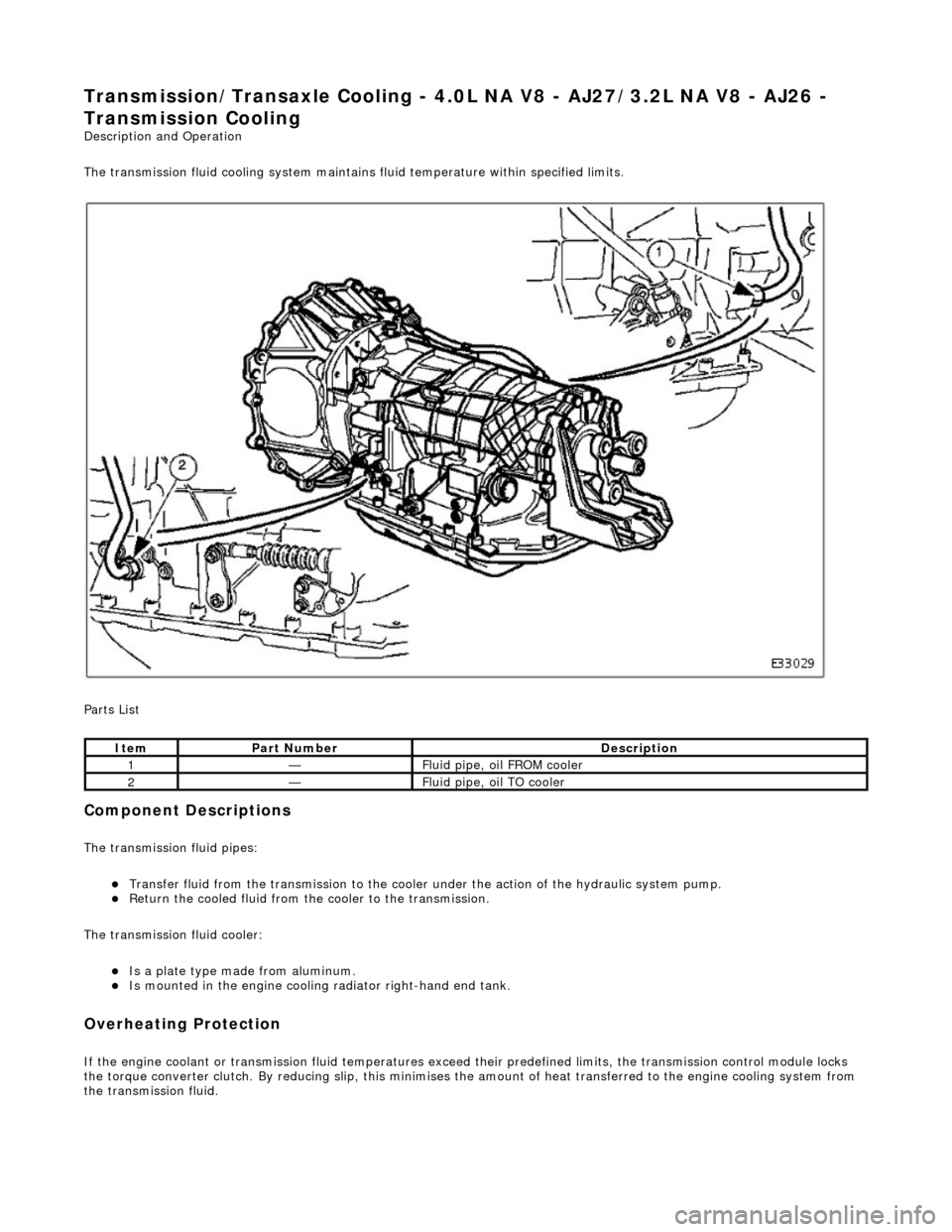
The transmission fluid cooling system maintains fluid temperature within specified limits.
Parts List
Component Descriptions
The transmission fluid pipes:
Transfer fluid from the transmission to the cooler under the action of the hydraulic system pump. Return the cooled fluid from th e cooler to the transmission.
The transmission fluid cooler:
Is a plate type made from aluminum. Is mounted in the engi ne cooling radiator right-hand end tank.
Overheating Protection
If the engine coolant or transm ission fluid temperatures exceed their predefined limits, th e transmission control module locks
the torque converter clutch. By reducing slip, this minimises th e amount of heat transferred to the engine cooling system from
the transmission fluid.
ItemPart NumberDescription
1—Fluid pipe, oil FROM cooler
2—Fluid pipe, oil TO cooler
Page 1800 of 2490

Compressor:
Features
Engine mounted, driven by the accessory drive belt. Fixed displacement type. High-pressure relief valve, to avoid system over-pressure. ECM controlled clutch energized via a relay.
Receiver drier:
Vertically mounted on the ri ght-hand side of the engine compartment next to the engine coolant radiator. Fitted with the high-side charge port. Includes a fluorescent tracer dye me chanism to aid leak detection.
ItemPart NumberDescription
1—Compressor assembly
2—Condenser
3—Evaporator and heater matrix (internal)
4—Receiver drier
5—4-level pressure switch
6—Expansion valve (internal)
7—High-side charge port
8—Low-side charge port
9—Suction muffler
10—Discharge hose
11—Discharge pipe
12—Suction hose
13—Suction pipe
14—Liquid line
15—Jumper hose (condenser hose)