engine ignition JAGUAR X308 1998 2.G Workshop Manual
[x] Cancel search | Manufacturer: JAGUAR, Model Year: 1998, Model line: X308, Model: JAGUAR X308 1998 2.GPages: 2490, PDF Size: 69.81 MB
Page 14 of 2490

303‐07: En gine Ignition
Specification
Diagnosis and Testing
Engine Ignition
Diagnosis and Testing
Engine Ignition
Inspection and Verification
Driver Information Chart
Default mode Definitions
Diagnostic Trouble Code (DTC) index
Pinpoint Tests
Removal and Installation
Ignition Coil ‐On ‐Plug LH (18.20.44)
Ignition Coil ‐On ‐Plug RH (18.20.43)
Ignition Module (18.20.30)
Spark Plugs (18.20.02)
303‐08: En
gine Emission Control
Specification
Diagnosis and Testing
Engine Emission Control
Inspection and Verification
Diagnostic Trouble Code (DTC) Index
Pinpoint Tests
Removal and Installation
Exhaust Gas Recirculation (EGR) Valve (17.45.01)
Exhaust Manifold to Exhaust Gas Recirculation (E
GR) Valve Tube (17.45.11)
303‐12: Intake Air Distribution and Filtering
Removal and Installation
Air Cleaner (19.10.05)
Air Cleaner Element (19.10.08)
Charge Air Cooler LH (18.50.19)
Charge Air Cooler RH (18.50.18)
Charge Air Cooler Gasket LH (18.50.22)
Charge Air Cooler Gasket RH (18.50.21)
Supercharger (18.50.
15)
Page 42 of 2490
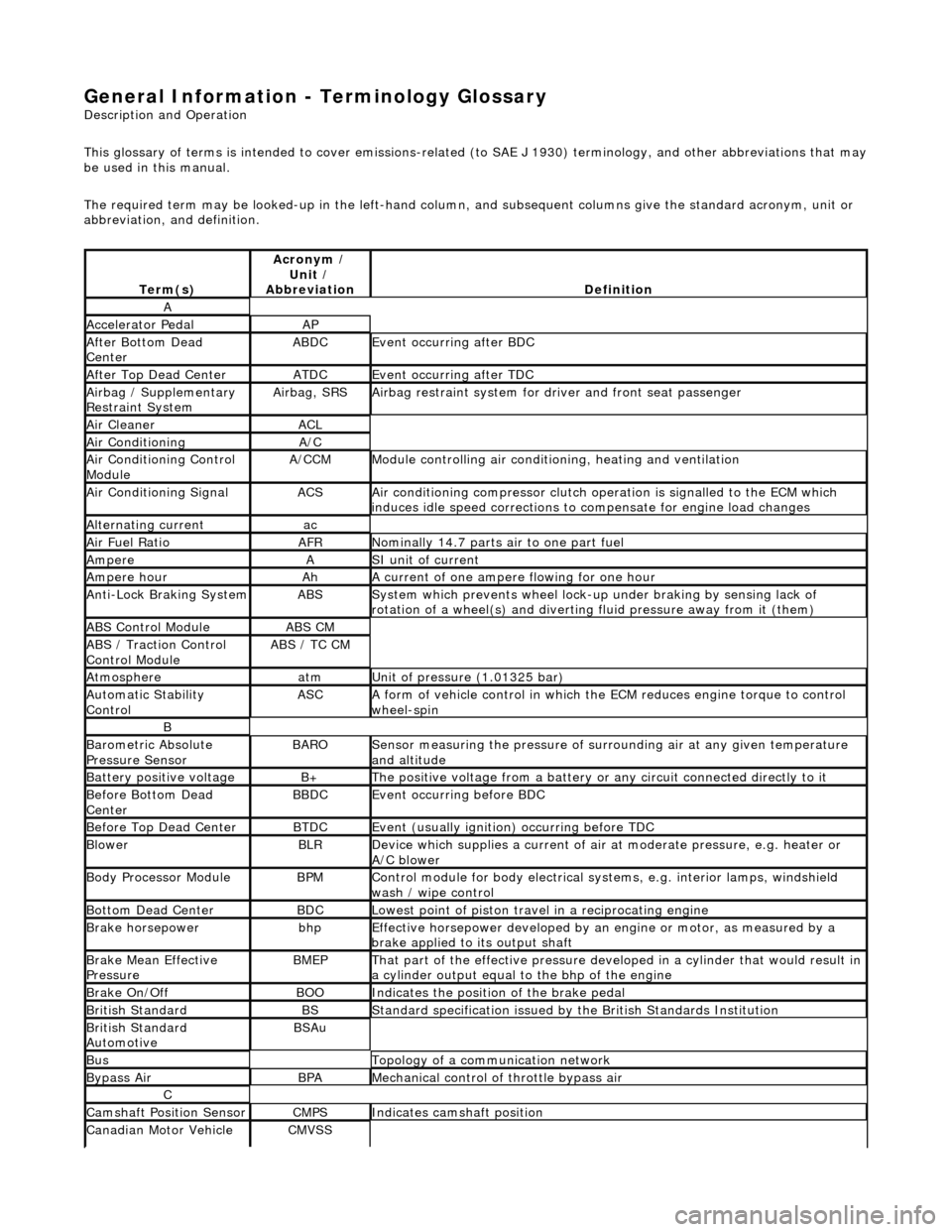
General Information - Terminology Glossary
Description an
d Operation
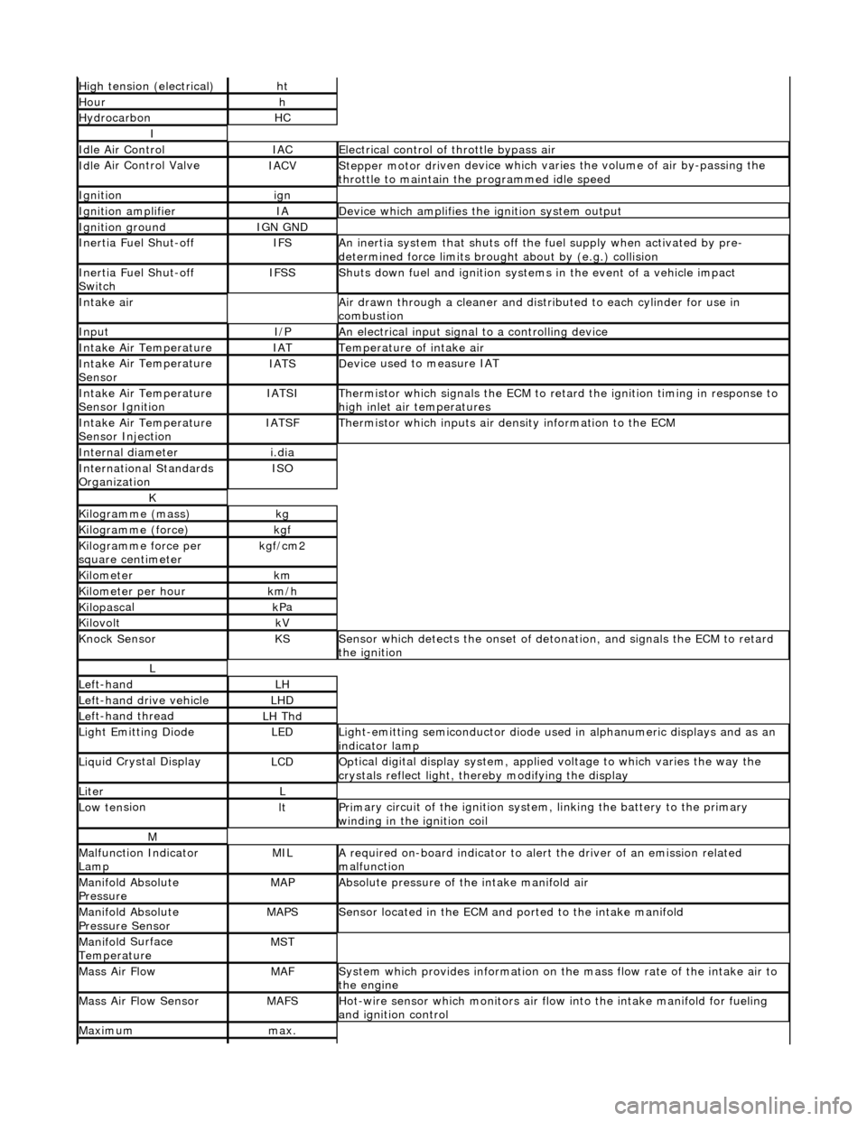
This glossary of terms is intended to cover emissions-related (to SAE J 1930) term inology, and other abbreviations that may
be used in this manual.
The required term may be looked-up in th e left-hand column, and subsequent columns give the standard acronym, unit or
abbreviation, and definition.
Te rm
(s)
Acr
ony
m /
Unit /
Abbreviation
De fi
nition
A
Accel
e
rator Pedal
AP
Af
ter Botto
m Dead
Center
ABDCEvent occurri ng after
BDC
Af
ter Top Dead CenterATDCEvent occurri ng after
TDC
Ai
rbag /
Supplementary
Restraint System
Airbag, SRSAi rbag restraint system for
dr
iver and front seat passenger
Air Cleane rACL
Air ConditioningA/C
Air Conditioning Con t
rol
Module
A/CCMModule c
ontrolling air conditioning, heating and ventilation
Air Conditioning SignalACSA
i
r conditioning compressor clutch operation is signalled to the ECM which
induces idle speed corrections to co mpensate for engine load changes
Alternating cu
rrent
ac
Ai
r Fuel R
atio
AFRN
omi
nally 14.7 parts air to one part fuel
Ampe
reASI unit of current
Ampere hourAhA current of one ampere
fl
owing for one hour
Anti-Lock Braking SystemABSS
y
stem which prevents wheel lock-up
under braking by sensing lack of
rotation of a wheel(s) and divertin g fluid pressure away from it (them)
ABS Control Mo
dule
ABS CM
ABS /
T
raction Control
Control Module
ABS / T
C CM
Atmosph
e
re
atmU
n
it of pressure (1.01325 bar)
Au
to
matic Stability
Control
ASCA form of vehicle
control
in which the ECM reduces en gine torque to control
wheel-spin
B
Baro me
tric Absolute
Pressure Sensor
BAR OSensor measuring the pressure of surr ou
nding air at any given temperature
and altitude
Bat t
ery positive voltage
B+The posi
ti
ve voltage from a battery or
any circuit connected directly to it
Before Bottom Dead
CenterBBDCEvent occurri ng before BD
C
Before Top Dead
Center
BTD
CEvent (usual ly
ignition) occurring before TDC
Blowe
rBLRDe
vice which supplies a current of air at
moderate pressure, e.g. heater or
A/C blower
Body Processor M
odule
BPMControl modu
le
for body electrical systems, e.g. interior lamps, windshield
wash / wipe control
Bott om D
ead Center
BD
CLowest poin t of piston
travel in a reciprocating engine
Brake hors
epowe
r
bhpEffecti
ve horsepower devel
oped by an
engine or motor, as measured by a
brake applied to its output shaft
Brake Mean Effective
Pres sureBME PThat p
art of the effective
pressure developed in a cyli nder that would result in
a cylinder output equal to the bhp of the engine
Brake On/ O
ff
BOOIn
dic
ates the position of the brake pedal
Br
it
ish Standard
BSStan
dar
d specification issued by the British Standards Institution
Br
it
ish Standard
Automotive
BSAu
BusTopology of a commu n
ication network
Bypass
AirBPAMechanica l
control of throttle bypass air
C
Camshaft Posit
i
on Sensor
CMPSIndi
cat
es camshaft position
Canadian Motor
V
ehicle
CMVSS
Page 45 of 2490
High
tension (electrical)
ht
Hourh
Hydro
carbon
HC
I
Idl
e Air Control
IACEl
ectrical control of throttle bypass air
Idl
e Air Control Valve
IACVStepper motor dri
ven device which vari
es the volume of air by-passing the
throttle to maintain the programmed idle speed
Ignitionign
Ignition am
plifier
IAD
evice which amplifies the i
gniti
on system output
Ignition groundIGN GND
In
ertia Fuel Shut-off
IFSAn
inertia system that shuts off the fuel supply when activated by pre-
determined force limits brough t about by (e.g.) collision
In
ertia Fuel Shut-off
Switch
IFSSShut
s down fuel and ignition systems in the event of a vehicle impact
Inta
ke air
Air drawn t
hrough a cleaner and distri
buted to each cylinder for use in
combustion
InputI/PAn
electrical input signal to a controlling device
Inta
ke Air Temperature
IATTem
perature of intake air
Inta
ke Air Temperature
Sensor
IATSDe
vice used to measure IAT
Inta
ke Air Temperature
Sensor Ignition
IATSITherm
istor which signals the ECM to retard
the ignition timing in response to
high inlet air temperatures
Inta
ke Air Temperature
Sensor Injection
IATSFTher
mistor which inputs air density information to the ECM
Internal diameteri.
dia
Inte
rnational Standards
Organization
ISO
K
Kilogramme (mass)kg
Kilogram
me (force)
kg
f
Ki
logramme force per
square centimeter
kg
f/cm2
Kilom
eter
km
Ki
lometer per hour
km
/h
Kilopasc
al
kP
a
KilovoltkV
Knock
Sensor
KSSens
or which detects the onset of detonation, and signals the ECM to retard
the ignition
L
Le
ft-hand
LH
Left-hand drive veh
icle
LHD
Le
ft-hand thread
LH Thd
Ligh
t Emitting Diode
LEDLigh
t-emitting semiconductor diode used
in alphanumeric displays and as an
indicator lamp
Liqu
id Crystal Display
LCDOp
tical digital display system, applied voltage to which varies the way the
crystals reflect light, thereby modifying the display
LiterL
Low ten
sion
ltPrim
ary circuit of the ignition system, linking the battery to the primary
winding in the ignition coil
M
Malfu
nction Indicator
Lamp
MILA
required on-board indicator to aler
t the driver of an emission related
malfunction
Mani
fold Absolute
Pressure
MAPAbsolute pressure o
f the intake manifold air
Mani
fold Absolute
Pressure Sensor
MAPSSensor loca
ted in the ECM and
ported to the intake manifold
Manifol
d Surface
Temperature
MST
Mass Ai
r Flow
MAFSy
stem which provides inform
ation on the mass flow rate of the intake air to
the engine
Mass Ai
r Flow Sensor
MAFSHot-wi
re sensor which monitors air flow
into the intake manifold for fueling
and ignition control
Maxim
um
max.
Page 54 of 2490
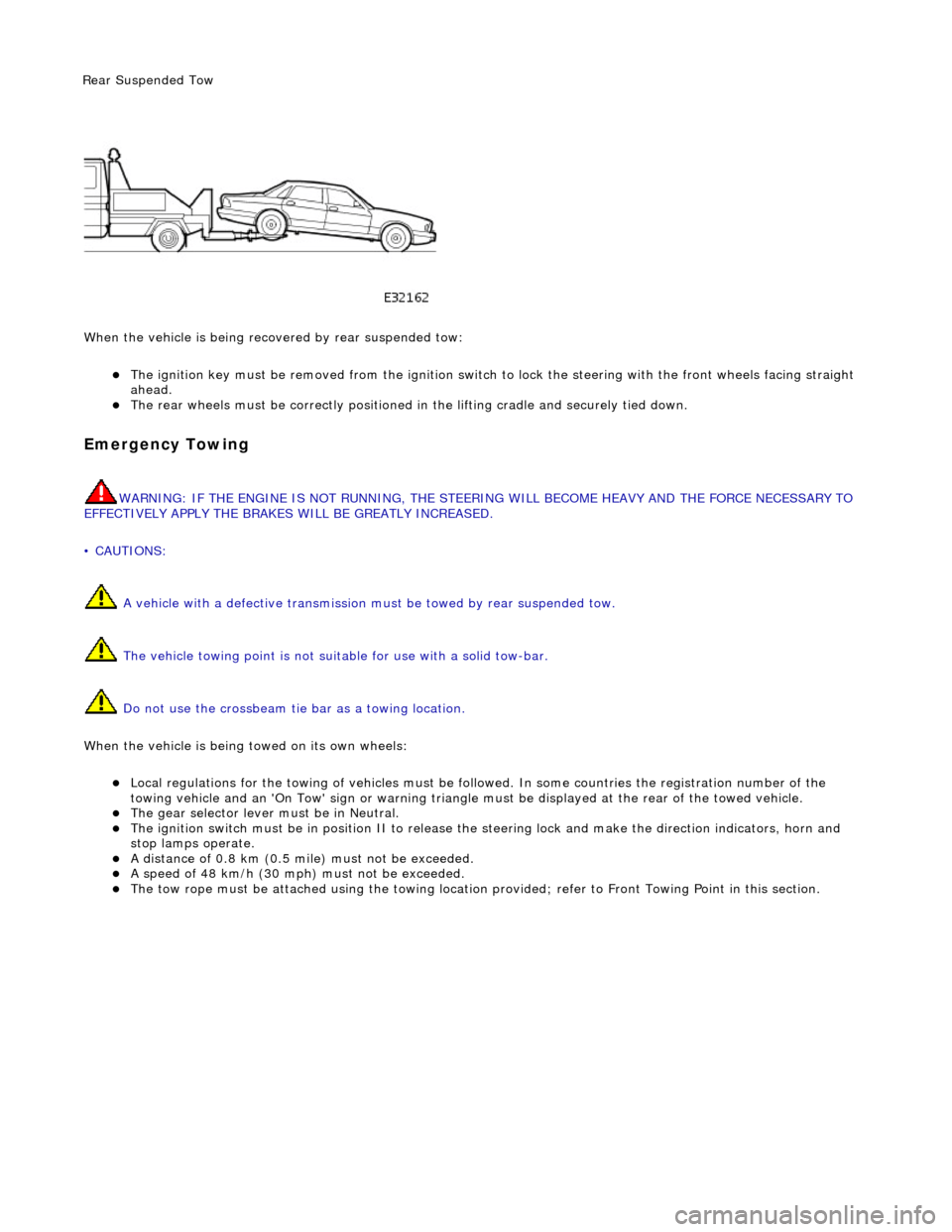
Wh en t
he vehicle is being reco
vered by rear suspended tow:
The ignition key must be remo ved from the ig
nition switch to lock the stee
ring with the front wheels facing straight
ahead.
The re ar
wheels must be
correctly positioned in the lifting cradle and securely tied down.
Em
ergency Towing
WARNING: IF THE
ENGINE IS NOT
RUNNING, THE STEERING WILL BECOME HEAVY AND THE FORCE NECESSARY TO
EFFECTIVELY APPLY THE BRAKES WILL BE GREATLY INCREASED.
• CAUTIONS:
A vehicle with a defective transmission must be towed by rear suspended tow.
The vehicle towing point is not suit able for use with a solid tow-bar.
Do not use the crossbeam tie bar as a towing location.
When the vehicle is being towed on its own wheels:
Loc a
l regulations for the towing of ve
hicles must be followed. In some co untries the registration number of the
towing vehicle and an 'On Tow' sign or warning triangle must be displayed at the rear of the towed vehicle.
The gear s
elector lever
must be in Neutral.
The
ignition switch must be in positi
on II to release the steering lock and make the direction indicators, horn and
stop lamps operate.
A di
stance of 0.8 km (0.5 mi
le) must not be exceeded.
A spe
ed of 48 km/h (30 mph) must not be exceeded.
The tow rope must be attached using th
e towi
ng location provided; refer to Front Towing Point in this section.
Rear Su
spended
Tow
Page 432 of 2490
It is a reciprocating two
-circuit pu
mp in which one brake circuit is as signed to each pump circuit.
It supplies th
e fluid pressure and vo
lume to supply the brake circuits under ABS and Traction control.
The pump is driven by an electri
c motor, with the pump
housing incorporating two lo w pressure accumulators and
damping chambers for each brake circuit.
The ac cu
mulator stores the pressure and smooths out the output pu
lses from the pump.
ABS Warning Lamp
The sys
tem will be set in a fail-safe mode if a problem is de
tected; a warning lamp on the instrument panel will notify the
driver there is a problem.
Anti-Lock Braking Sy
stem (ABS)
The AB
S components are combined with
an hydraulic booster and a tandem master cylinder to provide a two circuit braking
system. The system comprises, four wheel speed sensor s, a brake control modulator and an ABS warning lamp.
Should a wheel start to lock-up during braking a signal tr ansmitted from the wheel speed sensor to the brake control
modulator will start the hydraulic pump. The brake control modula tor will close the input valve of the line connected to the
locked-wheel to stop any increase in fluid pressure to the br ake caliper. If this fails to prevent the wheel locking, the
pressure in the caliper will be decreased by opening the return valve until th e wheel starts accelerating again. The fluid
pressure from the return va lve is directed into the low pressure accumulator, housed in the pump.
From the low pressure accumulator, fl uid is pumped through the damping cham ber to the brake master cylinder. The
pressure to the brake caliper will then be increased in small steps to maintain maximum adhesion between the tire and road
surface. This is achieved by closing the return valve, and opening the input valve and using the hydraulic pump to increase
the pressure.
Although the system senses all four wheels independently, the rear wheels are regulated as a pair. If a sensor on a rear
wheel detects a wheel decelerating rapidly, then the fluid pressure to both wheels is reduced. The fluid pressure is then
dictated by the wheel having the lowe st adhesion with the road surface.
The ABS system will be set in a fail-safe mode if a problem is detected; a warn ing lamp on the instrument panel will notify
the driver there is a problem. The brake system will still operate conventionally and with the same standard of performance
as a vehicle not equipped with ABS.
Automa tic Stability Control (ASC)
Th
e ASC utilizes the ABS sensing arrangement to provide the maximum traction force to propel the vehicle.
The ASC is switched on when the engine is started. The system can be switched off by pressing the 'ASC OFF' (the switched
is marked 'TRAC OFF' on vehicles fitted with traction control). The switch, which is situated in the center console switchpack,
lights up to warn that the system is sw itched off. An 'ASC' amber warning light flashes on the instrument panel when the
system detects a spinning wheel.
The ASC system uses engine intervention to reduce the torque delivered to the drive wheels to prevent them spinning.
Engine torque is re duced in three ways:
The
throttle is moved towards the closed position.
The ignition is retarded. F
u
el is cut-off at the cylinder injectors.
Wheel spin is detected by the wheel sp eed sensors and communicated to the AB S/TCCM. The ABS/TCCM uses information
from the controller area network (CAN) to calculate the torque that the engine should produce to stop the wheel spinning.
Torque reductions are then requested from the engine control module (ECM ) through the CAN. The throttle is then
positioned to provide the target torque, which has been calculated to prevent wheel spin. During the transient phase of
torque reduction the fuel is cut-off and th e ignition retarded Both the fuel cut-off an d ignition retard will be restored to
normal when the throttle is set to its new position.
The ASC uses a brake control modulator with six solenoid va lves: three normally open inlet valves and three normally
Page 436 of 2490
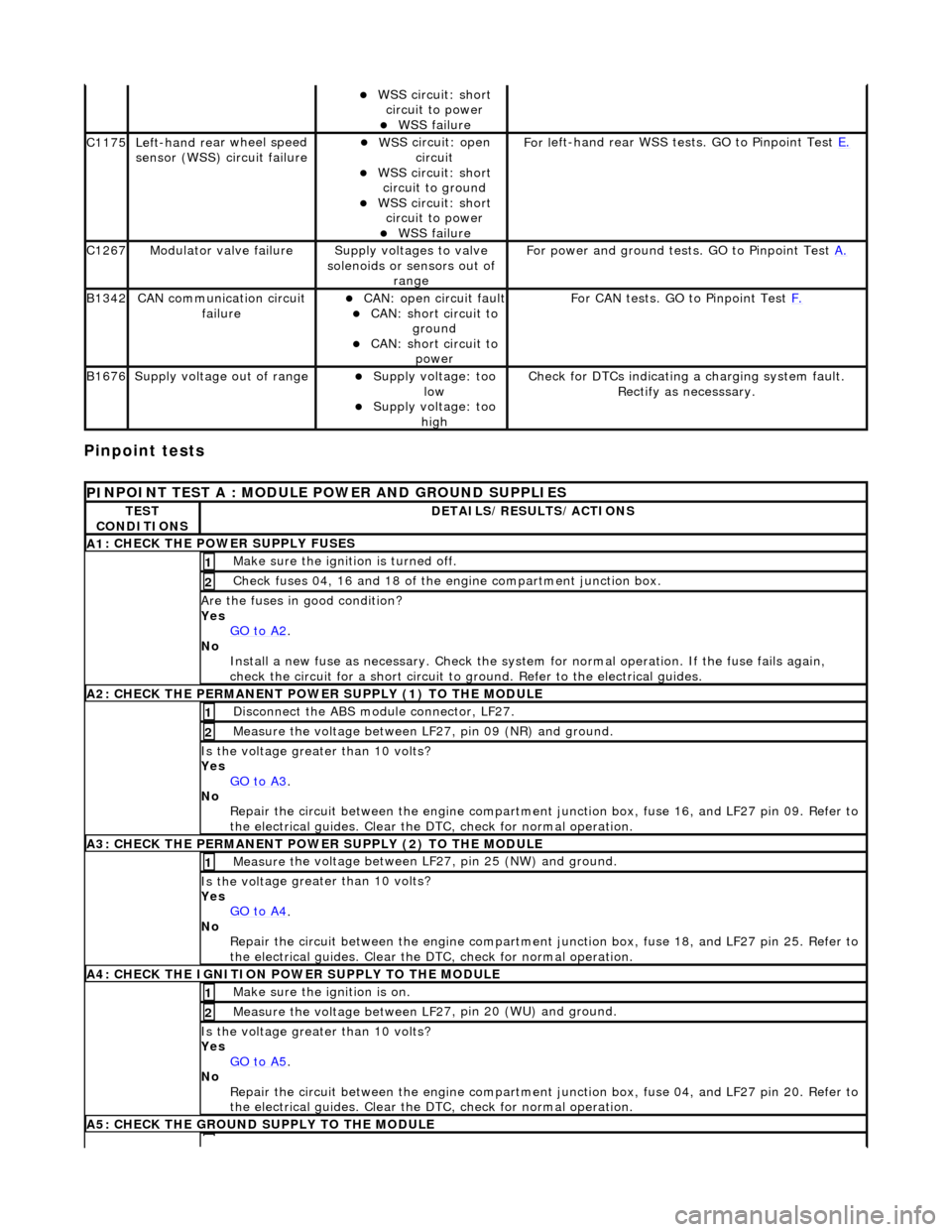
Pinpoint tests
W
S
S circuit: short
circuit to power
WSS f
ailure
C1
175Left -hand re
ar wheel speed
sensor (WSS) circuit failure
W S
S circuit: open
circuit
WS
S circuit: short
circuit to ground
W S
S circuit: short
circuit to power
WSS f
ailure
F
or l
eft-hand rear WSS test
s. GO to Pinpoint Test E.
C1267Modulat or valv
e failure
Supply volt
ages
to valve
solenoids or sensors out of range
Fo
r power and ground tests. GO to Pinpoint Test
A.
B1342CAN co
mmunication circuit
failure
CAN :
open circuit fault
CAN:
short circuit to
ground
CAN :
short circuit to
power
Fo
r CAN tests. GO to Pinpoint Test
F.
B1676Supply volt
age out of range
Supply voltage:
too
low
Supply volt age:
too
high
Check fo
r DTCs indicating a charging system fault.
Rectify as necesssary.
PI
NPOINT TEST A : MODULE
POWER AND GROUND SUPPLIES
TES
T
CONDITIONS
D E
TAILS/RESULTS/ACTIONS
A
1
: CHECK THE POWER SUPPLY FUSES
Make sure the igniti
on is turned off. 1
Chec
k fuses 04, 16 and 18 of the engine compartment junction box.
2
Are th
e fus
es in good condition?
Yes GO to A2
.
No
Install a new f
use as
necessary. Check the syst em for normal operation. If the fuse fails again,
check the circuit for a short circuit to ground. Refer to the electrical guides.
A2: CHECK THE PERMANENT
POWER SUPPLY (1) TO THE MODULE
Disc
onnect the ABS module connector, LF27.
1
Measure the voltage between LF
2
7, pin 09 (NR) and ground.
2
Is the vol
t
age greater than 10 volts?
Yes GO to A3
.
No Re
pair the circuit between the engine compartment
junction box, fuse 16, and LF27 pin 09. Refer to
the electrical guides. Clear the DTC, check for normal operation.
A3: CHECK THE PERMANENT
POWER SUPPLY (2) TO THE MODULE
Meas
ure t
he voltage between LF27, pin 25 (NW) and ground.
1
Is the vol
t
age greater than 10 volts?
Yes GO to A4
.
No
Re
pair the circuit between the engine compartment ju
nction box, fuse 18, and LF27 pin 25. Refer to
the electrical guides. Clear the DTC, check for normal operation.
A4: CHECK
THE IGNITION POWER SUPPLY TO THE MODULE
Make sure the ignition is on. 1
Measure the
voltage between LF 2
7, pin 20 (WU) and ground.
2
Is the vol
t
age greater than 10 volts?
Yes GO to A5
.
No Re
pair the circuit between the engine compartment ju
nction box, fuse 04, and LF27 pin 20. Refer to
the electrical guides. Clear the DTC, check for normal operation.
A5: CHECK
THE GROUND SUPPLY TO THE MODULE
Page 460 of 2490
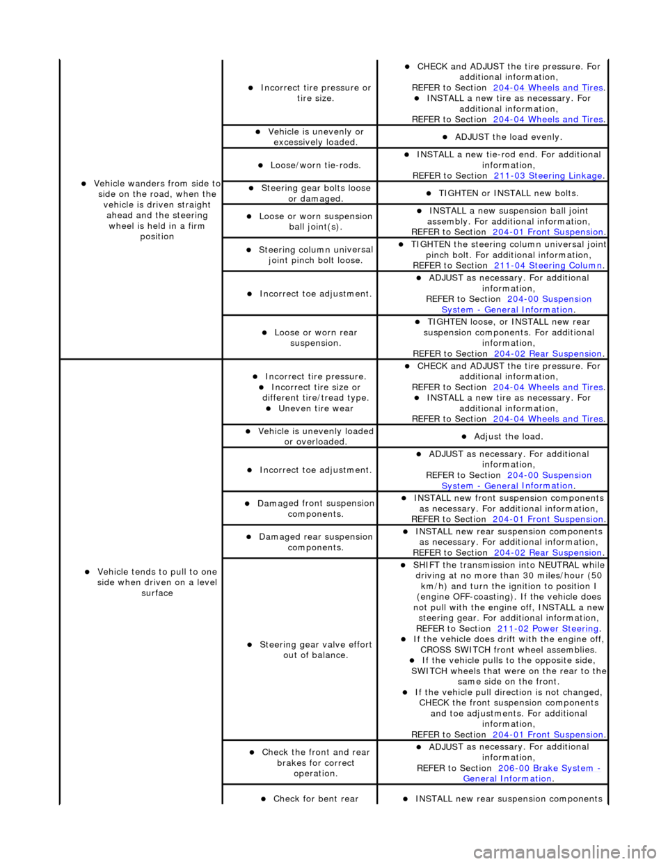
Vehicl
e wanders from side to
side on the road, when the vehicle is driven straight ahead and the steering wheel is held in a firm position
Incorrect ti re
pressure or
tire size.
CHECK and ADJ
UST the tire pressure. For
additional information,
REFER to Section 204
-0 4
Wheels and Tires
. IN
ST
ALL a new tire as necessary. For
additional information,
REFER to Section 204
-0 4
Wheels and Tires
.
Vehi
cl
e is unevenly or
excessively loaded.
A D
JUST the load evenly.
Loose/worn ti
e-
rods.
INST
ALL a ne
w tie-rod
end. For additional
information,
REFER to Section 211
-0 3
Steering Linkage
.
Steeri
ng gear bolts loose
o
r damaged.
TIGHTE
N or INSTALL
new bolts.
Loose or worn suspensi
on
ball jo
int(s).
INST
ALL a ne
w suspension ball joint
assembly. For additional information,
REFER to Section 204
-01 Fron
t Suspension
.
Steeri
ng column uni
versal
joint pinch bolt loose.
TI G
HTEN the steering column universal joint
pinch bolt. For additi onal information,
REFER to Section 211
-0 4
Steering Column
.
Incorre
ct
toe adjustment.
ADJUS
T as necessary. For additional
information,
REFER to Section 204
-00 Sus
pension
Sy
ste
m
- General
Information
.
Loose or worn rear
susp
ension.
TIGHTEN
loose, or IN
STALL new rear
suspension components. For additional information,
REFER to Section 204
-0 2
Rear Suspension
.
Vehicle t
e
nds to pull to one
side when driven on a level surface
Incorrect ti
re pressure.
Incorrect
ti
re size or
different tire/tread type.
Uneven tire wear
CHECK and ADJ
UST the tire pressure. For
additional information,
REFER to Section 204
-0 4
Wheels and Tires
. IN
ST
ALL a new tire as necessary. For
additional information,
REFER to Section 204
-04
Wheels and Tires
.
Vehicl
e is unevenly loaded
or overloaded.
Adjust the load
.
Incorre
ct
toe adjustment.
ADJUS
T as necessary. For additional
information,
REFER to Section 204
-00 Sus
pension
Sy
ste
m
- General
Information
.
Dam
a
ged front suspension
components.
I N
STALL new front suspension components
as necessary. For addi tional information,
REFER to Section 204
-01 Fron
t Suspension
.
Damaged rear
suspen
sion
components.
INST ALL ne
w rear suspension components
as necessary. For addi tional information,
REFER to Section 204
-0 2
Rear Suspension
.
Steeri
ng gear val
ve effort
out of balance.
SHIF T the
transmission into NEUTRAL while
driving at no more than 30 miles/hour (50 km/h) and turn the ignition to position I
(engine OFF-coasting). If the vehicle does
not pull with the engine off, INSTALL a new steering gear. For additional information,
REF E
R to Section 211
-0
2
Power Steering
. If t
he
vehicle does drift with the engine off,
CROSS SWITCH front wheel assemblies.
If the
vehicle pulls to
the opposite side,
SWITCH wheels that were on the rear to the
same side on the front.
If the v
ehicle pull dire
ction is not changed,
CHECK the front susp ension components
and toe adjustments. For additional information,
REFER to Section 204
-01 Fron
t Suspension
.
Chec
k
the front and rear
brakes for correct operation.
ADJUS
T as necessary. For additional
information,
REFER to Section 206
-0 0
Brake System
-
General Informati on.
Check fo
r bent rear
INST
ALL ne
w rear suspension components
Page 469 of 2490
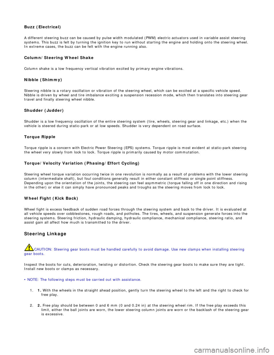
Buzz (E
lectrical)
A
different steering buzz can be caused by
pulse width modulated (PWM) electric actuators used in variable assist steering
systems. This buzz is felt by turning the ignition key to run without starting the engine and holding onto the steering wheel.
In extreme cases, the buzz can be felt with the engine running also.
Column/Steering Wheel
Shake
Column shake is a low f
requenc
y vertical vibration excited by primary engine vibrations.
Nibble (Shimm
y)
Steeri
ng nibble is a rotary oscillation or
vibration of the steering wheel, which can be excited at a specific vehicle speed.
Nibble is driven by wheel and tire imbalance exciting a suspensi on recession mode, which then translates into steering gear
travel and finally steering wheel nibble.
Shudder (Judd
er)
Shudder i
s a low frequency oscillation of th
e entire steering system (tire, wheels, st eering gear and linkage, etc.) when the
vehicle is steered during static-park or at low sp eeds. Shudder is very dependent on road surface.
Torque Ri
pple
Torque rippl
e is a concern with Electric Power Steering (EPS) sy
stems. Torque ripple is most evident at static-park steering
the wheel very slowly from lock to lock. Torque ripple is primarily caused by motor commutation.
Torque/Veloc
ity Variation
(Phasing/Effort Cycling)
Steeri
ng wheel torque variation oc
curring twice in one revolution is normally as a result of problems with the lower steering
column (intermediate shaft), but foul cond itions generally result in either constant stiffnes s or single point stiffness.
Depending upon the orientation of the joints, the steering can fe el asymmetric (torque falling off in one direction and rising
in the other) or else it can simply have pronounced peaks and troughs as the steering moves from lock to lock.
Wheel Fight
(Kick Back)
W
heel fight is excess feedback of sudden road forces through th
e steering system and back to the driver. It is evaluated at
all vehicle speeds over cobblestones, rough roads, and potholes . The tires, wheels, and suspension generate forces into the
steering systems. Steering friction, hydraulic damping, hydr aulic compliance, mechanical compliance, steering ratio, and
assist gain all affect how much is transmitted to the driver.
Stee
ring Linkage
CAUTI
ON: Steering gear boots must be
handled carefully to avoid damage. Use new clamps when installing steering
gear boots.
Inspect the boots for cuts, deterioration, tw isting or distortion. Check the steering gear boots to make sure they are tight.
Install new boots or clamps as necessary.
• NOTE: The following steps must be carried out with assistance.
1. 1. With the wheels in the straight ahead po sition, gently turn the steering wheel to the left and the right to check for
free play.
2. 2. Free play should be between 0 and 6 mm (0 and 0.24 in) at the steering wheel rim. If the free play exceeds this
limit, either the ball joints are worn, the lower steering column joints are worn or the backlash of the steering gear
is excessive.
Page 516 of 2490
IGNITION.
All circuits, except the star
ter motor, are activated. The key rema ins in this position when driving.
Position 'III'
START. The starter operates for as long as the key is held in this position, ag ainst spring pressure. If the engine fails to
start, the key must be returned to position 'I' befo re another start is attempted.
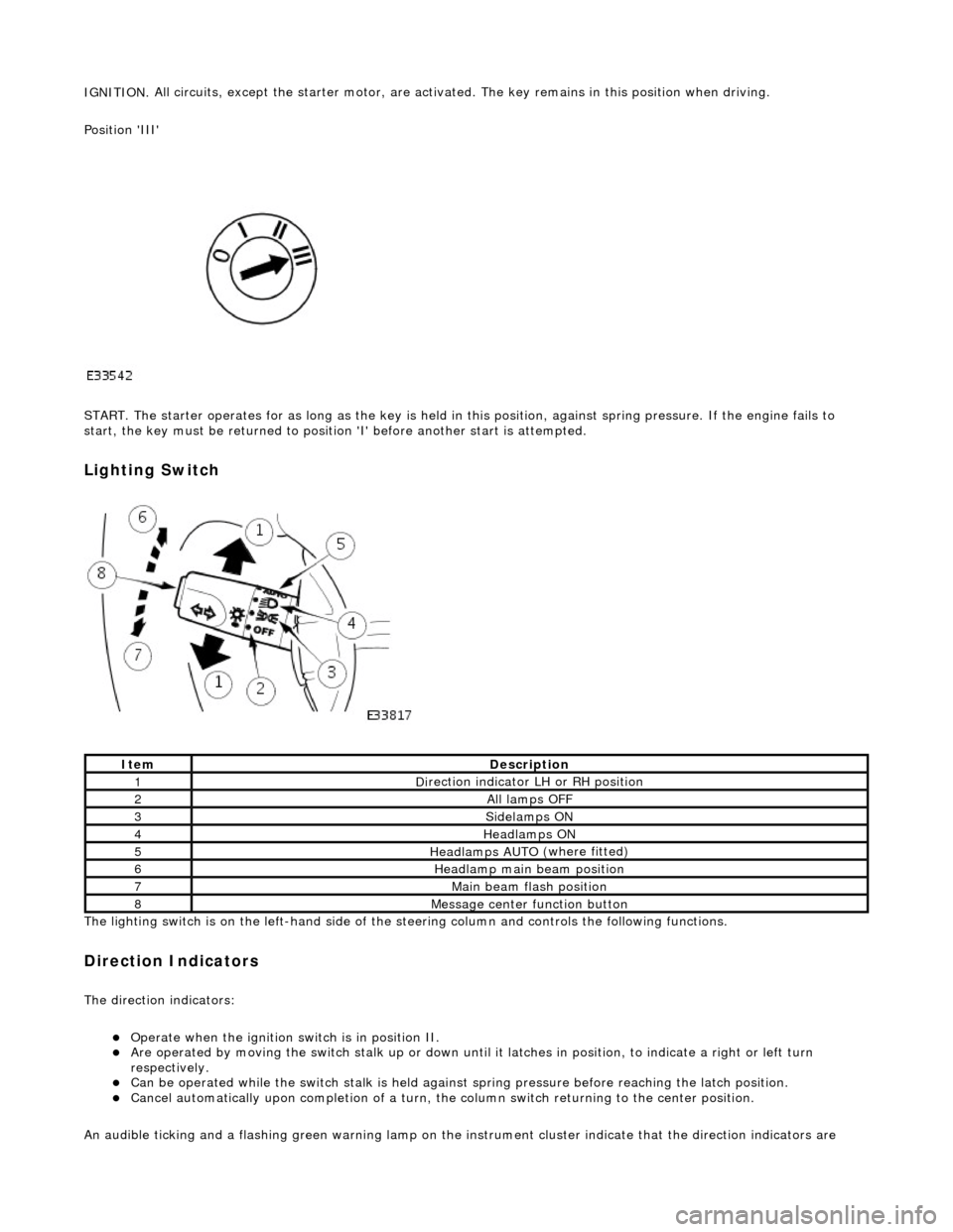
Lighting Switch
The li
ghting switch is on the left-h
and side of the steering column and controls the following functions.
Direction Indicators
The direction in
dicators:
Operate
when the ignition switch is in position II.
Are operat
ed by movi
ng the switch stalk up or down until it latches in position, to in
dicate a right or left turn
respectively.
Can be o p
erated while the switch stalk is held against
spring pressure before reaching the latch position.
Cancel
automatically upon completion of a turn, the
column switch returning to the center position.
An audible ticking and a flashing green warning lamp on the in strument cluster indicate that the direction indicators are
Ite
m
De
scr
iption
1D
i
rection indicator LH or RH position
2All lamps OFF
3Side
lamps ON
4Headlamps ON
5Headlamps AUT O
(where fitted)
6He
adlam
p main beam position
7Mai
n
beam flash position
8M
e
ssage center function button
Page 522 of 2490
diverter val
ve (if fitted) and oil filter.
Main
bearings
which are grooved in the upper positions and plain in
the lower positions. They are manufactured from
aluminium / tin material.
A c
rankshaft with under
cuts and rolled fillets for extra strength.
Fracture
-split connecting rods in sintered-forged steel.
Brackets
bolted to the front of
the cylinder
block are used to mo unt all accessories.
A sin
gle, seven ribbed vee belt
drives the accessories.
An au
tomatic belt tensioner for the front accessory drive,
incorporating a wear indicator.
An advanced en
gine management system inco
rporating electronic throttle control.
The un
it meets the requirements of the CARB OBDII USA legislation.
Ancillary Systems
The an
ci
llary systems, driven by the engine, each have a
detailed Description and Operation along with Diagnostic
Procedures, and Removal and Installation instructions ; refer to the following sections of this manual:
Power Steeri
ng Pump - Section 211-02
Ai
r Conditioning Compressor - Sectio
n 412-03
Engine
C
ooling Pump - Section 303-03
Generator
- Sectio
n 414-02
The drive belt, idler pulley and automatic tensioner are described in Section 303-05.
The engine starting system is described in Section 303-06.
En
gine Management and Emission Control System
Engine Control Modu
le (ECM)
Engine
management and exhaust emissions are controlled by the ECM, which has the
following main functions:
Fu
el injection
Idle
s
peed
Ignition Ev
aporative loss system
Engine
cooling fans Clim
ate control compressor clutch demand
The microprocessor within the ECM receiv es signals from various sensors and other modules and uses a pre-determined
program to compute engine management functions.
Adaptive functions are incorporated in the ECM to cater for co ntinuous adjustments to its computations to suit prevailing
conditions. Because the system also controls emissions to suit all modes, neither CO levels nor idle speed require service
attention or adjustment, except if an error should occur.
On Board Diagnostics are controlled by the ECM with the continuous monitoring of incoming signals and the subsequent
verification against what the module expects to 'see'. Should a si gnal be incorrect or missing, the ECM will substitute a fixed
value to provide the 'limp home mode' and alert the driver of the problem. Fixed values may be adopted for:
Transmission oil
temperature
Mechanica
l
guar
d position
Throttle blade angle Camshaft position
Inta
k
e air temperature
Diagnostic trouble codes (DTC), including OBD II codes, are stored in the ECM memo ry and can be read by an appropriate
retrieval tool.
Should either the ECM or TCM fa il, ensure that the control housing cooling fan is operating correctly. Failure of the cooling
fan MUST be rectified before renewing a control module and details of a fa n failure should accompany a returned control
module.