rear axle JAGUAR X308 1998 2.G Workshop Manual
[x] Cancel search | Manufacturer: JAGUAR, Model Year: 1998, Model line: X308, Model: JAGUAR X308 1998 2.GPages: 2490, PDF Size: 69.81 MB
Page 3 of 2490

Rear Toe Adjustment (57.65. 08)
Whee
l
Bearing Circlip Inspection
Wheel Bearing Inspection
204‐01: Front Suspension
Specification
Description and Operation
Front Suspension
Removal and Installation
Ball Joint (60.15.02)
Rear Lower Arm (60.35.54)
Rear Lower Arm Bushing (60.35.56)
Front Shock Absorber (60.30.04)
Spring
Spring Seat (60.20.03)
Front Sta
bilizer Bar (60.10.01)
Front Stabilizer Bar Bushing (60.10.04)
Front Stabilizer Bar Link (60.10.02)
Upper Arm Bushing
Front Wheel Bearing (60.25.40)
Wheel Hub
Wheel Knuckle (60.25.23)
Wheel Knuckle and Wheel Hub Assembly (60.25.38.90)
Wheel Knuckle and Wheel Hub Assembly Conversion (60.25.43)
204‐02: Rear Suspension
Specif
ication
Description and Operation
Rear Suspension
Removal and Installation
Axle Bump Stop (64.30.15)
Rear Suspension and Axle Assembly (64.25.01)
Rear Shock Absorber (64.30.02)
Shock Absorber Lower Bushing (64.30.39)
Spring (64.20.01)
Rear Stabilizer Bar (64.35.08) ‐ 4.0L SC V8 ‐ AJ26
Rear Stabilizer Bar Bushing (64.35.18) ‐ 4.0L SC V8 ‐ AJ26
Page 4 of 2490

Stabilizer Bar Mount i
ng
Frame (64.25.12)
Stabilizer Bar Mounting Frame Bushing (64.25.13)
Rear Wheel Bearing (64.15.14)
Wheel Hub Seal (64.15.15)
Wheel Knuckle Bushing (64.15.24)
204‐04: Wheels and Tires
Specification
Description and Operation
Wheels and Tires
Diagnosis and Testing
Wheels and Tires
Removal and Installation
Whee
l and Tire (74.20.05)
204‐05: Vehicle Dynamic Suspension
Description and Operation
Vehicle Dynamic Suspension
Diagnosis and Testing
Vehicle Dynamic Suspension
205: Driveline
205‐00: Driveline System ‐ General Information
Description and Operation
Driveline System
205‐01: Driveshaft
Specification
Description and Operation
Drives
haft
Removal and Installation
Driveshaft (47.15.01)
205‐02: Rear Drive Axle/Differential
Specification
Description and Operation
Page 5 of 2490

Rear Drive Axle and Diffe rential
General Procedures
Differential Output Shaft End Float Check (51.10.24)
In‐Vehicle Repair
Axle Shaft (47.10.01)
Differential Output Shaft Bearing (51.10.22)
Drive Pinion Flange and Drive Pinion Seal (51.20.01)
Removal and Installation
Axle Assembly (51.25.13)
206: Brake System
206‐00: Brake System ‐ Gen
eral Information
Specification
Description and Operation
Brake System
Diagnosis and Testing
Brake System
General Procedures
Brake System Bleeding (70.25.03) ‐ Vehicles With: Standard Brakes
Brake System Bleeding (70.25.03) ‐ Vehicles With: High Performance Brakes
Front Brake Disc Runout Check ‐ Vehicles With: Standard Brakes
Front Brake Disc Runout Chec
k ‐ Vehicles With: High Performance Brakes
Rear Brake Disc Runout Check (70.12.36) ‐ Vehicles With: Standard Brakes
Rear Brake Disc Runout Check (70.12.36) ‐ Vehicles With: High Performance
Brakes
206‐03: Front Disc Brake
Specification
Description and Operation
Front Disc Brake
Removal and Installation
Brake Caliper (70.55.02) ‐ Vehicles With: Standard Brakes
Brake Caliper (70.55.02) ‐ Vehicles With: High Perfo
rmance Brakes
Brake Disc (70.10.10) ‐ Vehicles With: Standard Brakes
Brake Disc (70.10.10) ‐ Vehicles With: High Performance Brakes
Brake Pads (70.40.02) ‐ Vehicles With: Standard Brakes
Page 34 of 2490

501‐20B : Supp l
emental
Restraint System
Specification
Description and Operation
Air Bag Supplemental Restraint System (SRS)
Removal and Installation
Air Bag Control Module (76.73.41)
Driver Air Bag Module (76.73.39)
Passenger Air Bag Module (76.73.37)
Side Air Bag Module (76.73.47)
Side Impact Sensor (76.73.53)
501‐25: Body Repairs ‐ Genera
l Information
Description and Operation
Body Repairs
502: Frame and Mounting
502‐00: Uni ‐Body, Subframe and Mounting System
Removal and Installation
Front Axle Crossmember
Front Axle Crossmember Front Bushing (60.35.24)
Front Axle Crossmember Front Bushing Heat Shield (60.35.37)
Front Axle Crossmember Rear Bushing (
60.35.26)
Rear Axle Crossmember (64.25.16)
Rear Axle Crossmember Bushing (64.25.02)
Page 49 of 2490
Identification
Codes -
Identification Codes
Descr
iption and Operation
En
gine Number
The en
gine number (10 digits) is stamped on a raised pad on th
e front of the engine block near the thermostat housing. The
piston grade reference (8 digits) is also shown.
Automatic Transmission
Number
The
serial number of the transmission unit is displayed on
a metal or bar code label attached to the LH side of the
transmission casing.
Veh
icle Identification
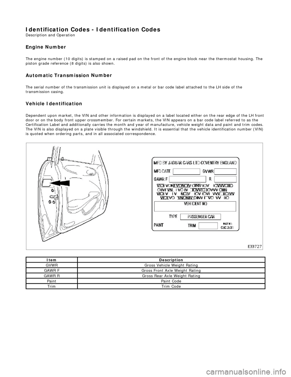
Dependent
upon market, the VIN and other info
rmation is displayed on a label located ei ther on the rear edge of the LH front
door or on the body front upper crossmember. For certain mark ets, the VIN appears on a bar code label referred to as the
Certification Label and additionally carries the month and year of manufacture, vehicle weight data and paint and trim codes.
The VIN is also displayed on a plate visible through the windshie ld. It is essential that the vehicle identification number (VIN)
is quoted when ordering parts, and in all associated correspondence.
ItemDe
scription
GVW
R
G
ross Vehicle Weight Rating
GAW
R F
Gros
s Front Axle Weight Rating
GAW
R R
Gros
s Rear Axle Weight Rating
Pai
nt
Pai
nt Code
TrimTrim
Code
Page 50 of 2490
Date of
Manufacture
T
h
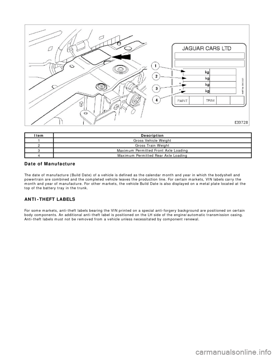
e date of manufacture (Build Date) of a vehicle is define
d as the calendar month and year in which the bodyshell and
powertrain are combined and the completed vehicle leaves the production line. For certain markets, VIN labels carry the
month and year of manufacture. For other markets, the vehicle Build Date is also displayed on a metal plate located at the
top of the battery tray in the trunk.
ANTI-T
HEFT LABELS
F
or
some markets, anti-theft labels bearing the VIN printed on
a special anti-forgery background are positioned on certain
body components. An additional anti-theft label is positioned on the LH side of the engine/automatic transmission casing.
Anti-theft labels must not be removed from a vehicle unless necessitated by component renewal.
ItemDe scrip
tion
1Gross Vehic
l
e Weight
2Gross Trai
n W
eight
3Maxim
u
m Permitted Front Axle Loading
4Maxim
u
m Permitted Rear Axle Loading
Page 166 of 2490

Rear Su
spension -
Lubric
ants, Fluids, Sealants and Adhesives
Torques
UnitSp
ecification
Loctite27
0
Greas eShell Retin a
x 'A'
Greas
eCastro l 'NT
R'
Com
p
onent
Nm
N
u
t - hub to axle shaft
3
04 -
336
Nu
t -
hub carrier pivot pin
88
-
118
Bol
t
- ABS sensor to hub carrier
8-1
0
Nu
t - stabilizer bar link to lower wishbone.
30
-40
Nu
t - stabilizer bar to link assembly.
30
-40
Bolts -
monostrut to body mounting brackets
88
-
118
Bolt
s
- monostrut to wishbone tie assembly
77
-
103
Bolts
- bu
mp stop to body
26
-34
Bol t
- damper lower mounting
80
-
100
N
u
t - damper top
31
-39
Bolts -
damper mounting plate to body
17
-23
Page 168 of 2490
Each r
oad spring and is located between the wishbone in
tegral spring seat and the body suspension turret.
Each shoc
k absorber unit is installed
co-axially within the road spring.
The lo
wer end of each shock absorber is secured to the
wishbone by a bolt which also functions as a pivot.
Adaptive damping is av
ailable as an option.
A
rear stabi
lizer bar is installed on
Supercharged and Sport Suspension models . Mounted at the rear of the wishbone
tie assembly, the stabilizer bar is connected to the wishbone by short links.
Op era
tion
As each road wheel r
i
ses, move
ment is transmitted through th e hub carrier assembly to the wishbone and axle shaft. The
corresponding rise of the wishbone compre sses the road spring and partially telescopes the shock absorber. During this
action, the spring absorbs result ing shocks and the shock absorber minimizes spring oscillation.
During cornering, vehicle weight is transferred to the outer road wheel with a resulting tendency for the inner wheel to lift.
On Supercharged and Sport Suspension vehicl es, a rear stabilizer bar assists in minimizing this tendency by transferring a
proportion of potential lift of the inner wheel to the outer wheel. This results in enhanced body stability with improved
cornering capabilities.
Page 169 of 2490
Rear Suspension - Axle B
ump Stop
Re
moval and Installation
Remov
al
CAUTI
ON: Replacement of
nuts and bolts: Various thread-locking devices are used on nuts and bolts throughout the
vehicle. These devices restrict the number of times a nut or bolt can be used. See section 100-00 for information.
I
nstallation
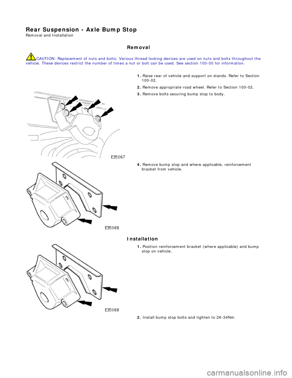
1.
R
aise rear of vehicle and support
on stands. Refer to Section
100-02.
2. Remove appropriate road wheel. Refer to Section 100-02.
3. Remove bolts securing bump stop to body.
4. Remove bu
mp stop and where applicable, reinforcement
bracket from vehicle.
1. Position reinforcemen t brac
ket (where a
pplicable) and bump
stop on vehicle.
2. Install bump stop bolts and tighten to 26-34Nm.
Page 171 of 2490
Rear
Suspension - Rear Susp
ension and Axle Assembly
Re
moval and Installation
Remov
al
1.
CAUTI
ON: Replacement of nuts and bolts: Various
thread-locking devices are used on nuts and bolts throughout the
vehicle. These devices restrict the number of times a nut or bolt
can be used.
For additional informat ion, refer to Section 100
-0
0 General
Informati
on
.
R
aise the rear of the vehicle
and support on axle stands.
For additional informat ion, refer to Section 100
-0
2 Jacking and
Liftin
g
.
2.
R
emove the rear wheels.
For additional informat ion, refer to Section 204
-04
Wheels and
Tire
s
.
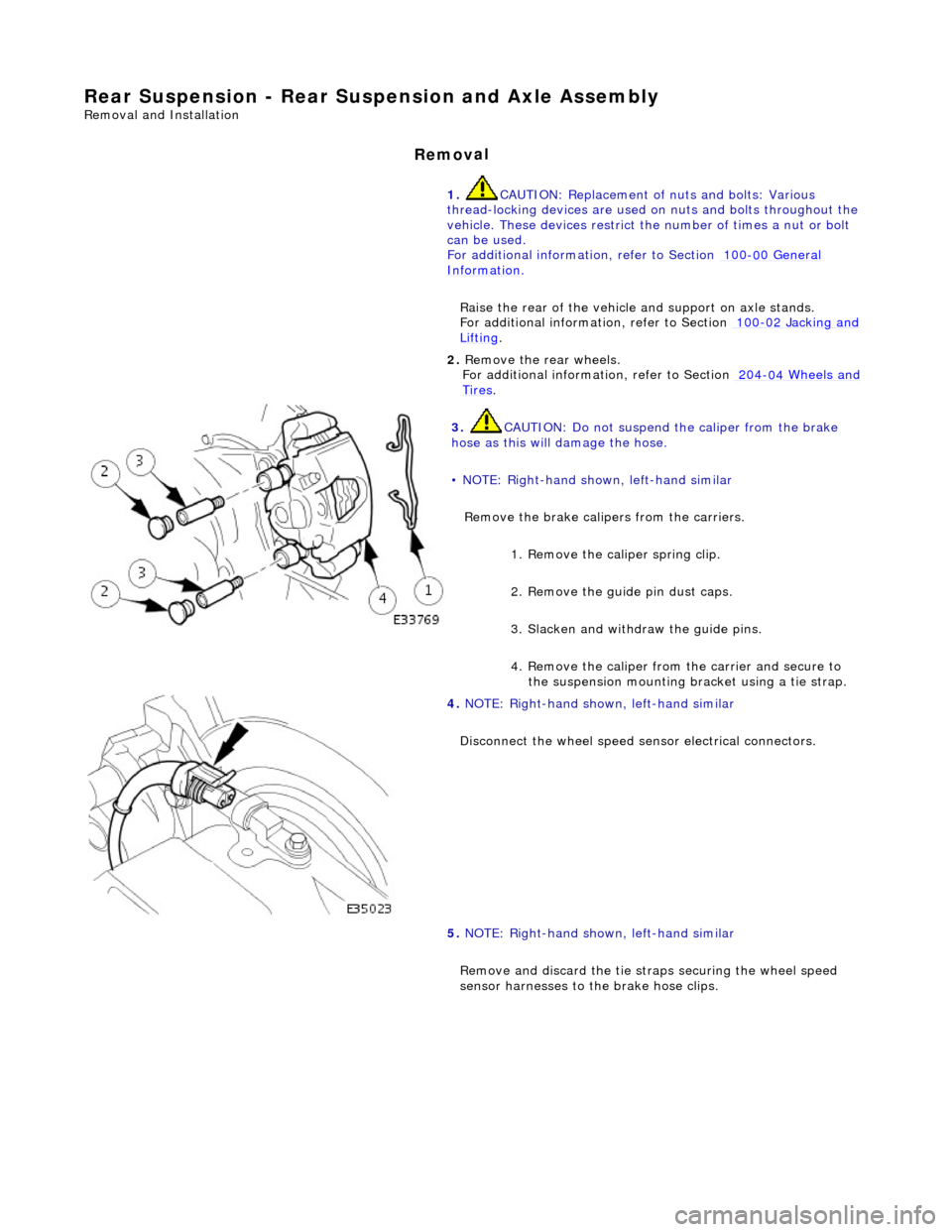
3. CAUTI
ON: Do not suspend the caliper from the brake
hose as this will damage the hose.
• NOTE: Right-hand shown, left-hand similar
Remove the brake calipers from the carriers.
1. Remove the caliper spring clip.
2. Remove the guide pin dust caps.
3. Slacken and withdr aw the guide pins.
4. Remove the caliper from the carrier and secure to the suspension mounting bracket using a tie strap.
4. NOTE
: Right-hand shown, left-hand similar
Disconnect the wheel speed sensor electrical connectors.
5. NOTE: Right-hand shown, left-hand similar
Remove and discard th e tie straps securing the wheel speed
sensor harnesses to the brake hose clips.