vvt JAGUAR X308 1998 2.G Workshop Manual
[x] Cancel search | Manufacturer: JAGUAR, Model Year: 1998, Model line: X308, Model: JAGUAR X308 1998 2.GPages: 2490, PDF Size: 69.81 MB
Page 9 of 2490

303‐01: En gine
Diagnos
is
and Testing
Engine
DTC P1392 VVT solenoid A circuit low input
DTC P1397 VVT solenoid B circuit low input
DTC P1393 VVT solenoid A circuit high input
DTC P1398 VVT solenoid B circuit high input
DTC P1396 VVT solenoid B malfunction
Pinpoint test A: P13
92 (P1397) VVT solenoid circuit low input
Pinpoint test B: P1393 (P1398) VVT solenoid circuit high input
Pinpoint test C: P1396 VVT solenoid malfunction
In
‐Vehicle Repair
Connecting
Rod Bearings (12.17.16)
Crankshaft
Front Seal Vehicles Without: Supe
rcharger (12.21.14)
Crankshaft
Front Seal Vehicles With: Supercharger (12.21.14)
Crankshaft
Inner Sprocket 4.0L, Vehicles Without: Supercharger (12.65.76)
Crankshaft
Inner Sprocket 3.2L (12.65.76)
Crankshaft
Outer Sprocket (12.65.75)
Crankshaft
Pulley Vehicles Without: Supercharger (12.21.09)
Crankshaft
Pulley Vehicles With: Supercharger (12.21.09)
Crankshaft
Rear Seal Vehicles Without: Supercharger (12.21.20)
Crankshaft
Rear Seal Vehic
les With: Supercharger (12.21.20)
Cylinder
Head LH (12.29.02)
Cylinder
Head RH (12.29.03)
Engine
Front Cover (12.65.01)
Engine
Front Cover Gasket (12.65.04)
Exhaust
Camshaft LH (12.13.17)
Exhaust
Camshaft RH (12.13.15)
Exhaust
Camshaft Sprocket LH 4.0L, Vehicles Without: Supercharger (12.65.74)
Exhaust
Camshaft Sprocket LH 3.2L/4.0L, Vehicles With: Supercharger (12.65.74)
Exhaust
Camshaft Sprocket RH 4.0L, Ve
hicles Without: Supercharger (12.65.73)
Exhaust
Camshaft Sprocket RH 3.2L/4.0L, Vehicles With: Supercharger (12.65.73)
Exhaust
Manifold LH (30.15.55)
Exhaust Manifold RH (30.15.56)
Exhaust Manifold LH and RH (30.15.57)
Exhaust Manifold Gasket LH (30.15.58)
Exhaust Manifold Gasket RH (30.15.59)
Exhaust Manifold Gasket LH and RH (30.15.60)
Page 48 of 2490
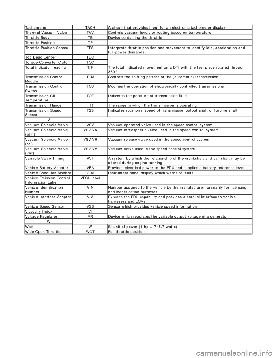
Tacho
meter
TACHA
ci
rcuit that provides input for
an electronic tachometer display
Thermal Vacuu
m Valve
TVVControls vacuum l
e
vels or
routing based on temperature
Throttle
Body
TBDe
vi
ce containing the throttle
Throttl
e
Position
TP
Throttl
e
Position Sensor
TPSInterprets throttl
e
position and movement to iden tify idle, acceleration and
full-power demands
Top Dead CenterTDC
Torque Converter C
lutch
TCC
To
tal
indicator reading
TIRThe t
o
tal indicated movement on a DTI with the test piece rotated through
360°
Transm
ission Control
Module
TCMControls
the shifting pattern
of the (automatic) transmission
Transm
ission Control
Switch
TCSModifi es
the operation of electronically controlled transmissions
Transmission Oil
TemperatureTOTIndi
cat
es temperature of transmission fluid
Transmission RangeTRThe ran
g
e in which the transmission is operating
Transmission Spe
e
d
Sensor
TSSIndi cat
es rotational speed of transmission output shaft or turbine shaft
V
Vacuu
m
Solenoid Valve
VSVVacuu
m
operated valve used in the speed control system
Vacuu
m
Solenoid Valve
(atm)
VSV VAVacuu m
atmospheric valve used in the speed control system
Vacuu
m
Solenoid Valve
(rel)
VSV VRVacuu m
release valve used in the speed control system
Vacuu
m
Solenoid Valve
(vac)
VSV VVVacuu m
valve used in the speed control system
Variable Valve TimingVVTA
s
ystem by which the relationship of the crankshaft and camshaft may be
altered during engine running
Vehi cl
e Battery Adapter
VBAProvide
s
electrical power to the PDU
and supplies a battery reference level
Vehicl
e Condition Monitor
VCMInst
rum
ent panel display which warns of faults
Ve
hic
le Emission Control
Information Label
VECI Label
Vehi cl
e Identification
Number
VINN u
mber assigned to the vehicle by the manufacturer, primarily for licensing
and identification purposes
Vehi cl
e Interface Adapter
VIAExtends the
PDU ca
pability and provid
es a parallel interface to vehicle
harnesses and ECMs
Vehicle Spe e
d Sensor
VSSSens
or which provides ve
hicle speed information
Viscosity In
dexVI
Voltage RegulatorVRDe
vice which regulates the variable output voltage of a generator
W
Wat
tWSI unit of power (1 hp = 7
45.7 watts)
W
i
de Open Throttle
WO
TFu
ll throttle position
Page 521 of 2490
Engine System - General Infor
mation - Engine
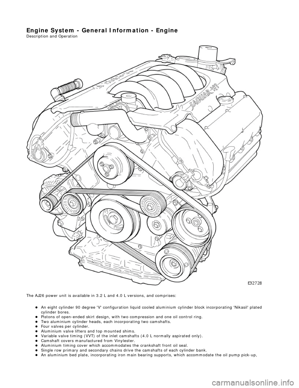
Description an
d Operation
The AJ26 power unit is available in 3.2 L and 4.0 L versions, and comprises:
An eight cylinder 9
0 degree 'V' config
uration liquid cooled aluminium cylinder block incorporating 'Nikasil' plated
cylinder bores.
Pi
stons of open-ended skirt design, with
two compression and one oil control ring.
Two al
uminium cylinder heads, each
incorporating two camshafts.
F
our valves per cylinder.
Al
uminium valve lifters and top mounted shims.
Vari
able valve timing (VVT) of the inlet camshafts (4.0 L normally aspirated only).
Camshaft
covers manufactured from Vinylester.
Al
uminium timing cover which accommodat
es the crankshaft front oil seal.
Sin
gle row primary and secondary chains dr
ive the camshafts of each cylinder bank.
An alu
minium bed pl
ate, incorporating iron main bearing supports, which accomm odate the oil pump pick-up,
Page 531 of 2490
En
gine - Engine
D
iagnosis and Testing
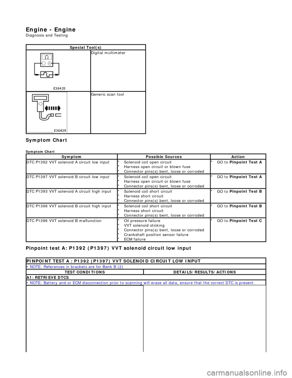
Sym
ptom Chart
Sy
mptom Chart
Pinp
oint test A: P1392 (P1397)
VVT solenoid circuit low input
S
pecial Tool(s)
D
igital multimeter
Generi
c scan tool
Sy
mptom
Possib
le Sources
Acti
on
D
TC P1392 VVT solenoid A circuit low input
So
lenoid coil open circuit
Harness open circuit or blown fuse
Connector pins(s) bent , loose or corroded
*
*
*
GO to
P
inpoint Test A
*
D
TC P1397 VVT solenoid B circuit low input
So
lenoid coil open circuit
Harness open circuit or blown fuse
Connector pins(s) bent , loose or corroded
*
*
*
GO to
P
inpoint Test A
*
D
TC P1393 VVT solenoid A circuit high input
So
lenoid coil short circuit
Harness short circuit
Connector pins(s) bent , loose or corroded
*
*
*
GO to
P
inpoint Test B
*
D
TC P1398 VVT solenoid B circuit high input
So
lenoid coil short circuit
Harness short circuit
Connector pins(s) bent , loose or corroded
*
*
*
GO to
P
inpoint Test B
*
D
TC P1396 VVT solenoid B malfunction
O
il pressure failure
VVT solenoid sticking
Connector pins(s) bent , loose or corroded
Crankshaft position sensor failure
ECM failure
*
*
*
*
*
GO to
P
inpoint Test C
*
P
INPOINT TEST A : P1392 (P1397) VVT SOLENOID CIRCUIT LOW INPUT
•
NOTE: References in brac
kets are for Bank B (2)
T
EST CONDITIONS
D
ETAILS/RESULTS/ACTIONS
A1
: RETRIEVE DTCS
•
NOTE: Battery and or ECM disconnection prior to scanning wi
ll erase all data, ensure that the correct DTC is present.
Page 532 of 2490
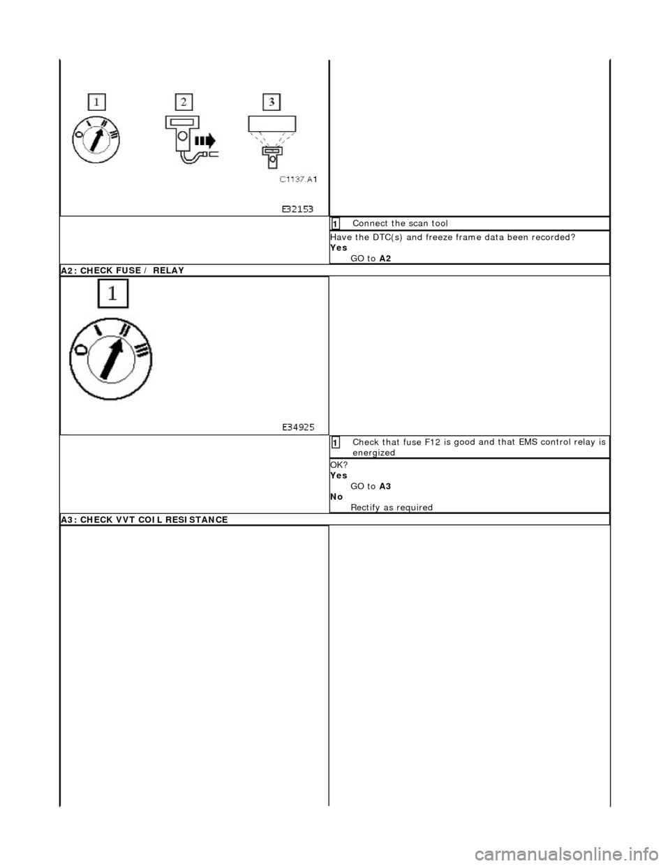
Connect
the scan tool
1
Have the DTC(s) and fr
eeze f
rame data been recorded?
Yes GO to A2
A2: CH
ECK FUSE / RELAY
Check that fuse F
12 i
s good
and that EMS control relay is
energized
1
OK ?
Yes GO to A3
No Rectify as required
A3: CH
ECK VVT COIL RESISTANCE
Page 533 of 2490
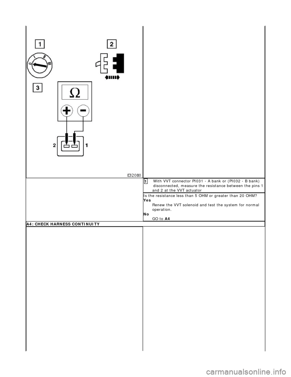
W
ith VVT connector PI031 - A bank or (PI032 - B bank)
disconnected, measure the resistance between the pins 1
and 2 at the VVT actuator
1
I
s the resistance less than 5
OHM or greater than 20 OHM?
Yes Renew the VVT solenoid and te st the system for normal
operation.
No GO to A4
A4: CHECK
HARNESS CONTINUITY
Page 535 of 2490
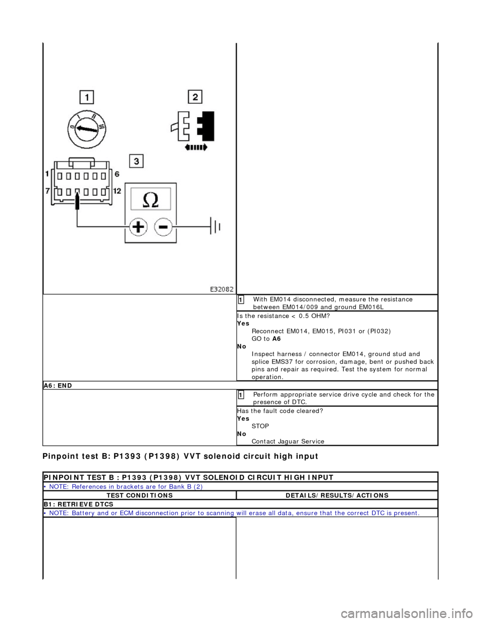
Pin
point test B: P1393 (P1398) VVT solenoid circuit high input
W
ith EM014 disconnected, measure the resistance
between EM014/009 and ground EM016L
1
I
s the resistance < 0.5 OHM?
Yes Reconnect EM014, EM015, PI031 or (PI032)
GO to A6
No Inspect harness / connector EM014, ground stud and
splice EMS37 for corrosion, damage, bent or pushed back
pins and repair as required. Test the system for normal
operation.
A6
: END
Perform
appropriate service drive cycle and check for the
presence of DTC.
1
Has
the fault code cleared?
Yes STOP
No Contact Jaguar Service
P
INPOINT TEST B : P1393 (P1398) VVT SOLENOID CIRCUIT HIGH INPUT
•
NOTE: References in brac
kets are for Bank B (2)
T
EST CONDITIONS
D
ETAILS/RESULTS/ACTIONS
B1
: RETRIEVE DTCS
•
NOTE: Battery and or ECM disconnection prior to scanning wi
ll erase all data, ensure that the correct DTC is present.
Page 536 of 2490
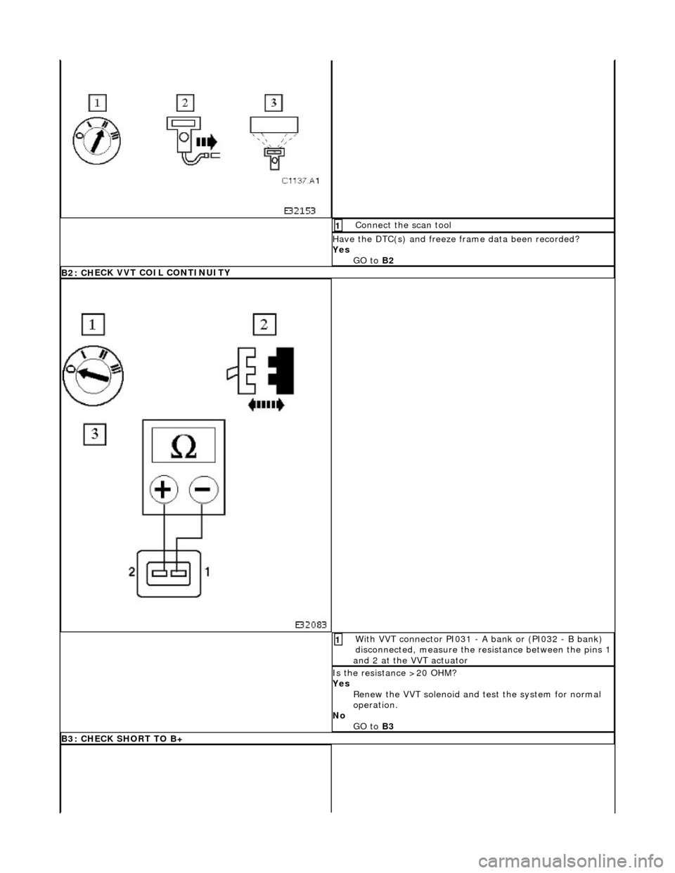
Connect
the scan tool
1
Have the DTC(s) and fr
eeze f
rame data been recorded?
Yes GO to B2
B2 : CH
ECK VVT COIL CONTINUITY
W
i
th VVT connector PI031 - A bank or (PI032 - B bank)
disconnected, measure the resistance between the pins 1
and 2 at the VVT actuator
1
I s
the resistance >20 OHM?
Yes Renew the VVT solenoid and te st the system for normal
operation.
No GO to B3
B3: CHECK
SHORT TO B+
Page 537 of 2490
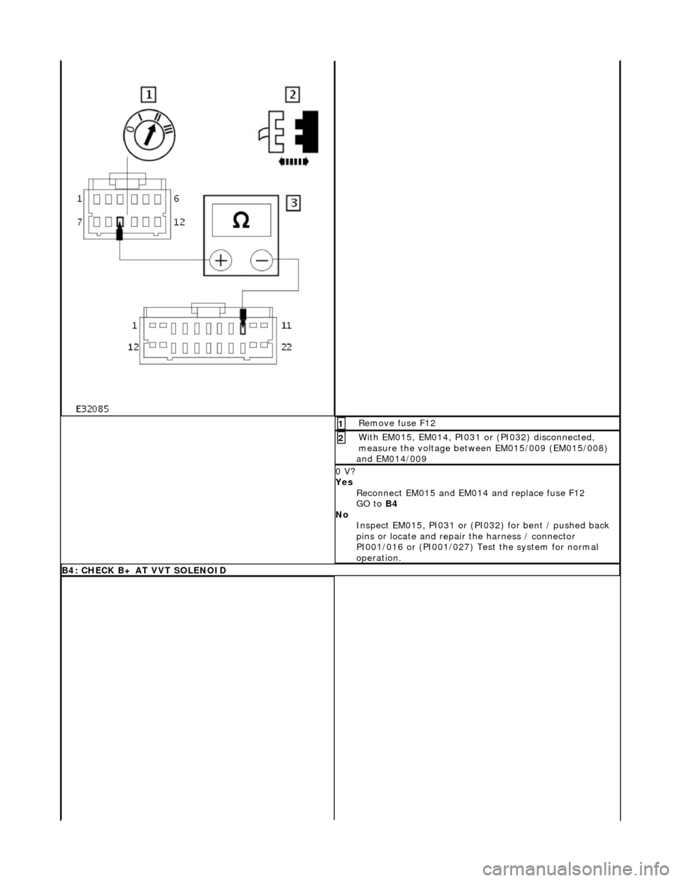
R
emove fuse F12
1
W
ith EM015, EM014, PI031 or (PI032) disconnected,
measure the voltage between EM015/009 (EM015/008)
and EM014/009
2
0 V?
Yes Reconnect EM015 and EM0 14 and replace fuse F12
GO to B4
No Inspect EM015, PI031 or (PI032) for bent / pushed back
pins or locate and repair the harness / connector
PI001/016 or (PI001/027) Test the system for normal
operation.
B4
: CHECK B+ AT VVT SOLENOID
Page 540 of 2490
Pinpoint test C: P1396
VVT solenoid malfunction
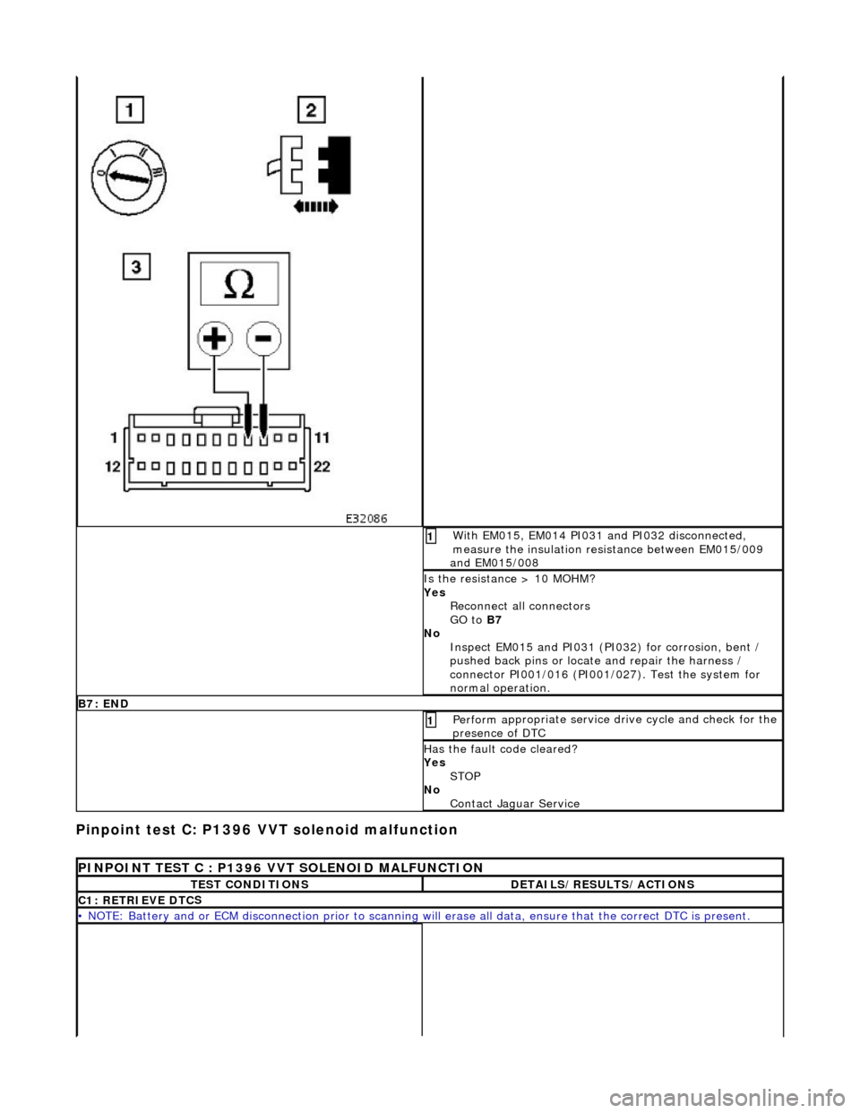
W
i
th EM015, EM014 PI031 and PI032 disconnected,
measure the insulation resistance between EM015/009
and EM015/008
1
I s
the resistance > 10 MOHM?
Yes Reconnect all connectors
GO to B7
No Inspect EM015 and PI031 (PI032) for corrosion, bent /
pushed back pins or locate and repair the harness /
connector PI001/016 (PI001/027). Test the system for
normal operation.
B7: EN
D
Perform
a
ppropriate service drive cycle and check for the
presence of DTC
1
Has th
e fault code cleared?
Yes STOP
No Contact Jaguar Service
PINPOINT TES
T C : P1396 VVT SOLENOID MALFUNCTION
T
E
ST CONDITIONS
D
E
TAILS/RESULTS/ACTIONS
C1
: RETRIEVE DTC
S
•
NOTE
: Battery and or ECM disconnection prior to scanning wi
ll erase all data, ensure that the correct DTC is present.