JAGUAR XF 2009 1.G Owners Manual
Manufacturer: JAGUAR, Model Year: 2009, Model line: XF, Model: JAGUAR XF 2009 1.GPages: 391, PDF Size: 19.32 MB
Page 231 of 391
231
Wheels and tyres
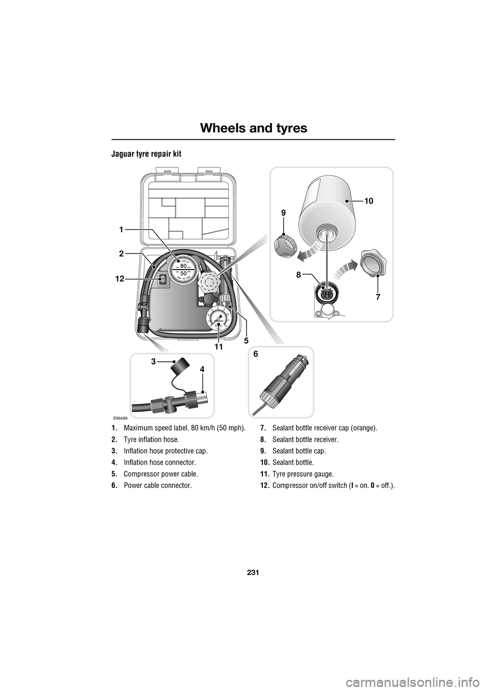
Jaguar tyre repair kit
1.Maximum speed label. 80 km/h (50 mph).
2. Tyre inflation hose.
3. Inflation hose protective cap.
4. Inflation hose connector.
5. Compressor power cable.
6. Power cable connector. 7.
Sealant bottle receiver cap (orange).
8. Sealant bottle receiver.
9. Sealant bottle cap.
10. Sealant bottle.
11. Tyre pressure gauge.
12. Compressor on/off switch ( I = on. 0 = off.).
E96498
34
2
6
5
1
12
11
8
9
10
7
Page 232 of 391
Wheels and tyres
232
Using the Jaguar tyre repair kit
Note: All vehicle drivers and occupants should
be made aware that a temporary repair has
been made to a tyre fitted to the vehicle. They
should also be made aware of the special
driving conditions im posed when using a
repaired tyre.
Repair procedure
1. Open the tyre repair kit and peel off the
maximum speed label. Attach the label to
the fascia in the driver's field of vision.
Take care not to obstruct any of the
instruments or warning lights.
2. Uncoil the compressor power cable and
the inflation hose.
3. Unscrew the orange cap from the sealant
bottle receiver and the sealant bottle cap.
4. Screw the sealant bottle into the receiver
(clockwise) until tight.
•Screwing the bottle onto the receiver will
pierce the bottle's se al. Do not unscrew
a full, or partly us ed bottle from the
receiver. Doing so will result in sealant
leaking from the bottle.
5. Remove the valve cap from the damaged
tyre.
6. Remove the protective cap from the
inflation hose and connect the inflation
hose to the tyre valve. Ensure that the hose
is screwed on firmly.
7. Ensure that the compressor switch is in
the off (0) position.
8. Insert the power cable connector into the
auxiliary power socket. See AUXILIARY
POWER SOCKETS (page 125).
WARNINGS
Avoid skin contact with the sealant
which contains natu ral rubber latex.
If the tyre inflati on pressure does not
reach 1.8 bar (26 lbf/in², 180 kPa)
within seven minutes, the tyre may
have suffered excessive damage. A temporary
repair will not be poss ible, and the vehicle
should not be driven until the tyre has been
replaced.
CAUTIONS
Before attempting a ty re repair, ensure
that the vehicle is parked safely, as far
away from passing traffic as possible.
Ensure that the parki ng brake is applied
and P (Park) is selected.
Do not attempt to remove foreign
objects such as nails, screws, etc. from
the tyre.
Always run the engine when using the
compressor, unless the vehicle is in an
enclosed or poorly ventil ated space, as this
may cause asphyxiation.
To prevent overheating, do not operate
the compressor continuously for longer
than ten minutes.
WARNING
Check the tyre sidewall prior to
inflation. If there are any cracks,
bumps or similar damage, do not
attempt to inflate the tyre. Do not stand
directly beside the tyre while the compressor
is pumping. Watch the ty re sidewall. If any
cracks, bumps or simila r damage appear, turn
off the compressor and let the air out by
means of the pressure relief valve. Do not
continue to use the tyre.
Page 233 of 391
233
Wheels and tyres
9.Unless the vehicle is in an enclosed area,
start the engine.
10. Set the compressor switch to the on ( I)
position.
11. Inflate the tyre to a minimum of 1.9 bar
(26 lbf/in²) and a maximum of 3.5 bar
(51 lbf/in²).
•When pumping the sealant through the
tyre valve, the pressure may rise up to 6
bar (87 lbf/in²). The pressure will drop
again after approximately 30 seconds.
12. During the inflation, switch the
compressor off briefly, to check the tyre
pressure using the gauge mounted on the
compressor.
• It should not take longer than seven
minutes to inflate the tyre. If, after seven
minutes, the tyre has not yet reached
minimum pressure, the tyre should not
be used.
13. Once the tyre has been inflated, switch off
the compressor. If desired, the engine may
be turned off after the compressor has
been turned off.
14. Remove the power connector from the
auxiliary power socket.
15. Remove the inflation hose from the tyre
valve, by unscrewing it as quickly as
possible (count er-clockwise).
16. Replace the inflation hose protective cap
and the tyre valve cap.
17. Do not remove the sealant bottle from the
receiver.
18. Ensure that the tyre repair kit (including
the bottle and receiver caps) are placed
securely in the vehicle. You will need to
use the kit to check the tyre pressure after
approximately 3 km (2 miles), so ensure
they are easily accessible. 19.
Immediately drive the vehicle for
approximately 3 km (2 miles), to allow the
sealant to coat the inner surface of the tyre
and form a seal at the puncture.
Checking the tyre pressure after a repair
1.Drive the vehicle for 3 km (2 miles) then
stop in a safe place. Carry out a visual
examination of the tyres condition.
2. Make sure that the sealant container
section is in its original position.
3. Screw the inflation hos e connector firmly
onto the tyre valve.
4. Read the tyre pressure from the gauge.
5. If the pressure of the sealant filled tyre is
above 1.3 bar (19 lb/in²) adjust the
pressure to the correct value. See TYRE
CARE (page 217).
6. Ensure that the compressor switch is in
the off (O ) position and insert the power
cable connector into the auxiliary power
socket.
If the vehicle is in a well ventilated area,
start the engine.
WARNINGS
When driving the vehicle, if you
experience vibr ations, abnormal
steering, or noises, reduce speed
immediately. Drive with extreme caution and
reduced speed, to the first safe place to stop
the vehicle. Visually examine the tyre and
check its pressure. If there are any signs of
damage or deformity to the tyre, or the tyre
pressure is below 1.3 bar (19 lb/in²), do not
continue driving.
Consult a tyre repair centre or your
Dealer/Authorised Repairer, for
advice concerning the replacement of
a tyre after using a tyre repair kit.
Page 234 of 391
Wheels and tyres
234
7.Switch the compressor to on ( I) and inflate
the tyre to the correct pressure.
8. To check the tyre pressure, turn off the
compressor then read the pressure from
the gauge.
9. When the compressor is off, if the tyre
pressure is too high, release the required
amount of pressure using the pressure
relief valve.
10. Once the tyre is inflated to the correct
pressure, switch off the compressor and
remove the power plug from the auxiliary
socket.
•The use of the tyre re pair kit sealant may
lead to error prompts and incorrect
readings of the Tyre Pressure
Monitoring System. Therefore, use the
tyre repair kit pressure gauge to check
and adjust the damaged tyre's inflation
pressure.
11. Unscrew the inflation hose connector from
the tyre valve, replace the tyre valve cap
and the inflation hose connector protective
cap.
12. Ensure that the tyre repair kit is placed
securely in the vehicle.
13. Drive to the nearest tyre repair centre or
Dealer/Authorised Repairer, for a
replacement tyre to be fitted. Ensure that
you make the repair centre aware that the
tyre repair kit has been used before the tyre
is removed.
14. Both the tyre inflation hose, and the sealant
container should be replaced once a new
tyre has been fitted. Only sealant containers which are
completely empty should be
disposed of with normal household
waste. Sealant containe rs which contain some
sealant, and the tyre in flation hose, should be
disposed of by a tyre specialist or your
Dealer/Authorised Repairer, in compliance with
local waste dispos al regulations.
TYRE PRESSURE MONITORING
SYSTEM
Note: Non-approved accessories may interfere
with the system. If this occurs, TYRE
PRESSURE SYSTEM FAULT is displayed in the
message centre.
WARNINGS
The Tyre Pressure Monitoring (TPM)
system is NOT a substitute for
manually checking ty re pressures.
The TPM system only provides a low pressure
warning and does not re-i nflate your tyres.
Tyre pressures should be checked regularly
using an accurate pressure gauge when cold.
Failure to properly maintain your pressures
could increase the risk of tyre failure, with
consequential loss of vehicle control and
personal injury.
The TPM system can NOT register
damage to a tyre. Regularly check the
condition of your tyre s, especially if
the vehicle is driven off-road.
CAUTION
When inflating tyre s, care should be
taken to avoid bend ing or damaging the
TPM system valves. Always ensure correct
alignment of the inflation head to the valve
stem.
Page 235 of 391
235
Wheels and tyres
Note: Different types of tyre may affect the
performance of the TPM system. Always
replace tyres in accordance with
recommendations. See TYRE
SPECIFICATIONS - ARDUOUS TERRAIN
(page 239).
Your vehicle may be equipped with a TPM
System which monitors pressure in each tyre
(temporary use spare wheels are not fitted with
sensors and are conseque ntly not monitored).
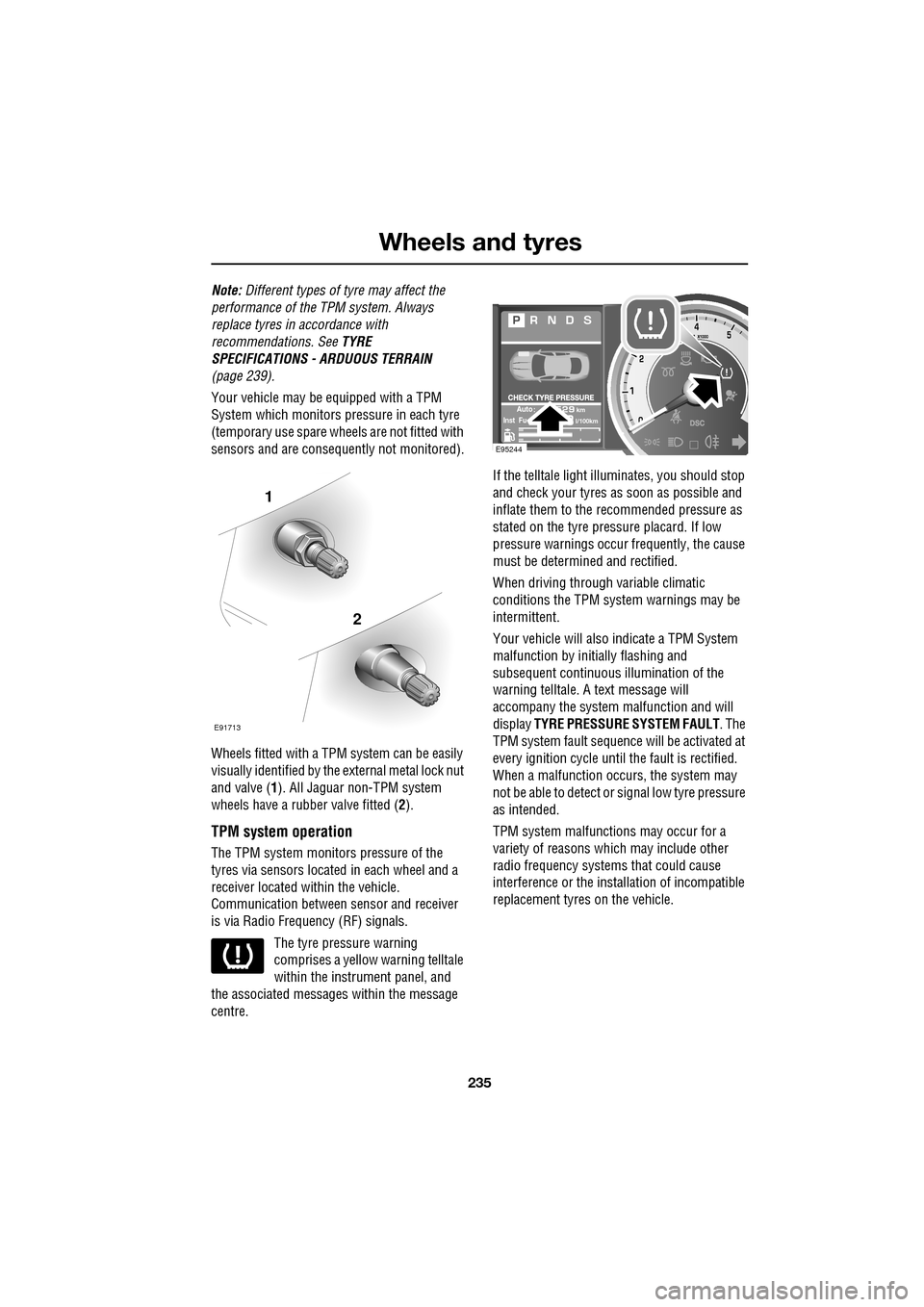
Wheels fitted with a TPM system can be easily
visually identified by the external metal lock nut
and valve ( 1). All Jaguar n on-TPM system
wheels have a rubber valve fitted (2).
TPM system operation
The TPM system monitors pressure of the
tyres via sensors located in each wheel and a
receiver located within the vehicle.
Communication between se nsor and receiver
is via Radio Frequency (RF) signals.
The tyre pressure warning
comprises a yellow warning telltale
within the instrument panel, and
the associated messages within the message
centre. If the telltale light illu
minates, you should stop
and check your tyres as soon as possible and
inflate them to the recommended pressure as
stated on the tyre pressure placard. If low
pressure warnings occur frequently, the cause
must be determined and rectified.
When driving through variable climatic
conditions the TPM syst em warnings may be
intermittent.
Your vehicle will also indicate a TPM System
malfunction by initially flashing and
subsequent continuous illumination of the
warning telltale. A text message will
accompany the system malfunction and will
display TYRE PRESSURE SYSTEM FAULT . The
TPM system fault sequence will be activated at
every ignition cycle until the fault is rectified.
When a malfunction occurs, the system may
not be able to de tect or signal low tyre pressure
as intended.
TPM system malfuncti ons may occur for a
variety of reasons which may include other
radio frequency systems that could cause
interference or the installation of incompatible
replacement tyres on the vehicle.
1
2
E91713
AutokmInst Ful/100km
E95244
Page 236 of 391
Wheels and tyres
236
Tyre pressure warning with speed
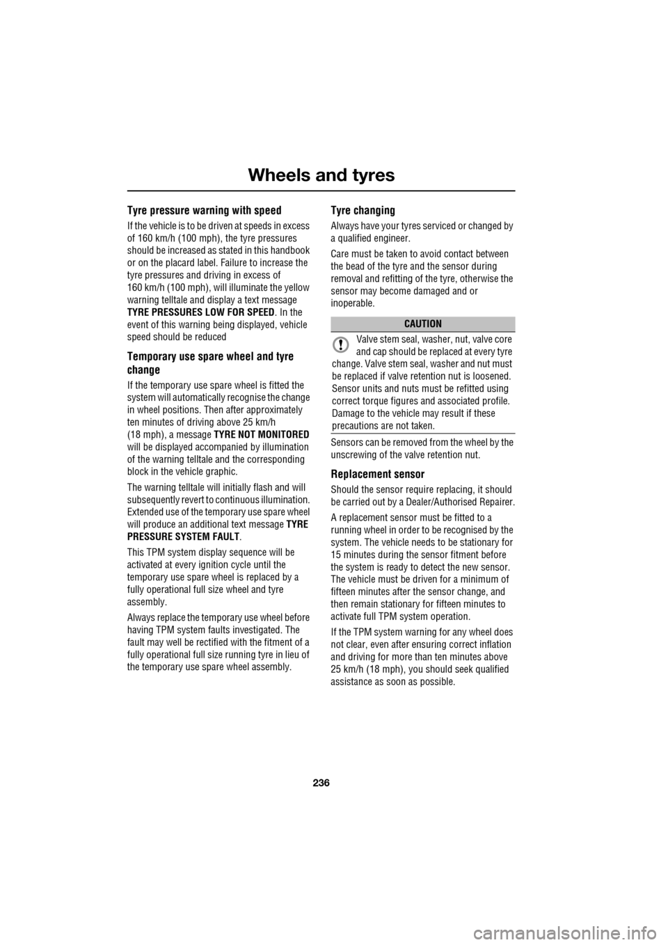
If the vehicle is to be driven at speeds in excess
of 160 km/h (100 mph), the tyre pressures
should be increased as stated in this handbook
or on the placard label. Failure to increase the
tyre pressures and driving in excess of
160 km/h (100 mph), will illuminate the yellow
warning telltale and display a text message
TYRE PRESSURES LOW FOR SPEED . In the
event of this warning be ing displayed, vehicle
speed should be reduced
Temporary use spare wheel and tyre
change
If the temporary use spare wheel is fitted the
system will automatically recognise the change
in wheel positions. The n after approximately
ten minutes of driv ing above 25 km/h
(18 mph), a message TYRE NOT MONITORED
will be displayed accompanied by illumination
of the warning telltale and the corresponding
block in the vehicle graphic.
The warning telltale will initially flash and will
subsequently revert to continuous illumination.
Extended use of the temporary use spare wheel
will produce an additional text message TYRE
PRESSURE SYSTEM FAULT .
This TPM system display sequence will be
activated at every ignition cycle until the
temporary use spare wheel is replaced by a
fully operational full size wheel and tyre
assembly.
Always replace the temporary use wheel before
having TPM system faults investigated. The
fault may well be rectified with the fitment of a
fully operational full size running tyre in lieu of
the temporary use spare wheel assembly.
Tyre changing
Always have your tyres serviced or changed by
a qualified engineer.
Care must be taken to avoid contact between
the bead of the tyre and the sensor during
removal and refitting of the tyre, otherwise the
sensor may become damaged and or
inoperable.
Sensors can be removed from the wheel by the
unscrewing of the va lve retention nut.
Replacement sensor
Should the sensor require replacing, it should
be carried out by a Dealer/Authorised Repairer.
A replacement sensor must be fitted to a
running wheel in order to be recognised by the
system. The vehicle needs to be stationary for
15 minutes during the se nsor fitment before
the system is ready to detect the new sensor.
The vehicle must be driven for a minimum of
fifteen minutes after the sensor change, and
then remain stationary for fifteen minutes to
activate full TPM system operation.
If the TPM system warning for any wheel does
not clear, even after ensuring correct inflation
and driving for more than ten minutes above
25 km/h (18 mph), you should seek qualified
assistance as soon as possible.
CAUTION
Valve stem seal, washer, nut, valve core
and cap should be replaced at every tyre
change. Valve stem seal, washer and nut must
be replaced if valve re tention nut is loosened.
Sensor units and nuts must be refitted using
correct torque figures and associated profile.
Damage to the vehicle may result if these
precautions are not taken.
Page 237 of 391
237
Wheels and tyres
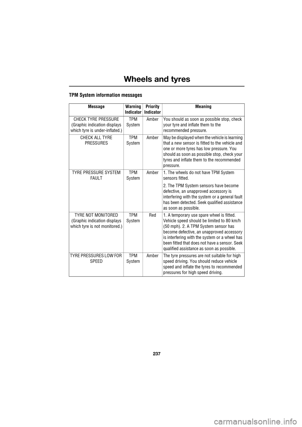
TPM System information messages
Message Warning IndicatorPriority
Indicator Meaning
CHECK TYRE PRESSURE
(Graphic indication displays
which tyre is under-inflated.) TPM
System Amber You should as soon as
possible stop, check
your tyre and inflate them to the
recommended pressure.
CHECK ALL TYRE PRESSURES TPM
System Amber May be displayed when
the vehicle is learning
that a new sensor is fitted to the vehicle and
one or more tyres has low pressure. You
should as soon as possi ble stop, check your
tyres and inflate them to the recommended
pressure.
TYRE PRESSURE SYSTEM FAULT TPM
System Amber 1. The wheels do
not have TPM System
sensors fitted.
2. The TPM System se nsors have become
defective, an unapproved accessory is
interfering with the syst em or a general fault
has been detected. Seek qualified assistance
as soon as possible.
TYRE NOT MONITORED
(Graphic indication displays
which tyre is not monitored.) TPM
System Red 1. A temporary use spare wheel is fitted.
Vehicle speed should be limited to 80 km/h
(50 mph). 2. A TPM System sensor has
become defective, an unapproved accessory
is interfering with the system or a wheel has
been fitted that does not have a sensor. Seek
qualified assistance as soon as possible.
TYRE PRESSURES LOW FOR SPEED TPM
System Amber The tyre pressures ar
e not suitable for high
speed driving. You should reduce vehicle
speed and inflate the tyres to recommended
pressures for high speed driving.
Page 238 of 391
Wheels and tyres
238
TYRE GLOSSARY
lbf/in² or psi
Pounds per square inch, an imperial unit of
measure for pressure.
kPa
Kilo Pascal, a metric unit of measure for
pressure.
Cold tyre pressure
The air pressure in a tyre which has been
standing in excess of th ree hours, or driven for
less than 1.6 km (1 mile).
Maximum inflation pressure
The maximum pressure to which the tyre
should be inflated. This pressure is given on
the tyre side wall in lbf/in² (psi) and kPa.
Note: This pressure is the maximum allowed
by the tyre manufacturer. It is not the pressure
recommended for use.
Kerb weight
The weight of a standa rd vehicle, including a
full tank of fuel, any optional equipment fitted,
and with the correct coolant and oil levels.
Gross vehicle weight
The maximum permissible weight of a vehicle
with driver, passen gers, load, luggage,
equipment, and towbar load.
Accessory weight
The combined weight (in excess of those items
replaced) of items available as factory installed
equipment.
Production options weight
The combined weight of options installed
which weigh in excess of 1.4 kg (3 lb) more
than the standard items that they replaced, and
are not already considered in kerb or accessory
weights. Items such as heavy duty brakes, high
capacity battery, special trim etc.
Vehicle capacity weight
The number of seats multiplied by 68 kg
(150 lb) plus the rated amount of load/luggage.
Maximum loaded vehicle weight
The sum of kerb wei ght, accessory weight,
vehicle capacity weig ht, plus any production
option weights.
Rim
The metal support for a ty re, or tyre and tube,
upon which the tyre beads are seated.
Bead
The inner edge of a tyre th at is shaped to fit to
the rim and form an air tight seal. The bead is
constructed of steel wires which are wrapped,
or reinforced, by the ply cords.
Page 239 of 391
239
Wheels and tyres
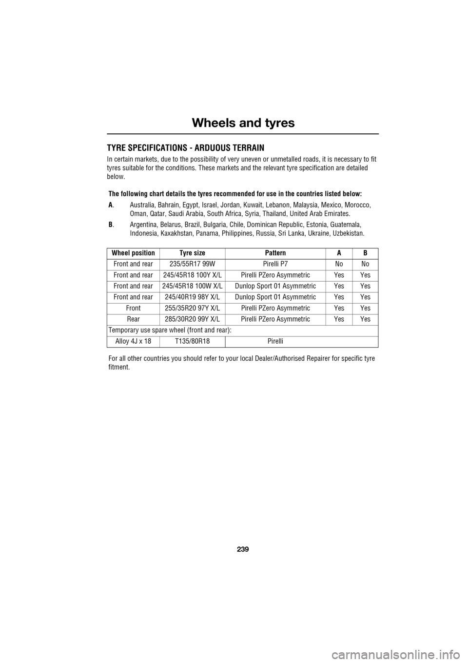
TYRE SPECIFICATIONS - ARDUOUS TERRAIN
In certain markets, due to the possibility of very uneven or unmetalled roads, it is necessary to fit
tyres suitable for the conditions. These markets and the relevant tyre specification are detailed
below.
The following chart details the tyres recomm ended for use in the countries listed below:
A . Australia, Bahrain, Egypt, Is rael, Jordan, Kuwait, Lebanon, Malaysia, Mexico, Morocco,
Oman, Qatar, Saudi Arabia, South Africa, Syria, Thailand, United Arab Emirates.
B . Argentina, Belarus, Brazil, Bulgaria, Chile, Dominican Republic, Estonia, Guatemala,
Indonesia, Kaxakhstan, Panama, Philippines, Russia, Sri Lanka, Ukraine, Uzbekistan.
Wheel position Tyre size PatternA B
Front and rear 235/55R17 99W Pirelli P7No No
Front and rear 245/45R18 100Y X/L Pir elli PZero Asymmetric Yes Yes
Front and rear 245/45R18 100W X/ L Dunlop Sport 01 Asymmetric Yes Yes
Front and rear 245/40R19 98Y X/L D unlop Sport 01 Asymmetric Yes Yes
Front 255/35R20 97Y X/L Pirelli PZero Asymmetric Yes Yes Rear 285/30R20 99Y X/L Pirelli PZero Asymmetric Yes Yes
Temporary use spare wheel (front and rear):
Alloy 4J x 18 T135/80R18 Pirelli
For all other countries you should refer to your local Dealer/Aut horised Repairer for specific tyre
fitment.
Page 240 of 391
Wheels and tyres
240
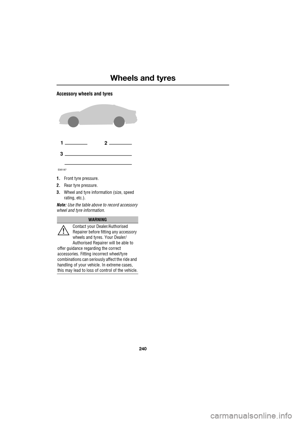
Accessory wheels and tyres
1.Front tyre pressure.
2. Rear tyre pressure.
3. Wheel and tyre information (size, speed
rating, etc.).
Note: Use the table above to record accessory
wheel and tyre information.
WARNING
Contact your Dealer/Authorised
Repairer before fitting any accessory
wheels and tyres. Your Dealer/
Authorised Repairer will be able to
offer guidance rega rding the correct
accessories. Fitting incorrect wheel/tyre
combinations can seriously affect the ride and
handling of your vehicl e. In extreme cases,
this may lead to loss of control of the vehicle.
12
3
E95187