JAGUAR XF 2009 1.G Owners Manual
Manufacturer: JAGUAR, Model Year: 2009, Model line: XF, Model: JAGUAR XF 2009 1.GPages: 391, PDF Size: 19.32 MB
Page 251 of 391
251
Status after a collision
DRIVING AFTER A COLLISION
Before starting or driving
If the vehicle has been involved in an accident
it should be checked thoroughly before
attempting to start the engine or drive the
vehicle.
Check for:-
• Fuel leaks.
• Fluid leaks.
• Battery damage.
• Damage to wiring.
• Damage to lights.
• Damage to steering, suspension, wheels
or tyres.
• Sharp or protruding bodywork.
• Operation of doors and locks.
• Condition and operation of seat belts and
SRS components.
• Activation of the pe destrian protection
system.
• Condition of chil d seats and their
mounting/attach ment points.
Note: This list is not exhaustive.
Resetting the fuel cut-off
The fuel system cut-off forms part of the Safety
and Restraint System (SRS) fitted to your
vehicle. Following an impact, and depending on
the severity, the fuel pump may be switched
off.
1.Switch the ignition off, and wait for 10
seconds.
2. Without pressing the brake pedal, press
the engine START/STOP button, to switch
the electrical circuits on. Wait for 30
seconds.
3. Check the vehicle thoroughly for fuel leaks.
If a leak is detected switch the ignition off
immediately.
•The vehicle must not be started if a leak
is present. Seek qualified advice, and
have the vehicle recovered.
4. If no leaks are detected, start the engine.
WARNING
If the vehicle is involved in a collision
it should be checked by a Dealer/
Authorised repairer, or suitably
qualified personnel, before starting or driving.
WARNING
The fuel cut-off should never be reset
if you can smell fuel, or a leak can be
seen. Doing so can lead to a fire
which may cause personal injury or death.
Page 252 of 391
Status after a collision
252
When driving
When driving a vehicle which has been
involved in a collision use caution and pay extra
attention to the operation of the vehicle. If any
changes in vehicle operation after the collision
are noted when compared to it's operation
before the collision, do not continue to drive
the vehicle. Stop the vehi cle as soon as it is
safe to do so, and have the vehicle recovered.
Pay particular attent ion to changes in:-
• Steering.
• Braking.
• Unusual noises.
• Warning lights or messages displayed.
• Problems with electrical systems.
INSPECTING SAFETY SYSTEM
COMPONENTS
Following a collision the seat belt and
Supplementary Restrain t System components
should be inspected for damage and/or
deformity. The inspection and any subsequent
repair work should only be carried out by a
Dealer/Authorised Repair er, or other suitably
qualified personnel.
Components which require inspection
include:-
• Seat belt webbing and mechanisms.
• Seat belt pre-tensioners.
• Airbag covers and modules.
• Seat frames a nd mounting points.
• Child seats.
• Child seat anchor points.
• Pedestrian prot ection system.
Note: This list is not exhaustive.
In addition to the physical items checked, the
electronic control system and its associated
wiring should also be checked thoroughly. This
process will include a diagnostic check which
can only be carried out by a Dealer/Authorised
repairer or suitably qualified and equipped
persons.
WARNING
It is not recommended that the
vehicle be driven or used until all of
the occupant protection systems
have been checked.
Page 253 of 391
253
Vehicle recovery
TOWING POINTS
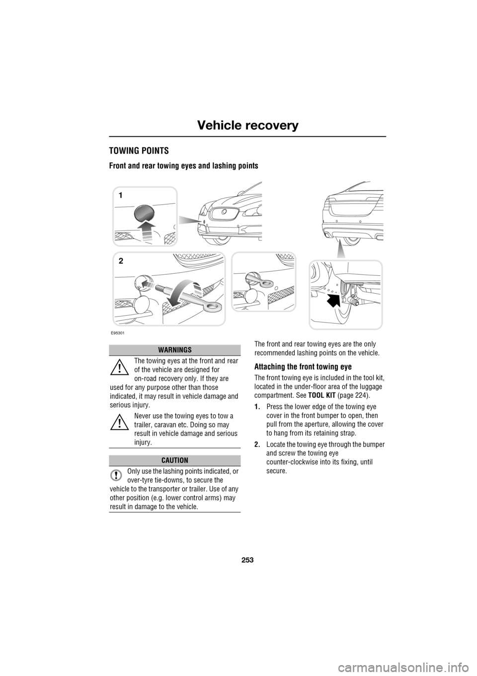
Front and rear towing eyes and lashing points
The front and rear towing eyes are the only
recommended lashing points on the vehicle.
Attaching the front towing eye
The front towing eye is included in the tool kit,
located in the under-floor area of the luggage
compartment. See TOOL KIT (page 224).
1. Press the lower edge of the towing eye
cover in the front bumper to open, then
pull from the aperture, allowing the cover
to hang from its retaining strap.
2. Locate the towing eye through the bumper
and screw the towing eye
counter-clockwise into its fixing, until
secure.
E95301
1
2
WARNINGS
The towing eyes at the front and rear
of the vehicle are designed for
on-road recovery only. If they are
used for any purpose other than those
indicated, it may result in vehicle damage and
serious injury.
Never use the towing eyes to tow a
trailer, caravan etc. Doing so may
result in vehicle damage and serious
injury.
CAUTION
Only use the lashing points indicated, or
over-tyre tie-downs, to secure the
vehicle to the transporter or trailer. Use of any
other position (e.g. lower control arms) may
result in damage to the vehicle.
Page 254 of 391
Vehicle recovery
254
TRANSPORTING THE VEHICLE
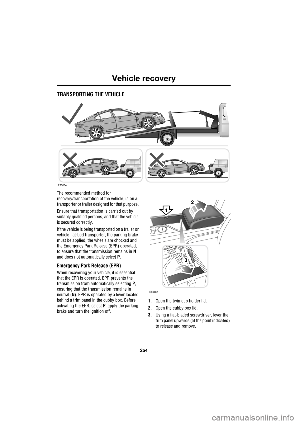
The recommended method for
recovery/transportation of the vehicle, is on a
transporter or trailer de signed for that purpose.
Ensure that transporta tion is carried out by
suitably qualified persons , and that the vehicle
is secured correctly.
If the vehicle is being tr ansported on a trailer or
vehicle flat-bed transporter, the parking brake
must be applied, the wheels are chocked and
the Emergency Park Re lease (EPR) operated,
to ensure that the transmission remains in N
and does not automatically select P.
Emergency Park Release (EPR)
When recovering your vehicle, it is essential
that the EPR is operated. EPR prevents the
transmission from automatically selecting P,
ensuring that the transmission remains in
neutral ( N). EPR is operated by a lever located
behind a trim panel in the cubby box. Before
activating the EPR, select P, apply the parking
brake and turn the ignition off. 1.
Open the twin cup holder lid.
2. Open the cubby box lid.
3. Using a flat-bladed screwdriver, lever the
trim panel upwards (at the point indicated)
to release and remove.
E95304
2
3
E96407
1
Page 255 of 391
255
Vehicle recovery
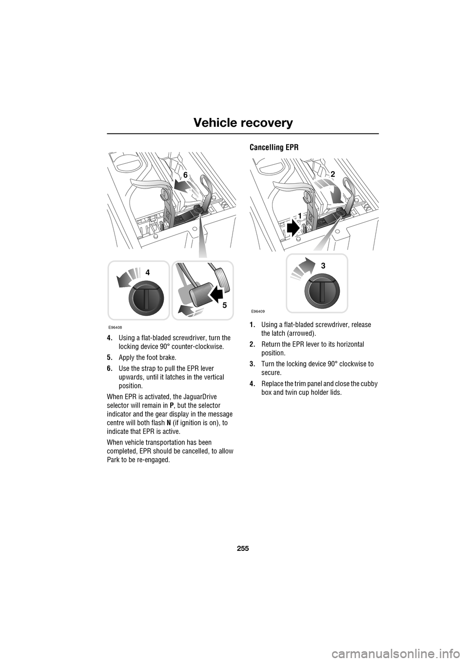
4.Using a flat-bladed screwdriver, turn the
locking device 90° counter-clockwise.
5. Apply the foot brake.
6. Use the strap to pull the EPR lever
upwards, until it latches in the vertical
position.
When EPR is activated, the JaguarDrive
selector will remain in P , but the selector
indicator and the gear display in the message
centre will both flash N (if ignition is on), to
indicate that EPR is active.
When vehicle transportation has been
completed, EPR should be cancelled, to allow
Park to be re-engaged.
Cancelling EPR
1. Using a flat-bladed sc rewdriver, release
the latch (arrowed).
2. Return the EPR lever to its horizontal
position.
3. Turn the locking device 90° clockwise to
secure.
4. Replace the trim pane l and close the cubby
box and twin cup holder lids.E96408
4
5
62
1
E96409
3
Page 256 of 391
Vehicle recovery
256
TOWING THE VEHICLE ON FOUR
WHEELS
Note: The recommended recovery method is
to raise all four wheels.
Towing procedure
1. The vehicle should be parked on firm level
ground, with the parking brake on, and the
gear selector in P (Park).
2. Secure the towing attachment from the
recovery vehicle to the front towing eye.
See TOWING POINTS (page 253).
3. Dock the Jaguar Smart Key and switch on
the ignition. See GENERAL INFORMATION
(page 132). 4.
Apply the foot brake and release the
parking brake.
5. With the foot brake st ill applied, activate
the Emergency Park Release (EPR).
See TRANSPORTING THE VEHICLE
(page 254).
6. The vehicle can now be towed a maximum
of 0.8 km (0.5 miles) at a maximum speed
of 48 kmh (30 mph).
7. Upon arrival at the destination, ensure
wherever possible that the vehicle is
parked on firm level ground.
8. Lower the Emergency Park Release (EPR)
lever, to cancel EP R and to re-engage P
(Park).
9. Apply the parking brake.
10. Switch off the ignition and remove the
Jaguar Smart Key.
11. Remove the towing attachment from the
towing eye.
WARNINGS
Ensure that the remote control
remains docked whilst the vehicle is
being towed. Removing the remote
control will engage the steering lock, which
will prevent the vehicle from steering
correctly.
If the engine cannot be run whilst the
vehicle is being towed, there will be
no power assistance for the steering
or brakes. This will result in greater effort
being required to steer or slow the vehicle, and
greatly increased stopping distances.
CAUTIONS
The vehicle should only be towed in a
forward direction with all four wheels on
the ground.
The vehicle should only be towed for a
maximum of 0.8 km (0.5 miles), at a
maximum speed of 48 km/h (30 mph). Towing
for a greater distance or at a higher speed, may
result in serious damage to the transmission.
CAUTION
Leaving the ignition switched on for
extended periods will cause the battery
to drain.
WARNING
Use extreme caution when detaching
towing equipment. Vehicle movement
is possible which can result in serious
injuries.
Page 257 of 391
257
Vehicle identification
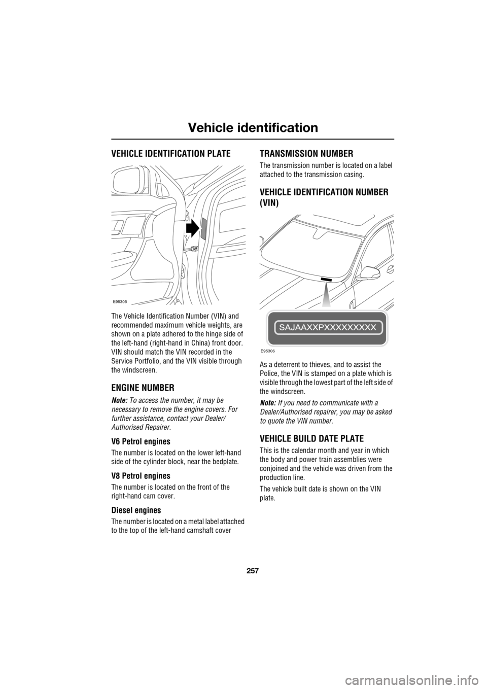
VEHICLE IDENTIFICATION PLATE
The Vehicle Identification Number (VIN) and
recommended maximum vehicle weights, are
shown on a plate adhered to the hinge side of
the left-hand (right-hand in China) front door.
VIN should match the VIN recorded in the
Service Portfolio, and the VIN visible through
the windscreen.
ENGINE NUMBER
Note: To access the number, it may be
necessary to remove the engine covers. For
further assistance, contact your Dealer/
Authorised Repairer.
V6 Petrol engines
The number is located on the lower left-hand
side of the cylinder bloc k, near the bedplate.
V8 Petrol engines
The number is located on the front of the
right-hand cam cover.
Diesel engines
The number is located on a metal label attached
to the top of the left-hand camshaft cover
TRANSMISSION NUMBER
The transmission number is located on a label
attached to the transmission casing.
VEHICLE IDENTIFICATION NUMBER
(VIN)
As a deterrent to thieves, and to assist the
Police, the VIN is stamped on a plate which is
visible through the lowest part of the left side of
the windscreen.
Note: If you need to communicate with a
Dealer/Authorised repairer, you may be asked
to quote the VIN number.
VEHICLE BUILD DATE PLATE
This is the calendar mont h and year in which
the body and power train assemblies were
conjoined and the vehicle was driven from the
production line.
The vehicle built date is shown on the VIN
plate.
E95305
E95306
Page 258 of 391
Technical specifications
258
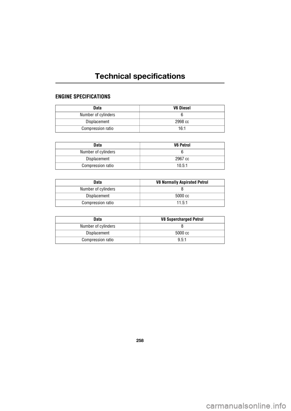
ENGINE SPECIFICATIONS
DataV6 Diesel
Number of cylinders 6
Displacement 2998 cc
Compression ratio 16:1
DataV6 Petrol
Number of cylinders 6
Displacement 2967 cc
Compression ratio 10.5:1
DataV8 Normally Aspirated Petrol
Number of cylinders 8
Displacement 5000 cc
Compression ratio 11.5:1
DataV8 Supercharged Petrol
Number of cylinders 8
Displacement 5000 cc
Compression ratio 9.5:1
Page 259 of 391
259
Technical specifications
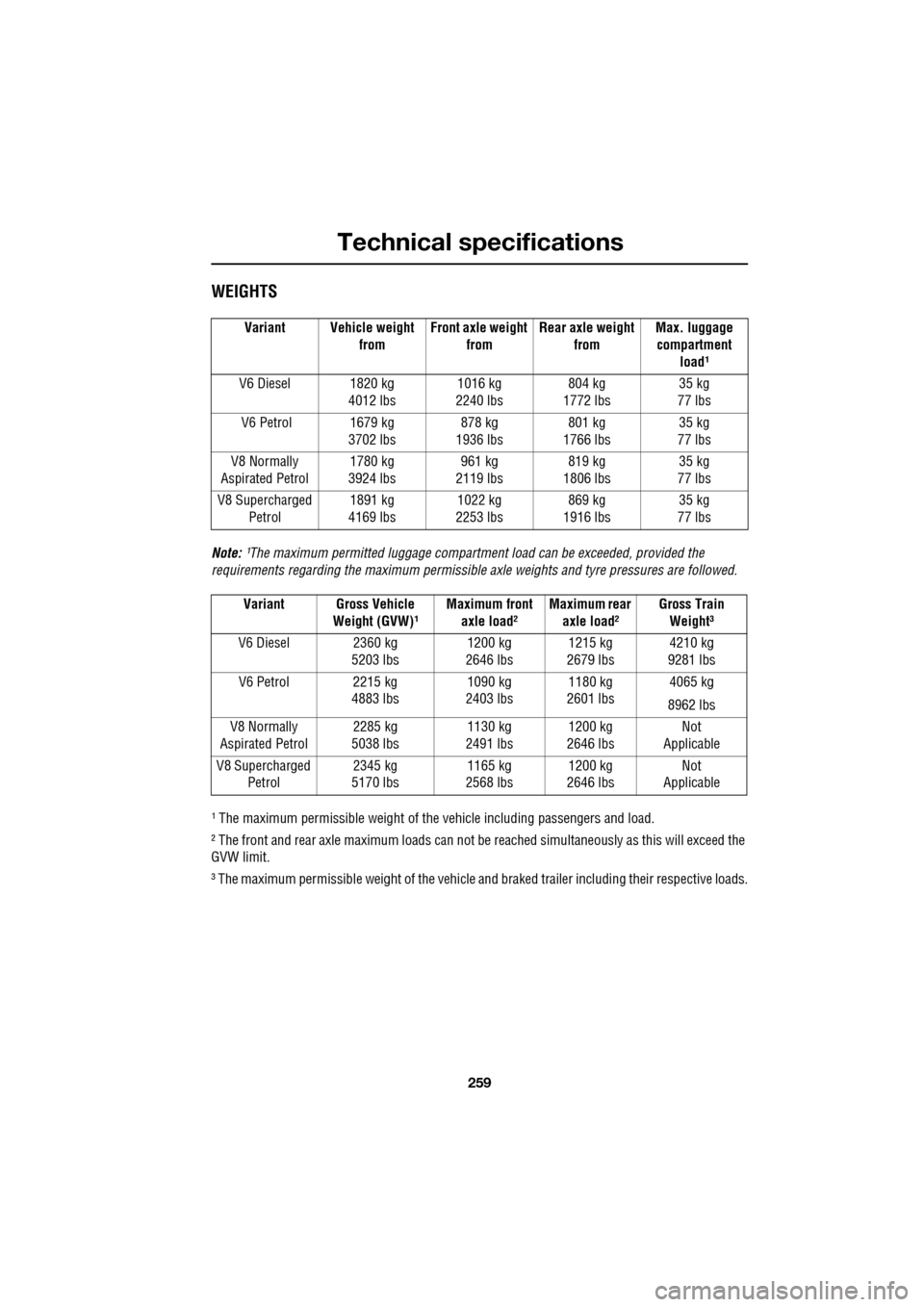
WEIGHTS
Note: ¹The maximum permitted lugga ge compartment load can be exceeded, provided the
requirements regarding the maximu m permissible axle weights and tyre pressures are followed.
¹ The maximum permissible weight of the vehicle incl uding passengers and load.
² The front and rear axle maximum loads can not be reached simultaneously as this will exceed the
GVW limit.
³ The maximum permissible weight of the vehicle and braked trailer including their respective loads.
Variant Vehicle weight
fromFront axle weight
from Rear axle weight
from Max. luggage
compartment load¹
V6 Diesel 1820 kg 4012 lbs1016 kg
2240 lbs 804 kg
1772 lbs 35 kg
77 lbs
V6 Petrol 1679 kg 3702 lbs 878 kg
1936 lbs 801 kg
1766 lbs 35 kg
77 lbs
V8 Normally
Aspirated Petrol 1780 kg
3924 lbs 961 kg
2119 lbs 819 kg
1806 lbs 35 kg
77 lbs
V8 Supercharged Petrol 1891 kg
4169 lbs 1022 kg
2253 lbs 869 kg
1916 lbs 35 kg
77 lbs
Variant Gross Vehicle
Weight (GVW)¹ Maximum front
axle load² Maximum rear
axle load² Gross Train
Weight³
V6 Diesel 2360 kg 5203 lbs 1200 kg
2646 lbs 1215 kg
2679 lbs 4210 kg
9281 lbs
V6 Petrol 2215 kg 4883 lbs 1090 kg
2403 lbs 1180 kg
2601 lbs 4065 kg
8962 lbs
V8 Normally
Aspirated Petrol 2285 kg
5038 lbs 1130 kg
2491 lbs 1200 kg
2646 lbs Not
Applicable
V8 Supercharged Petrol 2345 kg
5170 lbs 1165 kg
2568 lbs 1200 kg
2646 lbs Not
Applicable
Page 260 of 391
Technical specifications
260
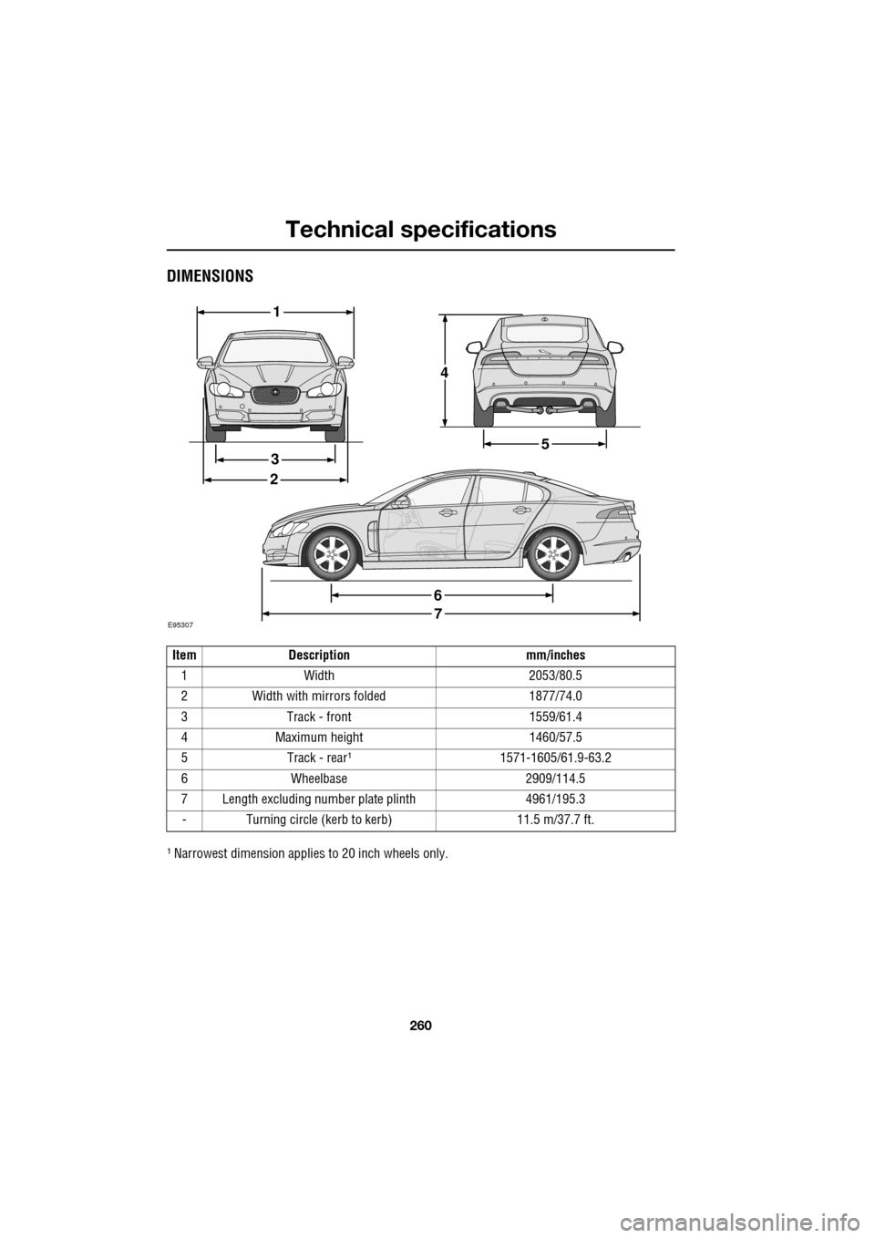
DIMENSIONS
¹ Narrowest dimension applies to 20 inch wheels only.
E95307
1
2
3
4
5
6
7
Item Description mm/inches
1 Width 2053/80.5
2 Width with mirrors folded 1877/74.0
3 Track - front 1559/61.4
4 Maximum height 1460/57.5
5 Track - rear¹ 1571-1605/61.9-63.2
6 Wheelbase 2909/114.5
7 Length excluding numbe r plate plinth 4961/195.3
- Turning circle (kerb to kerb)11.5 m/37.7 ft.