JAGUAR XFR 2010 1.G Workshop Manual
Manufacturer: JAGUAR, Model Year: 2010, Model line: XFR, Model: JAGUAR XFR 2010 1.GPages: 3039, PDF Size: 58.49 MB
Page 1651 of 3039

DTC Description Possible Causes Action for further assistance P0501-62
Vehicle Speed Sensor A
Range/Performance - Signal
compare failure
Vehicle speed - range
performance
Check ABS/TCM for related DTCs and refer
to relevant DTC Index P0504-00 Brake Switch A / B Correlation
- No sub type information
The brake pressure reading
does not agree with the
brake light switch value
Carry out any pinpoint tests associated with
this DTC using the manufacturer approved
diagnostic system. Refer to the electrical
circuit diagrams and check brake switch
circuits for short, open circuit, high
resistance P0504-01 Brake Switch A / B Correlation
- General electrical failure
Brake switch high fault:
- Brake lights stuck
on
- Gearshift interlock
inoperative
- Speed control
inoperative
Brake switch low fault:
- Brake lights
inoperative
- Gearshift stuck in
Park
- Reduced engine
braking
Carry out any pinpoint tests associated with
this DTC using the manufacturer approved
diagnostic system. Refer to the electrical
circuit diagrams and check brake switch
circuits for short, open circuit, high
resistance P0566-00
Cruise Control OFF Signal - No
sub type information
Speed control Cancel
switch 2 stuck closed
Refer to the electrical circuit diagrams and
check speed control switch circuits for short,
open circuit. Check for stuck switch. Check
and install a new speed control switch as
required P0567-00
Cruise Control DECREASE
DISTANCE Signal - No sub
type information
Speed control Resume
switch 7 stuck closed
Refer to the electrical circuit diagrams and
check speed control switch circuits for short,
open circuit. Check for stuck switch. Check
and install a new speed control switch as
required P0568-00
Cruise Control INCREASE
DISTANCE Signal - No sub
type information
Speed control Accel Set
Plus Switch 6 stuck closed
Check and install a new speed control
switch as required P0569-00
Cruise Control COAST Signal -
No sub type information
Speed control Coast Set
Minus switch 3 stuck
closed
Refer to the electrical circuit diagrams and
check speed control switch circuits for short,
open circuit. Check for stuck switch. Check
and install a new speed control switch as
required P056A-00
Cruise Control INCREASE
DISTANCE Signal - No sub
type information
Speed control Headway
Plus switch 4 stuck closed
Refer to the electrical circuit diagrams and
check speed control switch circuits for short,
open circuit. Check for stuck switch. Check
and install a new speed control switch as
required P056B-00
Cruise Control DECREASE
DISTANCE Signal - No sub
type information
Speed control Headway
Minus switch 5 stuck
closed
Refer to the electrical circuit diagrams and
check speed control switch circuits for short,
open circuit. Check for stuck switch. Check
and install a new speed control switch as
required P0571-62
Brake Switch A Circuit - Signal
compare failure
Plausibility error
Refer to the electrical circuit diagrams and
check brake light switch signal circuits for
short, open circuit. Check and install a new
brake light switch as required P0575-01
Cruise Control Input Circuit -
General electrical failure
General electrical failure
Check speed control system for related
DTCs and refer to relevant DTC Index. Carry
out CAN network integrity tests using the
Page 1652 of 3039

DTC Description Possible Causes Action manufacturer approved diagnostic system P0576-16
Cruise Control Input Circuit
Low - Circuit voltage below
threshold
Circuit voltage below
threshold
Check speed control system for related
DTCs and refer to relevant DTC Index. Carry
out CAN network integrity tests using the
manufacturer approved diagnostic system P0577-17
Cruise Control Input Circuit
High - Circuit voltage above
threshold
Circuit voltage above
threshold
Check speed control system for related
DTCs and refer to relevant DTC Index. Carry
out CAN network integrity tests using the
manufacturer approved diagnostic system P0578-00
Cruise Control Multi-Function
Input A Circuit Stuck - No sub
type information
One of speed control
switches stuck
Check for stuck speed control switch, install
a new switch pack as required P0578-1C
Cruise Control Multi-Function
Input A Circuit Stuck - Circuit
voltage out of range
Circuit voltage out of range
Refer to the electrical circuit diagrams and
check speed control switch circuits for short,
open circuit. Check for stuck switch. Check
and install a new speed control switch as
required P0579-1C
Cruise Control Multi-Function
Input A Circuit
Range/Performance - Circuit voltage out of range
Speed control switch pack
internal failure
Check and install a new speed control
switch pack as required P0579-29
Cruise Control Multi-Function
Input A Circuit
Range/Performance - Signal
invalid
Signal invalid
Refer to the electrical circuit diagrams and
check speed control switch circuits for short,
open circuit. Check for stuck switch. Check
and install a new speed control switch as
required P0590-00
Cruise Control Multi-Function
Input B Circuit Stuck - No sub
type information
Active speed limiter fault
Check for active speed limiter fault, install a
new transmission shift module as required
Page 1653 of 3039
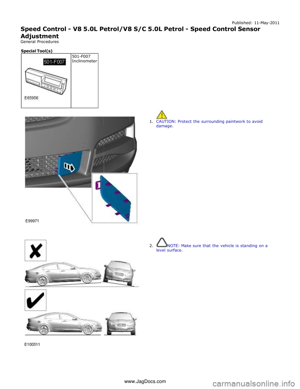
Published: 11-May-2011
Speed Control - V8 5.0L Petrol/V8 S/C 5.0L Petrol - Speed Control Sensor
Adjustment
General Procedures
1. CAUTION: Protect the surrounding paintwork to avoid
damage.
2. NOTE: Make sure that the vehicle is standing on a
level surface. 501-F007
Inclinometer Special Tool(s) www.JagDocs.com
Page 1654 of 3039

3. NOTE: Make sure that the vehicle is standing on a level
surface.
Special Tool(s): 501-F007
4. NOTES:
Do not release the lock nut.
Make sure that the vehicle is standing on a level
surface.
Special Tool(s): 501-F007
5. CAUTION: Protect the surrounding paintwork to avoid
damage.
6.
Configure the ACC module using the diagnostic tool.
This procedure is required if:
A new ACC radar and, or ACC module are installed.
The ACC radar needed to be removed or is misaligned in its
position due to another repair operation.
7.
From the diagnostic tool menu, select: Service Alignment Mode.
Page 1655 of 3039

Page 1656 of 3039

Published: 03-Jan-2013
Speed Control - V8 5.0L Petrol/V8 S/C 5.0L Petrol - Speed Control Deactivator
Switch
Removal and Installation
Removal
1. Refer to: Stoplamp Switch (417-01, Removal and Installation).
Installation
1. Refer to: Stoplamp Switch (417-01, Removal and Installation).
Page 1657 of 3039
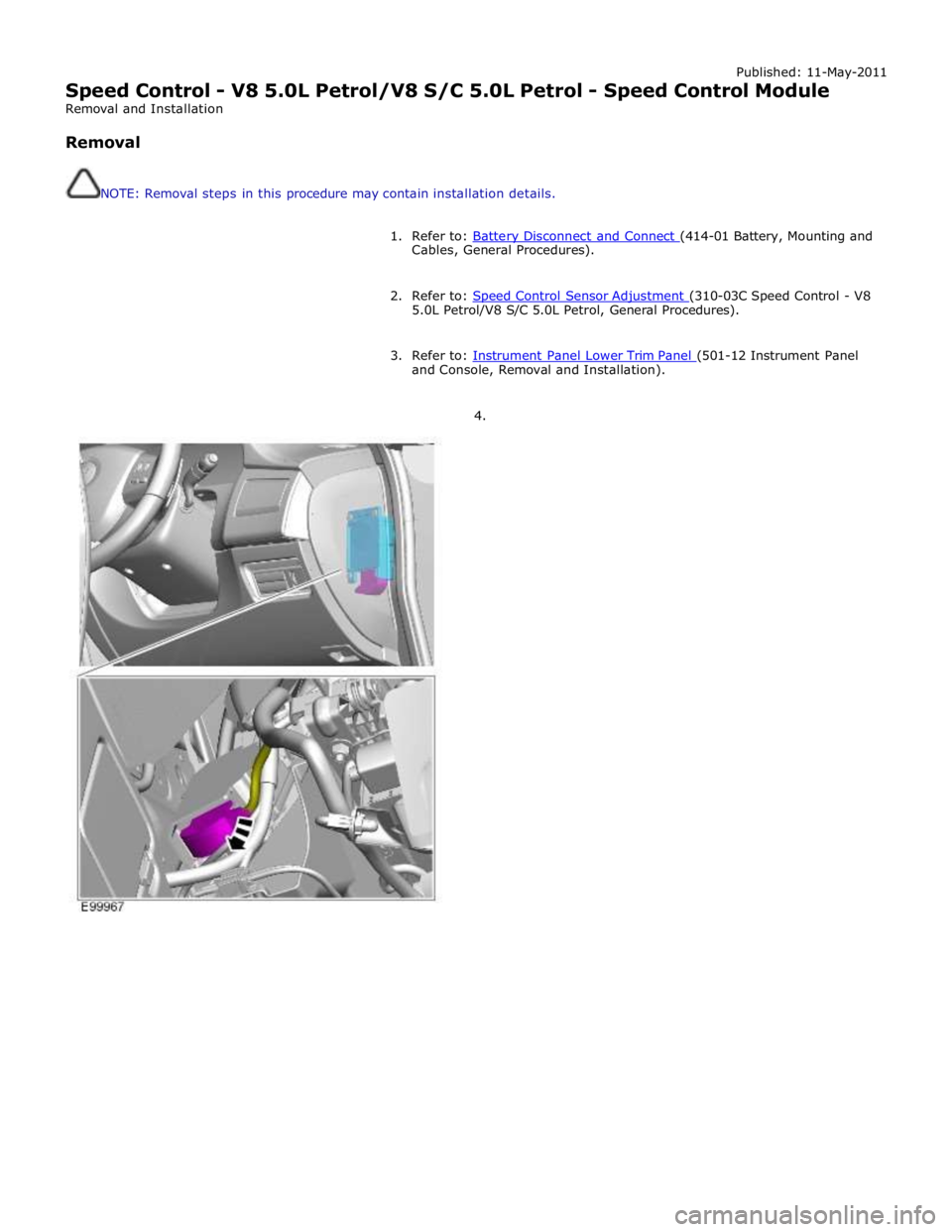
Published: 11-May-2011
Speed Control - V8 5.0L Petrol/V8 S/C 5.0L Petrol - Speed Control Module
Removal and Installation
Removal
NOTE: Removal steps in this procedure may contain installation details.
1. Refer to: Battery Disconnect and Connect (414-01 Battery, Mounting and Cables, General Procedures).
2. Refer to: Speed Control Sensor Adjustment (310-03C Speed Control - V8 5.0L Petrol/V8 S/C 5.0L Petrol, General Procedures).
3. Refer to: Instrument Panel Lower Trim Panel (501-12 Instrument Panel and Console, Removal and Installation).
4.
Page 1658 of 3039
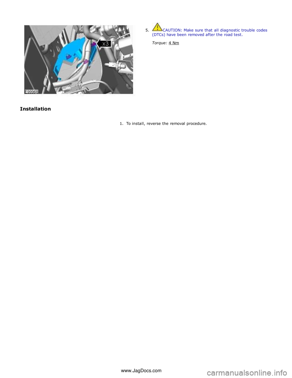
1. To install, reverse the removal procedure. www.JagDocs.com
Page 1659 of 3039
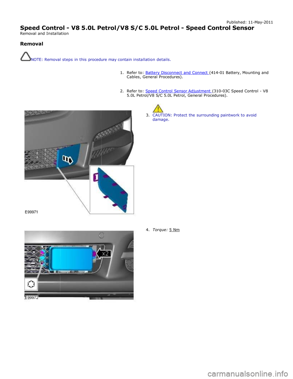
Published: 11-May-2011
Speed Control - V8 5.0L Petrol/V8 S/C 5.0L Petrol - Speed Control Sensor
Removal and Installation
Removal
NOTE: Removal steps in this procedure may contain installation details.
1. Refer to: Battery Disconnect and Connect (414-01 Battery, Mounting and Cables, General Procedures).
2. Refer to: Speed Control Sensor Adjustment (310-03C Speed Control - V8 5.0L Petrol/V8 S/C 5.0L Petrol, General Procedures).
3. CAUTION: Protect the surrounding paintwork to avoid
damage.
4. Torque: 5 Nm
Page 1660 of 3039
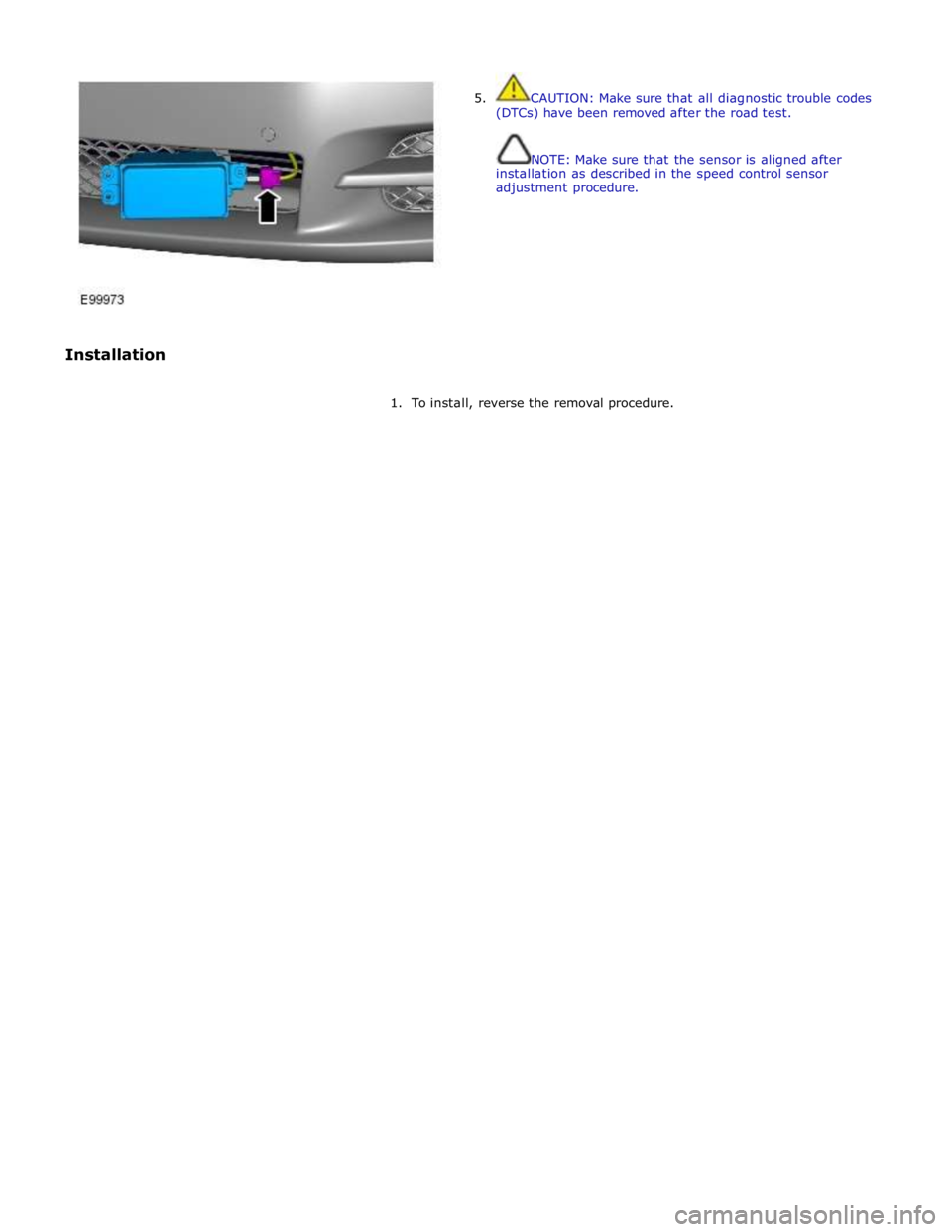
Installation 5. CAUTION: Make sure that all diagnostic trouble codes
(DTCs) have been removed after the road test.
NOTE: Make sure that the sensor is aligned after
installation as described in the speed control sensor
adjustment procedure.
1. To install, reverse the removal procedure.